Download Links
 Download Catalog Download Catalog |
Download Manual |
| Download Hardware Manual |
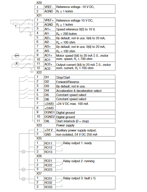
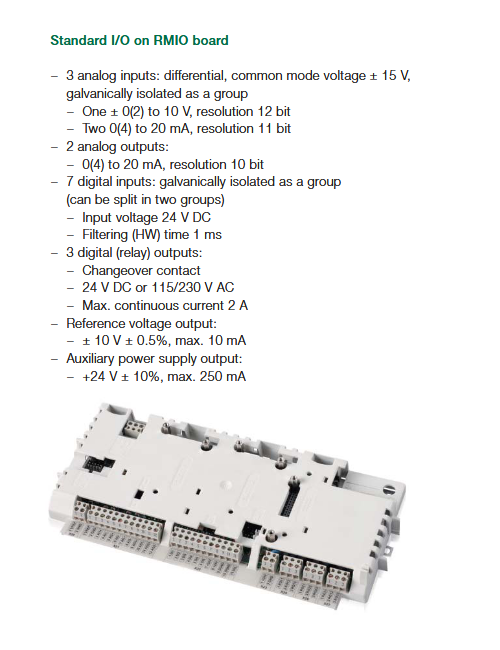
Wiring Details
Below image show terminal details:
Faults & Alarms
Search from below list for ACS800 drive faults & alarms:
| Fault Code | Cause & Solution |
|---|---|
| 4210 ACS800 TEMP | Cause: Drive IGBT temperature is excessive. Fault trip limit is 100%. Solution: 1. Check ambient conditions. 2. Check air flow and fan operation. 3. Check heatsink fins for dust pick-up. 4. Check motor power against unit power. |
| 8110 AI < MIN FUNCTION | Cause : Analogue control signal is below minimum allowed value due to incorrect signal level or failure in control wiring. Solution: 1. Check for proper analogue control signal levels. 2. Check control wiring. 3. Check Fault Function parameters. |
| AD [message] | Cause: Message generated by an EVENT block in the Adaptive Program. Solution: 1. Consult the documentation or author of the Adaptive Program. |
| FFA3 BACKUP USED | Cause: PC stored backup of drive parameters is downloaded into use. Solution: 1. Wait until download is completed. |
| 5581 BATT FAILURE | Cause: APBU branching unit memory backup battery error caused by – incorrect APBU switch S3 setting – too low battery voltage. Solution: 1. With parallel connected inverters, enable backup battery by setting actuator 6 of switch S3 to ON. 2. Replace backup battery. |
| 7114 BC OVERHEAT | Cause : Brake chopper overload. Solution: 1. Stop drive. 2. Let chopper cool down. 3. Check parameter settings of resistor overload protection function (see parameter group 27 BRAKE CHOPPER). 4. Check that braking cycle meets allowed limits. 5. Check that drive supply AC voltage is not excessive. |
| FF74 BRAKE ACKN | Cause : Unexpected state of brake acknowledge signal. Solution: 1. See parameter group 42 BRAKE CONTROL. 2. Check connection of brake acknowledgement signal |
| 7112 BR OVERHEAT | Cause : Brake resistor overload. Solution: 1. Stop drive. 2. Let resistor cool down. 3. Check parameter settings of resistor overload protection function (see parameter group 27 BRAKE CHOPPER). 4. Check that braking cycle meets allowed limits. |
| FF37 CALIBRATION DONE | Cause: Calibration of output current transformers is completed. Solution: 1. Continue normal operation. |
| FF36 CALIBRATION REQUIRED | Cause: Calibration of output current transformers is required. Displayed at start if drive is in scalar control (parameter 99.04) and scalar fly start feature is on (parameter 21.08). Solution: Calibration starts automatically. Wait for a while. |
| 7510 COMMUNICATION MODULE | Cause : Cyclical communication between drive and master is lost. Solution: 1. Check status of fieldbus communication. 2. Check parameter settings: – group 51 COMM MODULE DATA(for fieldbus adapter) – group 52 STANDARD MODBUS (for Standard Modbus Link). 3. Check Fault Function parameters. 4. Check cable connections. 5. Check if master can communicate 6. This is a programmable Fault Function, check parameter 30.18, 30.19 |
| 3211 DC BUS LIMIT | Cause : Drive limits torque due to too high or too low intermediate circuit DC voltage. Solution: 1. Informative alarm 2. Check Fault Function parameters. |
| 2330 EARTH FAULT | Cause : Drive has detected load unbalance typically due to earth fault in motor or motor cable. Solution: 1. Check there are no power factor correction capacitors or surge absorbers in motor cable. 2. Check that there is no earth fault in motor or motor cables: – measure insulation resistances of motor and motor cable. |
| 7310 ENCODER CABLE | Cause : Pulse encoder phase signal is missing. Solution: 1. Check pulse encoder and its wiring. 2. Check pulse encoder interface module and its wiring. 3. This is a programmable Fault Function check parameter 50.07. |
| 7302 ENCODER A<>B | Cause: Pulse encoder phasing is wrong: Phase A is connected to terminal of phase B and vice versa. Solution: Interchange connection of pulse encoder phases A and B. |
| 7301 ENCODER ERROR | Cause : Communication fault between pulse encoder and pulse encoder interface module and between module and drive. Solution: 1. Check pulse encoder and its wiring, pulse encoder interface module and its wiring, parameter group 50 ENCODER MODULE settings. |
| FF83 FAN OTEMP | Cause : Excessive temperature of drive output filter fan. Supervision is in use in step-up drives. Solution: 1. Stop drive. Let it cool down. 2. Check ambient temperature. 3. Check fan rotates in correct direction and air flows freely. |
| FF38 HW RECONF RQ | Cause: Inverter type (e.g. sr0025_3) has been changed. Inverter type is usually changed at factory or during drive implementation. Solution: Wait until alarm POWEROFF! activates and switch control board power off to validate inverter type change. |
| FF32 ID DONE | Cause : Drive has performed motor identification magnetisation and is ready for operation. This warning belongs to normal start-up procedure. Solution: Continue drive operation. |
| FF31 ID MAGN | Cause : Motor identification magnetisation is on. This warning belongs to normal start-up procedure. Solution: Wait until drive indicates that motor identification is completed. |
| FF30 ID MAGN REQ | Cause : Motor identification is required. This warning belongs to normal start-up procedure. Drive expects user to select how motor identification should be performed: By Identification Magnetisation or by ID Run. Solution: Start Identification Magnetisation by pressing Start key, or select ID Run and start (see parameter 99.10). |
| FF68 ID N CHANGED | Cause: Drive ID number has been changed from 1. Solution: Change ID number back to 1. |
| FF35 ID RUN | Cause : Motor identification Run is on. Solution: 1. Wait until drive indicates that motor identification Run is completed. |
| FF33 ID RUN SEL | Cause : Motor Identification Run is selected, and drive is ready to start ID Run. This warning belongs to ID Run procedure. Solution: 1. Press Start key to start Identification Run. |
| FF81 IN CHOKE TEMP | Cause: Excessive input choke temperature Stop drive. Solution: 1. Let it cool down. 2. Check ambient temperature. 3. Check that fan rotates in correct direction and air flows freely. |
| 2212 INV CUR LIMIT | Cause : Internal inverter current or power limit has been exceeded. Solution: 1. Reduce load or increase ramp time. 2. Limit inverter actual power or decrease line- side converter reactive power generation reference value (parameter 95.06 LCU Q PW REF). 3. Check Fault Function parameters. |
3200 INV DISABLED | Cause: Optional DC switch has opened while unit was stopped. Solution: 1. Close DC switch. 2. Check AFSC-0x Fuse Switch Controller unit. |
| 4290 INV OVERTEMP | Cause : Converter module temperature is excessive. Solution: 1. Check ambient temperature. If it exceeds 40°C, ensure that load current does not exceed derated load capacity of drive. 2. Check that ambient temperature setting is correct (parameter 95.10). 3. Check converter module cooling air flow and fan operation. 4. Cabinet installation: Check cabinet air inlet filters. Change when necessary. 5. Modules installed in cabinet by user: Check that cooling air circulation in cabinet has been prevented with air baffles. 6. Check inside of cabinet and heatsink of converter module for dust pick-up. Clean when necessary. |
| FF8B IO CONFIG | Cause : Input or output of optional I/O extension or fieldbus module has been selected as signal interface in application program but communication to appropriate I/O extension module has not been set accordingly Solution: 1. Check Fault Function parameters. 2. Check parameter group 98 OPTION MODULES. |
| FF69 MACRO CHANGE | Cause: Macro is restoring or User macro is being saved. Solution: 1. Wait until drive has finished task. |
| FF88 MOD BOARD T | Cause: Overtemperature in AINT board of inverter module. Solution: 1. Check inverter fan. 2. Check ambient temperature. |
| FF89 MOD CHOKE T | Cause: Overtemperature in choke of liquid cooled R8i inverter module. Solution: 1. Check inverter fan. 2. Check ambient temperature. 3. Check liquid cooling system. |
| 2300 MOTOR CURRENT LIMIT | Cause : Drive limits motor current according to current limit defined by parameter 20.03 MAXIMUM CURRENT. Solution: 1. Reduce load or increase ramp time. 2. Increase parameter 20.03 MAXIMUM CURRENT value. 3. Check Fault Function parameters. 4. This is a programmable Fault Function check parameter 30.23. |
| 7121 MOTOR STALL | Cause : Motor is operating in stall region due to e.g. excessive load or insufficient motor power. Solution: 1. Check motor load and drive ratings. 2. Check Fault Function parameters. 3. This is a programmable Fault Function check parameter 30.10. |
| FF34 MOTOR STARTS | Cause : Motor Identification Run starts. This warning belongs to ID Run procedure. Solution: Wait until drive indicates that motor identification is completed. |
| 4310 MOTOR TEMP | Cause : Motor temperature is too high (or appears to be too high) due to excessive load, insufficient motor power, inadequate cooling or incorrect start-up data. Solution: 1. Check motor ratings, load and cooling. 2. Check start-up data. 3. Check Fault Function parameters. |
| 4312 MOTOR 1 TEMPERATURE | Cause: Measured motor temperature has exceeded alarm limit set by parameter 35.02. Solution: 1. Check value of alarm limit. 2. Check that actual number of sensors corresponds to value set by parameter. 3. Let motor cool down. 4. Ensure proper motor cooling: Check cooling fan, clean cooling surfaces, etc. |
| 4313 MOTOR 2 TEMPERATURE | Cause: Measured motor temperature has exceeded alarm limit set by parameter 35.05. Solution: 1. Check value of alarm limit. 2. Check that actual number of sensors corresponds to value set by parameter. 3. Let motor cool down. 4. Ensure proper motor cooling: Check cooling fan, clean cooling surfaces, etc. |
| FF86 MOTOR POWER LIMIT | Cause: Drive limits motor power according to limits defined by parameters 20.11 and 20.12. Solution: 1. This is a informative alarm 2. Check parameter 20.11 P MOTORING LIM and 20.12 P GENERATING LIM settings. 3. Check Fault Function parameters. |
| FF85 MOTOR TORQUE LIMIT | Cause: Drive limits motor torque according to calculated motor pull-out torque limit and minimum and maximum torque limits defined by parameters 20.13 and 20.14. Solution: 1. Informative alarm 2. Check parameter 20.13 MIN TORQ SEL and 20.14 MAX TORQ SEL settings. 3. Check Fault Function parameters. If LIMIT WORD 1 bit 0 TORQ MOTOR LIM is 1, – check motor parameter settings (parameter group 99 START-UP DATA) – ensure that ID run has been completed successfully. |
| 5300 PANEL LOSS | Cause : Control panel selected as active control location for drive has ceased communicating. Solution: 1. Check panel connection. 2. Check control panel connector. 3. Replace control panel in mounting platform. 4. Check Fault Function parameters. |
| FFD0 POINTER ERROR | Cause: Source selection (pointer) parameter points to non existing parameter index. Solution: 1. Check source selection (pointer) parameter settings. |
| FF39 ->POWEROFF! | Cause: Inverter type (e.g. sr0025_3) has been changed. Inverter type is usually changed at factory or during drive implementation. Solution: Switch control board power off to validate inverter type change. |
| 5210 PPCC LINK | Cause : Fiber optic link to INT board is faulty. Solution: 1. Check fibre optic cables or galvanic link. With frame sizes R2-R6 link is galvanic. 2. If RMIO is powered from external supply, ensure that supply is on. 3. See parameter 16.09 – CTRL BOARD SUPPLY. |
| 5482 PP OVERLOAD | Cause : Excessive IGBT junction to case temperature. This can be caused by excessive load at low frequencies (e.g. fast direction change with excessive load and inertia). Solution: 1. Increase ramp time. 2. Reduce load. |
| 4280 REPLACE FAN | Cause : Running time of inverter cooling fan has exceeded its estimated life time Solution: 1. Replace fan. 2. Reset fan run time counter 01.44. |
| FF8E RUN ENABLE | Cause : No Run enable signal received. Solution: 1. Check setting of parameter 16.01. 2. Switch on signal or check wiring of selected source. |
| FF8C SLEEP MODE | Cause: Sleep function has entered sleeping mode. Solution: See parameter group 40 PID CONTROL. |
| FF7A START INHIBI | Cause : Safe torque off function has been activated while drive was stopped. Or: Optional start inhibit hardware logic is activated. Solution: 1. Close Safe torque off function switch. If switch is closed and warning is still active, check power supply at ASTO board input terminals. Replace ASTO board. 2. Check start inhibit circuit (AGPS board). |
| FF8D START INTERLOCK | Cause : No Start Interlock signal received. Solution: 1. Check circuit connected to Start Interlock input on RMIO board. |
| FF87 SYNCRO SPEED | Cause: Value of motor nominal speed set to parameter 99.08 is not correct: Value is too near synchronous speed of motor. Tolerance is 0.1%. This warning is active only in DTC mode. Solution: Check nominal speed from motor rating plate and set parameter 99.08 exactly accordingly. |
| 4380 TEMP DIF xx y | Cause: 1. Excessive temperature difference between several parallel connected inverter modules. xx (1…12) refers to inverter module number and y refers to phase (U, V, W). 2. Alarm is indicated when temperature difference is 15°C. Fault is indicated when temperature difference is 20°C. 3. Excessive temperature can be caused e.g. by unequal current sharing between parallel connected inverters. Solution: 1. Check cooling fan. 2. Replace fan. 3. Check air filters. |
| 4311 THERMISTOR | Cause: Motor temperature is excessive. Motor thermal protection mode selection is TEMP SENSOR. Solution: 1. Check motor ratings and load. 2. Check start-up data. 3. Check thermistor connections to digital input DI6. 4. This is a programmable Fault Function check parameter 30.04…30.05. |
| FF91 T MEAS ALM | Cause: Motor temperature measurement is out of acceptable range. Solution: 1. Check connections of motor temperature measurement circuit. |
| FF6A UNDERLOAD | Cause : Motor load is too low due to e.g. release mechanism in driven equipment. Solution: 1. Check for problem in driven equipment. 2. Check Fault Function parameters. |
| 2312 USER L CURVE | Cause: Integrated motor current has exceeded load curve defined by parameters in group 72 USER LOAD CURVE. Solution: 1. Check parameter group 72 USER LOAD CURVE settings. 2. Reduce load. |
| DOWNLOADING FAILED | Cause: Download function of panel has failed. No data has been copied from panel to drive. Solution: 1. Make sure panel is in local mode. 2. Retry (there might be interference on link). |
| DRIVE IS RUNNING DOWNLOADING NOT POSSIBLE | Cause: Downloading is not possible while motor is running. Solution: Stop motor. Perform downloading. |
| NO COMMUNICATION | Cause: Cabling problem or hardware malfunction on Panel Link Solution: 1. Check Panel Link connections. 2. Press RESET key. Panel reset may take up to half a minute, please wait. |
| NO FREE ID NUMBERS ID NUMBER SETTING NOT POSSIBLE | Cause: Panel Link already includes 31 stations. Solution: Disconnect another station from link to free ID number. |
| NOT UPLOADED DOWNLOADING NOT POSSIBLE | Cause: No upload function has been performed. Solution: Perform upload function before downloading. |
| UPLOADING FAILED | Cause: Upload function of panel has failed. No data has been copied from drive to panel. Solution: Retry (there might be interference on link). |
| WRITE ACCESS DENIED PARAMETER SETTING NOT POSSIBLE | Cause: Certain parameters do not allow changes while motor is running. If tried, no change is accepted, and warning is displayed. Parameter lock is on. Solution: 1. Stop motor, then change parameter value. 2. Open parameter lock (see parameter 16.02). |
| 4210 ACS800 TEMP | Cause : Drive IGBT temperature is excessive. Fault trip limit is 100%. Solution: 1. Check ambient conditions. 2. Check air flow and fan operation. 3. Check heatsink fins for dust pick-up. 4. Check motor power against unit power. |
| 8110 AI < MIN FUNCTION | Cause: Analogue control signal is below minimum allowed value due to incorrect signal level or failure in control wiring. Solution: 1. Check for proper analogue control signal levels. 2. Check control wiring. 3. Check Fault Function parameters. |
| FFA2 BACKUP ERROR | Cause: Failure when restoring PC stored backup of drive parameters. Solution: 1. Retry. 2. Check connections. 3. Check that parameters are compatible with drive. |
| 7114 BC OVERHEAT | Cause : Brake chopper overload. Solution: 1. Let chopper cool down. 2. Check parameter settings of resistor overload protection function (see parameter group 27 BRAKE CHOPPER). 3. Check that braking cycle meets allowed limits. 4. Check that drive supply AC voltage is not excessive. |
| 7113 BC SHORT CIRCUIT | Cause : Short circuit in brake chopper IGBT(s). Solution: 1. Replace brake chopper. 2. Ensure brake resistor is connected and not damaged. |
| FF74 BRAKE acknowledge | Cause : Unexpected state of brake acknowledge signal. Solution: 1. See parameter group 42 BRAKE CONTROL. 2. Check connection of brake acknowledgement signal. |
| 7110 BR BROKEN | Cause : Brake resistor is not connected or it is damaged. Resistance rating of brake resistor is too high. Solution: 1. Check resistor and resistor connection. 2. Check that resistance rating meets specifications. |
| 7112 BR OVERHEAT | Cause : Brake resistor overload. Solution: 1. Let resistor cool down. 2. Check parameter settings of resistor overload protection function (see parameter group 27 BRAKE CHOPPER). 3. Check that braking cycle meets allowed limits. 4. Check that drive supply AC voltage is not excessive. |
| 7111 BR WIRING | Cause : Wrong connection of brake resistor. Solution: 1. Check resistor connection. 2. Ensure brake resistor is not damaged. |
| FF82 CHOKE OTEMP | Cause: Excessive temperature of drive output filter. Supervision is in use in step-up drives. Solution: 1. Let drive cool down. 2. Check ambient temperature. 3. Check filter fan rotates in correct direction and air flows freely. |
| 7510 COMMUNICATION MODULE | Cause : Cyclical communication between drive and master is lost. Solution: 1. Check status of fieldbus communication. 2. Check parameter settings: – group 51 COMM MODULE DATA(for fieldbus adapter), or – group 52 STANDARD MODBUS (for Standard Modbus Link). 3. Check Fault Function parameters. 4. Check cable connections. 5. Check if master can communicate. |
| 4110 CTRL B TEMP | Cause : Control board temperature is above 88°C. Solution: 1. Check ambient conditions. 2. Check air flow. 3. Check main and additional cooling fans. |
| 2211 CURRENT measurement | Cause : Current transformer failure in output current measurement circuit. Solution: 1. Check current transformer connections to Main Circuit Interface Board, INT |
FF80 DC HIGH RUSH | Cause: Drive supply voltage is excessive. When supply voltage is over 124% of unit voltage rating (415, 500 or 690 V), motor speed rushes to trip level (40% of nominal speed). Solution: 1. Check supply voltage level, drive rated voltage and allowed voltage range of drive. |
| 3210 DC OVERVOLT | Cause : Excessive intermediate circuit DC voltage. DC overvoltage trip limit is 1.3 × 1.35 × U1max, where U1max is maximum value of supply voltage range. For 400 V units, U1max is 415 V. For 500 V units, U1max is 500 V. For 690 V units, U1max is 690 V. Actual voltage in intermediate circuit corresponding to the supply voltage trip level is 728 V DC for 400 V units, 877 V DC for 500 V units, and 1210 V DC for 690 V units. Solution: 1. Check that overvoltage controller is on (parameter 20.05). 2. Check supply voltage for static or transient overvoltage. 3. Check brake chopper and resistor (if used). 4. Check deceleration time. 5. Use coast-to-stop function (if applicable). 6. Retrofit frequency converter with brake chopper and brake resistor. |
| 3220 DC UNDERVOLT | Cause : Intermediate circuit DC voltage is not sufficient due to missing supply voltage phase, blown fuse or rectifier bridge internal fault. Solution: 1. Check main supply and fuses. |
| 2330 EARTH FAULT | Cause : Drive has detected load unbalance typically due to earth fault in motor or motor cable. Solution: 1. Check there are no power factor correction capacitors or surge absorbers in motor cable. 2. Check that there is no earth fault in motor or motor cables: – measure insulation resistances of motor and motor cable. |
| 7310 ENCODER CABLE | Cause : Pulse encoder phase signal is missing. Solution: 1. Check pulse encoder and its wiring. 2. Check pulse encoder interface module and its wiring. |
| 7302 ENCODER A<>B | Cause: Pulse encoder phasing is wrong: Phase A is connected to terminal of phase B and vice versa. Solution: Interchange connection of pulse encoder phases A and B. |
| 7301 ENCODER ERROR | Cause : Communication fault between pulse encoder and pulse encoder interface module and between module and drive. Solution: 1. Check pulse encoder and its wiring, pulse encoder interface module and its wiring and parameter group 50 ENCODER MODULE settings. |
| 9000 EXTERNAL FAULT | Cause : Fault in external device. (This information is configured through one of programmable digital inputs.) Solution: 1. Check external devices for faults. 2. Check parameter 30.03 EXTERNAL FAULT |
| FF8F FORCED TRIP | Cause: Generic Drive Communication Profile trip command Solution: See appropriate communication module manual. |
| FF53 GD DISABLED | Cause: AGPS power supply of parallel connected R8i inverter module has been switched off during run. X (1…12) refers to inverter module number. Solution: 1. Check Prevention of Unexpected Start-up circuit. 2. Replace AGPS board of R8i inverter module. |
| FF84 ID RUN FAIL | Cause : Motor ID Run is not completed successfully. Solution: 1. Check maximum speed (parameter 20.02). It should be at least 80% of motor nominal speed (parameter 99.08). |
| FF81 IN CHOKE TEMP | Cause: Excessive input choke temperature Stop drive. Let it cool down. Solution: 1. Check ambient temperature. 2. Check that fan rotates in correct direction and air flows freely. |
| 5410 INT CONFIG | Cause: Number of inverter modules is not equal to original number of inverters. Solution: 1. Check status of inverters. See signal 04.01 FAULTED INT INFO. 2. Check fibre optic cables between APBU and inverter modules. 3. If Reduced Run function is used, remove faulted inverter module from main circuit and write number of remaining inverter modules into parameter 95.03 INT CONFIG USER. 4. Reset drive. |
| 3200 INV DISABLED | Cause: Optional DC switch has opened while unit was running or start command was given. Solution: 1. Close DC switch. 2. Check AFSC-0x Fuse Switch Controller unit. |
| 4290 INV OVERTEMP | Cause : Converter module temperature is excessive. Solution: 1. Check ambient temperature. 2. If it exceeds 40°C, ensure that load current does not exceed derated load capacity of drive. 3. Check that ambient temperature setting is correct (parameter 95.10). 4. Check converter module cooling air flow and fan operation. 5. Cabinet installation: Check cabinet air inlet filters. Change when necessary. 6. Modules installed in cabinet by user: Check that cooling air circulation in cabinet has been prevented with air baffles. 7. Check inside of cabinet and heatsink of converter module for dust pick-up. Clean when necessary. 8. Reset and restart after problem is solved and let converter module cool down. |
| 7000 I/O COMM ERROR | Cause : Communication error on control board, channel CH1 Electromagnetic interference. Solution: 1. Check connections of fibre optic cables on channel CH1. 2. Check all I/O modules (if present) connected to channel CH1. 3. Check for proper earthing of equipment. Check for highly emissive components nearby. |
| FF51 LINE CONV | Cause: Fault on line side converter. Solution: 1. Shift panel from motor side converter control board to line side converter control board. 2. See line side converter manual for fault description. |
| FF88 MOD BOARD T | Cause: Overtemperature in AINT board of inverter module. Solution: 1. Check inverter fan. 2. Check ambient temperature. |
| FF89 MOD CHOKE T | Cause: Overtemperature in choke of liquid cooled R8i inverter module. Solution: 1. Check inverter fan. 2. Check ambient temperature. 3. Check liquid cooling system. |
| FF56 MOTOR PHASE | Cause : One of motor phases is lost due to fault in motor, motor cable, thermal relay (if used) or internal fault. Solution: 1. Check motor and motor cable. 2. Check thermal relay (if used). 3. Check Fault Function parameters. Disable this protection. |
| 7121 MOTOR STALL | Cause: Motor is operating in stall region due to e.g. excessive load or insufficient motor power. Solution: 1. Check motor load and drive ratings. 2. Check Fault Function parameters. |
| 4310 MOTOR TEMP | Cause : Motor temperature is too high (or appears to be too high) due to excessive load, insufficient motor power, inadequate cooling or incorrect start-up data. Solution: 1. Check motor ratings and load. 2. Check start-up data. 3. Check Fault Function parameters. |
| 4312 MOTOR 1 TEMP | Cause: Measured motor temperature has exceeded fault limit set by parameter 35.03. Solution: 1. Check value of fault limit. 2. Let motor cool down. 3. Ensure proper motor cooling: Check cooling fan, clean cooling surfaces, etc. |
| 4313 MOTOR 2 TEMP | Cause: Measured motor temperature has exceeded fault limit set by parameter 35.06. Solution: 1. Check value of fault limit. 2. Let motor cool down. 3. Ensure proper motor cooling: Check cooling fan, clean cooling surfaces, etc. |
| FF52 NO MOT DATA | Cause : Motor data is not given or motor data does not match with inverter data. Solution: 1. Check motor data parameters 99.04…99.09. |
| 2310 OVER CURRENT | Cause : Output current exceeds trip limit. Solution: 1. Check motor load. 2. Check acceleration time. 3. Check motor and motor cable (including phasing). 4. Check encoder cable (including phasing). 5. Check motor nominal values from group 99 START-UP DATA to confirm that motor model is correct. 6. Check that there are nopower factor correction or surge absorbers in motor cable. |
| 7123 OVERFREQ | Cause: Motor is turning faster than highest allowed speed due to incorrectly set minimum/ maximum speed, insufficient braking torque or changes in load when using torque reference. Solution: 1. Check minimum/maximum speed settings. 2. Check adequacy of motor braking torque. 3. Check applicability of torque control. 4. Check need for brake chopper and resistor(s). |
| FF55 OVER SWFREQ | Cause: Switching frequency is too high. Check motor parameter settings (parameter group 99 START-UP DATA) Solution: Ensure that ID run has been completed successfully. |
| 5300 PANEL LOSS | Cause : Control panel or Drive Window selected as active control location for drive has ceased communicating. Solution: 1. Check panel connection. 2. Check control panel connector. 3. Replace control panel in mounting platform. 4. Check Fault Function parameters. 5. Check Drive Window connection. |
| 6320 PARAM CRC | Cause: CRC (Cyclic Redundancy Check) error. Solution: 1. Switch control board power off and on again. 2. Reload firmware to control board. 3. Replace control board. |
| 3381 POWERFAIL | Cause: INT board powerfail in several inverter units of parallel connected inverter modules. Solution: 1. Check that INT board power cable is connected. 2. Check that POW board is working correctly. 3. Replace INT board. |
| 5210 PPCC LINK | Cause : Fiber optic link to INT board is faulty. Solution: 1. Check fibre optic cables or galvanic link. With frame sizes R2-R6 link is galvanic. 2. If RMIO is powered from external supply, ensure that supply is on. 3. See parameter 16.09 CTRL BOARD SUPPLY. |
| 5482 PP OVERLOAD | Cause: Excessive IGBT junction to case temperature. This fault protects IGBT(s) and it can be activated by short circuit at output of long motor cables. Solution: 1. Check motor cables. |
| 2340 SHORT CIRCUIT | Cause: Short-circuit in motor cable(s) or motor. Solution: 1. Check motor and motor cable. 2. Check there are no power factor correction capacitors or surge absorbers in motor cable. |
| FF8A SLOT OVERLAP | Cause: Two option modules have same connection interface selection. Solution: 1. Check connection interface selections in group 98 OPTION MODULES. |
| FF7A START INHIBIT | Cause : Safe torque off has been activated during motor run or motor start command has been given when Safe torque off is active. Or: Optional start inhibit hardware logic is activated. Solution: 1. Close Safe torque off switch. If switch is closed and fault is still active, check power supply at ASTO board input terminals. Replace ASTO board. 2. Check start inhibit circuit (AGPS board). |
| 3130 SUPPLY PHASE | Cause : Intermediate circuit DC voltage is oscillating due to missing supply voltage phase, blown fuse or rectifier bridge internal fault. Trip occurs when DC voltage ripple is 13% of DC voltage. Solution: 1. Check main supply fuses. 2. Check for main supply imbalance. |
| 4380 TEMP DIF xx y | Cause: Excessive temperature difference between several parallel connected inverter modules. xx (1…12) refers to inverter module number and y refers to phase (U, V, W). Alarm is indicated when temperature difference is 15°C. Fault is indicated when temperature difference is 20°C Excessive temperature can be caused e.g. by unequal current sharing between parallel connected inverters. Solution: 1. Check cooling fan. 2. Replace fan. 3. Check air filters. |
| FF50 THERMAL MODE | Cause: Motor thermal protection mode is set to DTC for high-power motor. Solution: See parameter 30.05. |
| 4311 THERMISTOR | Cause: Motor temperature is excessive. Motor thermal protection mode selection is TEMP SENSOR. Solution: 1. Check motor ratings and load. 2. Check start-up data. 3. Check thermistor connections to digital input DI6. 4. This is a programmable Fault Function, check parameter 30.04…30.05 |
| FF6A UNDERLOAD | Cause :Motor load is too low due to e.g. release mechanism in driven equipment. Solution: 1. Check for problem in driven equipment. 2. Check Fault Function parameters. |
| 2312 USER L CURVE | Cause: Integrated motor current has exceeded load curve defined by parameter group 72 USER LOAD CURVE. Solution: 1. Check parameter group 72 USER LOAD CURVE settings. 2. After motor cooling time specified by parameter 72.20 LOAD COOLING TIME has elapsed, fault can be reset. |
| FFA1 USER MACRO | Cause: No User Macro saved or file is defective. Solution: Create User Macro. |
| FF54 Run Disabled | Cause: No Run enable signal received. Solution: 1. Check the setting of parameter 16.01. Switch on the signal or check the wiring of the selected source. |
| F010 ANTI JAM ON | Cause: Anti jam function is active. Solution: Wait until the function has finished. |
| F01A AUTOCHANGE | Cause: Autochange function is being performed. Solution: Refer to the description of parameters 42.06 and 42.07. |
| FFFC BRK LONG TIME | Cause: Brake acknowledge active after brake close delay has elapsed. Drive active with zero speed reference. Solution: 1. See parameter group 42 BRAKE CONTROL. 2. Check connection of brake acknowledgement signal. 3. Check mechanical brake. |
| CTRL LOC DIFF | Cause: Master and Follower are not in the same control location. Solution: 1. Check that the Master and the Follower are both in EXT2. |
| FFF8 FAST STOP | Cause: Fast Stop Signal 10.10 activated. Solution: Deactivate the Fast Stop signal. |
| FFFD FLWR1 LIM/FLT | Cause: Follower 1 has gone into a fault or has hit any of the limits. This message is displayed in the Master drive only Solution: See Follower 1 drive for more detailed description of fault of limit. |
| FFFE FLWR2 LIM/FLT | Cause: Follower 2 has gone into a fault or has hit any of the limits. This message is displayed in the Master drive only Solution: 1. See Follower 2 drive for more detailed description of fault of limit. |
| FFB5 FLWR3 LIM/FLT | Cause: Follower 3 has gone into a fault or has hit any of the limits. This message is displayed in the Master drive only Solution: 1. See Follower 3 drive for more detailed description of fault of limit. |
| FFB4 FLWR4 LIM/FLT | Cause: Follower 4 has gone into a fault or has hit any of the limits. This message is displayed in the Master drive only Solution: 1. See Follower 4 drive for more detailed description of fault of limit. |
| FFF6 HIGHEND LIMIT | Cause: High-end limit Signal 10.12 activated in the Up direction Solution: 1. Run the motor in the opposite direction and deactivate the High-end limit signal. |
| FFB1 HOMING ACTIVE | Cause: Homing activation signal 10.21 activated in EXT 1 control Solution: Homing sequence is activated. Start the drive and complete the homing sequence. After homing sequence is done deactivate the homing active signal. |
| FFB0 HOMING DONE | Cause: Homing sequence is completed in EXT 1 control. The position is initialized to the value define in par 78.10. Solution: Homing sequence is completed. Deactivate the homing active signal and continue operation. |
| FFF7 LOWEND LIMIT | Cause: Low-end limit Signal 10.13 activated in the down direction Solution: Run the motor in the opposite direction and deactivate the Low-end limit signal. |
| FFFA OYSTICK CHECK | Cause: Hardware error in the configured joystick. Solution: Check joystick connection. |
| FFB8 LOAD SP UP LIMIT | Cause: The speed reference is limited in the forward direction according to the Load speed control function. Solution: 1. Check motor current settings and group 77 settings. |
| FFB9 LOAD SP DW LIMIT | Cause: The speed reference is limited in the reverse direction according to the Load speed control function. Solution: 1. Check motor current settings and group 77 settings. |
| FFB2 MASTERLIM/FLT | Cause: Master drive has gone into a fault or has hit any of the limits. This message is displayed in the Follower drives only Solution: 1. See Master drive for more detailed description of fault of limit. |
| FFF4 SLOW DOWN UP | Cause: Slowdown signal 10.09 activated in the Up direction. Solution: Run the motor in the opposite direction and deactivate the Slowdown signal. Or let the drive run in the limited speed reference. |
| FFF5 SLOW DOWN DOWN | Cause: Slowdown signal 10.09 activated in the down direction. Solution: Run the motor in the opposite direction and deactivate the Slowdown signal. Or let the drive run in the limited speed reference. |
| FFB3 START HIGH | Cause: The Start command is active when the drive is powered ON. The Start command remains ON after a fault or fast stop has occurred and a reset is done. Solution: Start command should be made OFF and then can be made ON for a start sequence. |
| FFFB ZERO POS WARNING | Cause: Start command with incorrect Zero position input. Solution: 1. Check for Zero position DI. |
| FFF3 BRAKE SLIP FLT | Cause: The brake slipped and the motor speed exceeded the motor slip speed 42.11 for a period of slip fault delay 42.12 time. Solution: 1. Check brakes. |
| FFBA FLWR1 COM FLT | Cause: Follower 1 Communication error. Solution: 1. Check CH2 communication, communication settings. |
| FFBB FLWR2 COM FLT | Cause: Follower 2 Communication error. Solution: 1. Check CH2 communication, communication settings. |
| FFBc FLWR3 COM FLT | Cause: Follower 3 Communication error. Solution: 1. Check CH2 communication, communication settings. |
| FFBd FLWR4 COM FLT | Cause: Follower 4 Communication error. Solution: 1. Check CH2 communication, communication settings. |
| FFBF INV LIMIT | Cause: The fault is generated when the drive has hit TORQUE INVERTER CURRENT LIMIT or IPP OVERTEMP ALM is active and a period of 200 ms has elapsed. The fault condition is only checked when the generating power is more than 10% of motor nominal power and the speed is greater than 5% of the maximum speed. Solution: 1. Check the Speed controller torque settings. 2. Check torque, speed, power limit settings. |
| FFF0 MOTOROVER SPD | Cause: The speed exceeds the MOT OVERSPEED LEV (Par. 74.01). Solution: 1. Check Torque and Current limit settings 2. Check motor and motor cables 3. Check pulse encoder connections if used. |
| FF7D SAFETYCLS FLT | Cause: When an encoder is not used and the actual speed is below 1% of the max speed for more than 2 seconds with the Start command active, the drive trips on SAFETYCLS FLT. Solution: 1. Check references. 2. Check motor model settings. |
| FFF1 SPD MATCH FLT | Cause: If speed error at set point is higher than SP DEV LEV (Par. 75.02) or the actual speed change per second during acceleration/ deceleration is less than SPD CHG PER SEC (Par. 75.04) for a time longer than SPD MATCH FLT TD (Par. 75.03) the drive will trip for SPD MATCH FLT. Solution: 1. Check ramp times. 2. Check Torque and Current limit settings. |
| FFBE SYNC FAULT | Cause: Synchronisation error of Follower drive. The error in position of the Follower drive is greater than the allowed limits. Solution: 1. Check the Synchro error limits. 2. Check encoder connections. |
| FFF2 TORQ PROVE FLT | Cause: If Torque proving is not successful, that means torque does not reach the test level within the time TORQ PROV FLT TD (Par. 76.02), the drive will trip. (Normally only used if active load, for example, hoist drive, with pulse encoder feedback. Solution: 1. Check motor and motor cables. 2. Check if setting of parameter 21.2 Control Magnetising time is to low. |
| F012 F TO MS CM LOSS | Cause: In a Multipump configuration, the master does not receive messages from a follower. Solution: 1. Check the fibre optic cabling between the drives on the Multipump link. If the drives are connected in a ring, check that all drives are powered. |
F014 HIGH LEVEL DI | Cause: Level in a tank has reached the high level connected to Digital Input. Solution: If the level is not high in the tank, check the sensor or cable condition from sensor to DI. |
| F01B INLET LOW & F01D INLET VERY LOW | Cause: Pressure at pump/fan inlet too low. Check for a closed valve on the inlet side of the pump/fan. Solution: 1. Check piping for leaks. 2. Check parameters 44.01…44.06. |
| F015 LOW LEVEL DI | Cause: Level in a tank has reached the low level connected to Digital Input. Solution: 1. If the level is not low in the tank, check the sensor or cable condition from sensor to DI. |
| F011 MS INV LOSS | Cause: The drive cannot detect a master on a Multipump link, and is not itself allowed to become master. Solution: 1. Check fibre optic cabling between the drives on the Multipump link. 2. Check that a sufficient number of drives are allowed to become master on the link. 3. Check parameter 60.17. |
| F01C OUTLET HIGH & F01E OUTLET VERY HIGH | Cause: Pressure at pump/fan outlet too high. Solution: 1. Check piping for blocks. 2. Check parameters 44.08…44.14 |
| F019 SLEEP BOOST | Cause: Sleep boost is active. Solution: This is a informative alarm. |
| F012 F TO MS CM LOSS | Cause: In a Multipump configuration, the master does not receive messages from a follower. Solution: 1. Check the fibre optic cabling between the drives on the Multipump link. If the drives are connected in a ring, check that all drives are powered. |
| F01B INLET LOW & F01D INLET VERY LOW | Cause: Pressure at pump/fan inlet too low. Solution: 1. Check for a closed valve on the inlet side of the pump/fan. 2. Check piping for leaks. 3. Check parameters 44.01…44.06 |
| F011 MS INV LOSS | Cause: Drive cannot detect a master on a Multipump link, and is not itself allowed to become master. Solution: 1. Check the fibre optic cabling between the drives on the Multipump link. If the drives are connected in a ring, check that all drives are powered. 2. Check that a sufficient number of drives are allowed to become master on the link. 3. Check parameter 60.17 |
| F01C OUTLET HIGH & F01E OUTLET VERY HIGH | Cause: Pressure at the pump/fan outlet too high. Solution: 1. Check piping for blocks. 2. Check parameters 44.08… 44.14. |
| F013 SHARE IO COM | Cause: Analogue input data sharing is enabled but no data can be received. Solution: 1. Check the fibre optic cabling between the drives. 2. Check the analogue input signal wiring. |
| F016 START SEL WRG | Cause: Pulse-type start/stop command is selected for external control location 2 (EXT2) when either the Multipump or Level control macro is active. Solution: 1. Select a non-pulse start/stop source at parameter 10.02 EXT 2 STRT/STP/DI. |