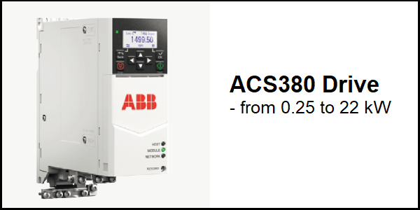
Download Links
 Download Catalog Download Catalog |
Download Manual |
| Download Hardware Manual |
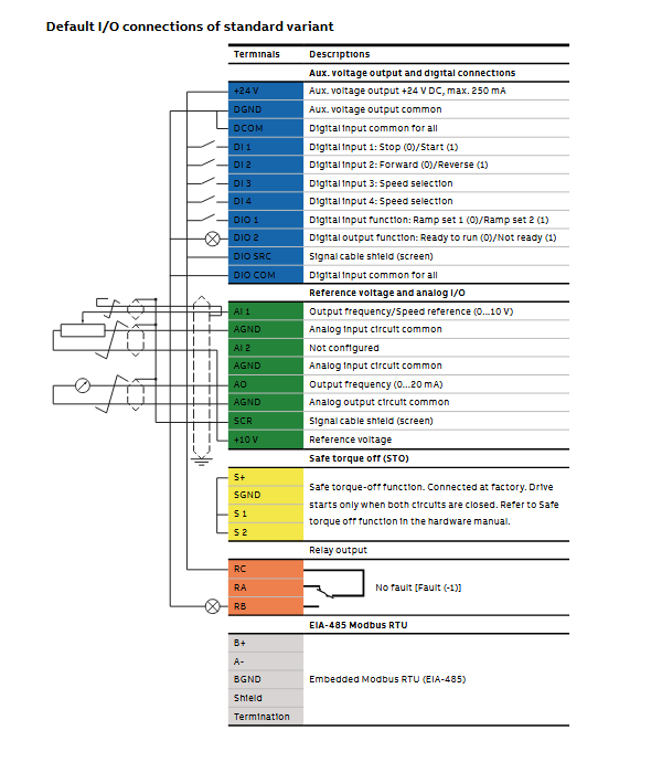
Wiring Details
Below image show terminal details:
Brake Resistance Details
| Model no. | R. Min | R. Max | P.BR Max |
| 1-phase, 230 V | ohm | ohm | KW |
| ACS380-04xx-02A4-1 | 32.5 | 468 | 0.38 |
| ACS380-04xx-03A7-1 | 32.5 | 316 | 0.56 |
| ACS380-04xx-04A8-1 | 32.5 | 213 | 0.83 |
| ACS380-04xx-06A9-1 | 32.5 | 145 | 1.1 |
| ACS380-04xx-07A8-1 | 32.5 | 96.5 | 1.7 |
| ACS380-04xx-09A8-1 | 32.5 | 69.9 | 2.3 |
| ACS380-04xx-12A2-1 | 19.5 | 47.1 | 3.3 |
| 3-phase, 400 V | |||
| ACS380-04xx-01A8-4 | 99 | 933 | 0.56 |
| ACS380-04xx-02A6-4 | 99 | 628 | 0.83 |
| ACS380-04xx-03A3-4 | 99 | 428 | 1.13 |
| ACS380-04xx-04A0-4 | 99 | 285 | 1.65 |
| ACS380-04xx-05A6-4 | 99 | 206 | 2.25 |
| ACS380-04xx-07A2-4 | 53 | 139 | 3.3 |
| ACS380-04xx-09A4-4 | 53 | 102 | 4.5 |
| ACS380-04xx-12A6-4 | 32 | 76 | 6 |
| ACS380-04xx-17A0-4 | 32 | 54 | 8.25 |
| ACS380-04xx-25A0-4 | 23 | 39 | 11.25 |
| ACS380-04xx-032A-4 | 6 | 29 | 17 |
| ACS380-04xx-038A-4 | 6 | 24 | 23 |
| ACS380-04xx-045A-4 | 6 | 20 | 28 |
| ACS380-04xx-050A-4 | 6 | 20 | 33 |
Faults & Alarms
Search from below list for ACS380 drive faults & alarms:
| Fault Code | Cause & Solution |
|---|---|
| 64FF Fault reset | Cause: A fault has been reset from the panel, Drive composer PC tool, fieldbus or I/O. Solution: This is an Informative only. |
| A2B1 Overcurrent | Cause: Output current has exceeded internal fault limit. In addition to an actual overcurrent situation, this warning may also be caused by an earth fault or supply phase loss. Solution: 1. Check motor load. 2. Check acceleration times in parameter group 23 Speed reference ramp (speed control), 26 Torque reference chain (torque control) or 28 Frequency reference chain (frequency control). 3. Also check parameters 46.01 Speed scaling, 46.02 Frequency scaling and 46.03 Torque scaling. 4.Check motor and motor cable (including phasing and delta/star connection). 5. Check for an earth fault in motor or motor cables by measuring the insulation resistances of motor and motor cable. See chapter Electrical installation, section 6. Checking the insulation of the assembly in the hardware manual of the drive. 7. Check there are no contactors opening and closing in motor cable. 8. Check that the start-up data in parameter group 99 Motor data corresponds to the motor rating plate. 9. Check that there are no power factor correction capacitors or surge absorbers in motor cable. |
| A2B3 Earth leakage | Cause: Drive has detected load unbalance typically due to earth fault in motor or motor cable. Solution 1. Check there are no power factor correction capacitors or surge absorbers in motor cable. 2. Check for an earth fault in motor or motor cables by measuring the insulation resistances of motor and motor cable. 3. Check the insulation of the assembly in the hardware manual of the drive. If an earth fault is found, fix or change the motor cable and/or motor. 4. If no earth fault can be detected then hardware issue in drive. |
| A2B4 Short circuit | Cause: Short-circuit in motor cable(s) or motor. Solution: 1. Check motor and motor cable for cabling errors. 2. Check motor and motor cable (including phasing and delta/star connection). 3. Check for an earth fault in motor or motor cables by measuring the insulation resistances of motor and motor cable. 4. Check there are no power factor correction capacitors or surge absorbers in motor cable. |
| A2BA IGBT overload | Cause: Excessive IGBT junction to case temperature. This warning protects the IGBT(s) and can be activated by a short circuit in the motor cable. Solution: 1. Check motor cable. 2. Check ambient conditions. 3. Check air flow and fan operation. 4. Check heatsink fins for dust pick-up. 5. Check motor power against drive power. |
| A3A1 DC link overvoltage | Cause: Intermediate circuit DC voltage too high (when the drive is stopped). Solution: 1. Check the supply voltage setting (parameter 95.01 Supply voltage). Note that the wrong setting of the parameter may cause the motor to rush uncontrollably, or may overload the brake chopper or resistor. 2. Check the supply voltage. 3. If the problem persists, then hardware issue in drive or other issue in drive. |
| A3A2 DC link undervoltage | Cause: Intermediate circuit DC voltage too low (when the drive is stopped). Solution: 1. Check the supply voltage setting (parameter 95.01 Supply voltage). Note that the wrong setting of the parameter may cause the motor to rush uncontrollably, or may overload the brake chopper or resistor. 2. Check the supply voltage. 3. If the problem persists, then hardware issue in drive or other issue in drive. |
| A3AA DC not charged | Cause: The voltage of the intermediate DC circuit has not yet risen to operating level. Solution: 1. Check the supply voltage setting (parameter 95.01 Supply voltage). Note that the wrong setting of the parameter may cause the motor to rush uncontrollably, or may overload the brake chopper or resistor. 2. Check the supply voltage. 3. If the problem persists, then hardware issue in drive or other issue in drive. |
| A490 Incorrect temperature sensor setup | Cause: Sensor type mismatch. Solution: Check the settings of temperature source parameters 35.11. |
| A491 External temperature 1 | Cause: Measured temperature 1 has exceeded warning limit. Solution 1. Check the value of parameter 35.02 Measured temperature 1. 2. Check the cooling of the motor (or other equipment whose temperature is being measured). 3. Check the value of 35.13 Temperature 1 warning limit. |
| A492 External temperature 2 | Cause: Measured temperature 2 has exceeded warning limit. Solution: 1. Check the value of parameter 35.03 Measured temperature 2. 2. Check the cooling of the motor (or other equipment whose temperature is being measured). Check the value of 35.23 Temperature 2 warning limit |
| A4A1 IGBT overtemperature | Cause: Estimated drive IGBT temperature is excessive. Solution: 1. Check ambient conditions. 2. Check air flow and fan operation. 3. Check heatsink fins for dust pick-up. 4. Check motor power against drive power. |
| A4A9 Cooling | Cause: Drive module temperature is excessive. Solution: 1. Check ambient temperature. If it exceeds 50 °C /122 °F, ensure that load current does not exceed derated load capacity of drive. 2. Check drive module cooling air flow and fan operation. 3. Check inside of cabinet and heatsink of drive module for dust pick-up. Clean whenever necessary. |
| A4B0 Excess temperature | Cause: Power unit module temperature is excessive. Solution: Check ambient conditions. Check air flow and fan operation. Check heatsink fins for dust pick-up. Check motor power against drive power. |
| A4B1 Excess temperature difference | Cause: High temperature difference between the IGBTs of different phases. Solution: 1. Check the motor cabling. 2. Check cooling of drive module(s). |
| A4F6 IGBT temperature | Cause: Drive IGBT temperature is excessive. Solution: Check ambient conditions. Check air flow and fan operation. Check heatsink fins for dust pick-up. Check motor power against drive power. |
| A580 PU communication | Cause: Communication errors detected between the drive control unit and the power unit. Solution: 1. Check the connections between the drive control unit and the power unit. |
| A591 Drive HW initialization | Cause: Initialization of the drive hardware. Solutions: Check the auxiliary code. See actions for each code below. 0000 Drive hardware setup is initializing. Wait for the setup to initialize. 0001 Initializing HW settings for the first time. Wait for the setup to initialize. |
| A5A0 Safe torque off | Cause: Safe torque off function is active, ie safety circuit signal(s) connected to connector STO is lost. Solution: 1. Check safety circuit connections. 2. Check parameter 31.22 STO indication run/stop. |
| A5EA Measurement circuit temperature | Cause: Problem with internal temperature measurement of the drive. Solution: 1. Check drive hardware. 2. May be hardware issue in drive. |
| A5EB PU board powerfail | Cause: Power unit power supply failure. Solution: 1. Check drive hardware. 2. May be hardware issue in drive. |
| A5EC PU communication internal | Cause: Communication errors detected between the drive control unit and the power unit. Solution: 1. Check the connections between the drive control unit and the power unit. |
| A5ED Measurement circuit ADC | Cause: Measurement circuit fault. Solution: 1. Check drive hardware. 2. May be hardware issue in drive. |
| A5EE Measurement circuit DFF | Cause: Measurement circuit fault. Solution: 1. Check drive hardware. 2. May be hardware issue in drive. |
| A5EF PU state feedback | Cause: State feedback from output phases does not match control signals. Solution: 1. Check drive hardware. 2. May be hardware issue in drive. |
| A5F0 Charging feedback | Cause: Charging feedback signal missing. Solution: 1. Check the feedback signal coming from the charging system. |
| A686 Checksum mismatch | Cause: The calculated parameter checksum does not match any enabled reference checksum. Solution: 1. Check that all necessary approved (reference) checksums (96.71…96.72) are enabled in 96.55 Checksum control word. 2. Check the parameter configuration. Using 96.55 Checksum control word, enable a checksum parameter and copy the actual checksum into that parameter. 3. This is programmable warning check parameter “Programmable warning: 96.54 Checksum action”. |
| A687 Checksum configuration | Cause: An action has been defined for a parameter checksum mismatch but the feature has not been configured. Solution: 1. Contact your supplier for configuring the feature, or disable the feature in 96.54 Checksum action. |
| A6A4 Motor nominal value | Cause: The motor parameters are set incorrectly. The drive is not dimensioned correctly. Solution: 1. Check the settings of the motor configuration parameters in group 99. 2. Check that the drive is sized correctly for the motor. |
| A6A5 No motor data | Cause: Parameters in group 99 have not been set. Solution: 1. Check that all the required parameters in group 99 have been set. Note: It is normal for this warning to appear during the start-up and continue until the motor data is entered. |
| A6A6 Voltage category unselected | Cause: The voltage category has not been defined. Solution: Set voltage category in parameter 95.01 Supply voltage. |
| A6B0 User lock is open | Cause: The user lock is open, ie. user lock configuration parameters 96.100… 96.102 are visible. Solution: Close the user lock by entering an invalid pass code in parameter 96.02 Pass code. |
| A6D1 FBA A parameter conflict | Cause: The drive does not have a functionality requested by a PLC, or requested functionality has not been activated. Solution: 1. Check PLC programming. 2. Check settings of parameter groups 50 Fieldbus adapter (FBA). |
| A6E5 AI parametrization | Cause: The current/voltage hardware setting of an analog input does not correspond to parameter settings. Solution: 1. Check the event log for an auxiliary code. The code identifies the analog input whose settings are in conflict. Adjust parameter 12.15/ 12.25. Note: Control board reboot (either by cycling the power or through parameter 96.08 Control board boot) is required to validate any changes in the hardware settings. |
| A6E6 ULC configuration | Cause: User load curve configuration error. Solution: Check the auxiliary code. See actions for each code below. 0000 – Speed points inconsistent. Check that each speed point (parameters 37.11… 37.15) has a higher value than the previous point. 0001 – Frequency points inconsistent. Check that each frequency point (37.16… 37.20) has a higher value than the previous point. 0002 – Underload point above overload point. Check that each overload point (37.31…37.35) has a higher value than the corresponding underload point (37.21… 37.25). 0003 – Overload point below underload point. Check that each overload point (37.31…37.35) has a higher value than the corresponding underload point (37.21… 37.25). |
| A780 Motor stall | Cause: Motor is operating in stall region because of e.g. excessive load or insufficient motor power. Solution: 1. Check motor load and drive ratings. 2. Check fault function parameters. 3. This is a programmable warning check parameter 31.24 Stall function. |
| A783 Motor overload | Cause: Motor current is too high. Solution: 1. Check the motor, and the machinery coupled to motor, for overload. 2. Adjust the parameters used for the motor overload function (35.51…35.53) and 35.55…35.56. |
| A784 Motor disconnect | Cause: All three output phases are disconnected from motor. Solution: 1. Check if parameter 95.26 enables the use of a motor disconnect switch. If not, check the following: • All switches between drive and motor are closed. • All cables between drive and motor are connected and secured. If no issue was detected and drive output was actually connected to motor, contact your supplier. |
| A791 Brake resistor | Cause: Brake resistor broken or not connected. Solution: 1. Check that a brake resistor has been connected. 2. Check the condition of the brake resistor. |
| A793 BR excess temperature | Cause: Brake resistor temperature has exceeded warning limit defined by parameter 43.12 Brake resistor warning limit. Solution: 1. Stop drive. Let resistor cool down. 2. Check resistor overload protection function settings (parameter group 43 Brake chopper). 3. Check warning limit setting, parameter 43.12 Brake resistor warning limit. 4. Check that the resistor has been dimensioned correctly. 5. Check that braking cycle meets allowed limits. |
| A794 BR data | Cause: Brake resistor data has not been given. Solution: Check the resistor data settings (parameters 43.08…43.10). |
| A79C BC IGBT excess temperature | Cause: Brake chopper IGBT temperature has exceeded internal warning limit. Solution: 1. Let chopper cool down. 2. Check for excessive ambient temperature. 3. Check for cooling fan failure. 4. Check for obstructions in the air flow. 5 Check the dimensioning and cooling of the cabinet. 6. Check resistor overload protection function settings (parameters 43.06… 43.10). 7. Check minimum allowed resistor value for the chopper being used. 9. Check that braking cycle meets allowed limits. 10 Check that drive supply AC voltage is not excessive. |
| A7A1 Mechanical brake closing failed | Cause: Mechanical brake control warning. Solution: 1. Check mechanical brake connection. 2. Check mechanical brake settings in parameter group 44 Mechanical brake control. 3. Check that acknowledgment signal matches the actual status of the brake. |
| A7A5 Mechanical brake opening not allowed | Cause: Open conditions of mechanical brake cannot be fulfilled (e.g., brake has been prevented from opening by parameter 44.11) Solution: 1. Check mechanical brake settings in parameter group 44 Mechanical brake control (especially 44.11). 2. Check that the acknowledgment signal (if used) matches the actual status of the brake. |
| A7AB Extension I/O configuration failure | Cause: The I/O module is not connected to the device or parameterization conflict with currently connected I/O-module. For example, if the drive is connected to an I/O & Modbus module and removed later, the drive displays a warning if connection between any of the parameter and the configured digital/analog output signal is lost. Solution: 1. Make sure that the I/O module is connected to the device and no parameters are connected to non- existing I/O parameters. 2. Make sure that the actual installed options match the values of parameters 07.35 (Drive configuration), 07.36 (Drive configuration 2), and 15.01 (Extension module type) |
| A7AC I/O module internal error | Cause: Calibration data is not stored in the IO module. Analog signals are not working with full accuracy. Solution: 1. Replace the IO module. |
| A7B0 Motor speed feedback | Cause: Motor speed feedback has failed and drive continues operation with open loop control. Solution: 1. Check the settings of the parameters in groups 90 Feedback selection, 91 Encoder module settings and 92 Encoder 1 configuration. 2. Check encoder installation. 3. This is a Programmable warning: check parameter 90.45 Motor feedback fault. |
| A7C1 FBA A communication | Cause: Cyclical communication between drive and fieldbus adapter module A or between PLC and fieldbus adapter module A is lost. Solution: 1. Check status of fieldbus communication. 2. Check settings of parameter groups 50 Fieldbus adapter (FBA), 51 FBA A settings, 52 FBA A data in and 53 FBA A data out. 3. Check cable connections. 4. Check if communication master is able to communicate. 5. This is a Programmable warning: check parameter 50.02 FBA A comm loss function. |
| A7CE EFB comm loss | Cause: Communication loss action Communication break in embedded fieldbus (EFB) communication. Solution: 1. Check the status of the fieldbus master (online/offline/error etc.). 2. Check cable connections to the EIA-485 terminals 25, 26, 27 and 28 on the control unit. 3. This is a programmable warning check parameter 58.14. |
| A7E1 Encoder | Cause: Encoder error. Solution: Check the auxiliary code. See below for actions. 0001 Cable fault. Check the encoder cable connection. If the encoder was working previously, check the encoder, encoder cable, and encoder interface module for damage. 10000…1FFFD BRES-01 module detects problem with resolver. Check the resolver cable connection. If the resolver was working previously, check the resolver, resolver cable, and the resolver interface module for damage. 1FFFE BRES-01 module faulted during initial position read. Cycle the power to the drive. If the warning persists, check the resolver cable connection. If the resolver was working previously, check the resolver, resolver cable, and the resolver interface module for damage. 1FFFF BRES-01 module faulted. Check the connection of the resolver interface module. |
| A7EE Panel loss | Cause: Control panel or PC tool selected as active control location for drive has ceased communicating. Solution: 1. Check PC tool or control panel connection. 2. Check control panel connector. 3. Check mounting platform if being used. Disconnect and reconnect the control panel. 4. This is a programmable warning check parameter 49.05 Communication loss action. |
| A8A0 AI supervision | Cause: An analog signal is outside the limits specified for the analog input. Solution: 1. Check signal level at the analog input. 2. Check the wiring connected to the input. 3. Check the minimum and maximum limits of the input in parameter group 12 Standard AI. 4. This is a programmable warning check parameter 12.03 AI supervision function. |
| A8A1 RO life warning | Cause: The relay has changed states more than the recommended number of times. Solution: 1. Change the control board or stop using the relay output. |
| A8A2 RO toggle warning | Cause: The relay output is changing states faster than recommended, eg. if a fast changing frequency signal is connected to it. The relay lifetime will be exceeded shortly. Solution: Replace the signal connected to the relay output source with a less frequently changing signal. |
| A8B0 Signal supervision | Cause: Warning generated by a signal supervision function. Solution: 1. Check the source of the warning (parameter 32.07 Supervision 1 signal). 2. This is a programmable warning check parameter 32.06 Supervision 1 action |
| A8B1 Signal supervision | Cause: Warning generated by a signal supervision function. Soultion: 1. Check the source of the warning (parameter 32.17 Supervision 2 signal). 2. This is a programmable warning check parameter 32.16 Supervision 2 action. |
| A8B2 Signal supervision | Cause: Warning generated by a signal supervision function. Soultion: 1. Check the source of the warning (parameter 32.27 Supervision 3 signal). 2. This is a programmable warning check parameter 32.26 Supervision 3 action. |
| A8B3 Signal supervision | Cause: Warning generated by a signal supervision function. Soultion: 1. Check the source of the warning (parameter 32.37 Supervision 4 signal). 2. This is a programmable warning check parameter 32.36 Supervision 4 action. |
| A8B4 Signal supervision | Cause: Warning generated by a signal supervision function. Soultion: 1. Check the source of the warning (parameter 32.47 Supervision 5 signal). 2. This is a programmable warning check parameter 32.46 Supervision 5 action. |
| A8B5 Signal supervision | Cause: Warning generated by a signal supervision function. Soultion: 1. Check the source of the warning (parameter 32.57 Supervision 6 signal). 2. This is a programmable warning check parameter 32.56 Supervision 6 action. |
| A8C0 ULC invalid speed table | Cause: User load curve: X-axis points (speed) are not valid. Soultion: Check that points fulfill conditions. See parameter 37.11 ULC speed table point 1. |
| A8C1 ULC overload warning | Cause: User load curve: Signal has been too long over the overload curve. Soultion: See parameter 37.03 ULC overload actions. |
| A8C4 ULC underload warning | Cause: User load curve: Signal has been too long under the underload curve. Soultion: See parameter 37.04 ULC underload actions. |
| A8C5 ULC invalid underload table | Cause: User load curve: Underloadcurve points are not valid. Soultion: Check that points fulfill conditions. See parameter 37.21 ULC underload point 1. |
| A8C6 ULC invalid overload table | Cause: User load curve- Overload curve points are not valid. Soultion: Check that points fulfill conditions. See parameter 37.31 ULC overload point 1. |
| A8C8 ULC invalid frequency table | Cause: User load curve- X-axis points (frequency) are not valid. Soultion: 1. Check that points fulfill conditions. -500.0 Hz <37.16 <37.17 <37.18 <37.19 <37.20 < 500.0 Hz. 2. See parameter 37.16 ULC frequency table point 1. |
A981 External warning 1 | Cause: Fault in external device 1. Soultion: 1. Check the external device. 2. Check setting of parameter 31.01 External event 1 source. 3. This is a Programmable warning: check parameter – 31.01 External event 1 source 31.02 External event 1 type |
| A982 External warning 2 | Cause: Fault in external device 2. Soultion: 1. Check the external device. 2. Check setting of parameter 31.03 External event 2 source. 3. This is a Programmable warning: Check parameter 31.03 External event 2 source, 31.04 External event 2 type |
| A983 External warning 3 | Cause: Fault in external device 3. Soultion: Check the external device. Check setting of parameter 31.05 External event 3 source. This is a Programmable warning: check parameter 31.05 External event 3 source, 31.06 External event 3 type. |
| A984 External warning 4 | Cause: Fault in external device 5. Soultion: 1. Check the external device. 2. Check setting of parameter 31.07 External event 4 source. 3. This is a Programmable warning: check parameter 31.07 External event 4 source 31.08 External event 4 type. |
| A985 External warning 5 | Cause: Fault in external device 5. Solution: Check the external device. Check setting of parameter 31.09 External event 5 source. This is a Programmable warning: check parameter 31.09 External event 5 source 31.10 External event 5 type. |
| AF90 Speed controller autotuning | Cause: The autotune routine has been interrupted. Solution: Check the auxiliary code (format XXXX YYYY). “YYYY” indicates the problem (see actions for each code below). 0000 The drive was stopped before the autotune routine finished. Repeat autotune until successful. 0001 The drive was started but was not ready to follow the autotune command. Make sure the prerequisites of the autotune run are fulfilled 0002 Required torque reference could not be reached before the drive reached maximum speed. Decrease torque step 0003 Motor could not accelerate to the maximum/minimum speed. Increase torque step or decrease speed step. 0004 Motor could not decelerate to the maximum/minimum speed. Increase torque step or decrease speed step. 0005 Motor could not decelerate with full autotune torque. Decrease torque stepor speed step. 0006 Could not write parameter. Restart the drive |
AFAA Autoreset | Cause: A fault is about to be autoreset. Solution: 1. This is a informative warning no need to take any action. 2. See the settings in parameter group 31 Fault functions. |
AFE1 Emergency stop (off2) | Cause: Drive has received an emergency stop (mode selection off2) command. Solution: 1. Check that it is safe to continue operation. Then return emergency stop push button to normal position. Restart drive. 2. If the emergency stop was unintentional, check the source selected by parameter 21.05 Emergency stop source. |
AFE2 Emergency stop (off1 or off3) | Cause: Drive has received an emergency stop (mode selection off1 or off3) command. Solution: 1. Check that it is safe to continue operation. Then return emergency stop push button to normal position. Restart drive. 2. If the emergency stop was unintentional, check the source selected by parameter 21.05 Emergency stop source. |
| AFEA Enable start signal missing | Cause: No enable start signal received. Solution: 1. Check the setting of (and the source selected by) parameter 20.19 Enable start command. |
AFE9 Start delay | Cause: The start delay is active and the drive will start the motor after a predefined delay. Solution: 1. This is a informative warning no need to take any action. 2. See parameter 21.22 Start delay. |
| AFEB Run enable missing | Cause: No run enable signal is received. Solution: 1. Check setting of parameter 20.12 Run enable 1 source. 2. Switch signal on (e.g. in the fieldbus Control Word) or check wiring of selected source. |
| AFEC External power signal missing | Cause: 95.04 Control board supply is set to External 24V but no voltage is connected to the control unit. Solution: 1. Check the external 24 V DC power supply to the control unit, or change the setting of parameter 95.04. |
| AFED Enable to rotate | Cause: Signal enable to rotate has not been received within a fixed time delay of 240s. Solution: 1. Switch enable to rotate signal on (eg. in digital inputs). 2. Check the setting of (and source selected by) parameter 20.22 Enable to rotate. |
| AFF6 Identification run | Cause: Motor ID run will occur at next start. Solution: 1. This is a informative warning no need to take any action. |
| AFF7 Autophasing | Cause: Autophasing will occur at next start. Solution: 1. This is a informative warning no need to take any action. |
| B5A0 STO event | Cause: Safe torque off function is active, ie. safety circuit signal(s) connected to connector STO is lost. Solution: 1. Check safety circuit connections. 2. This is programmable event check parameter 31.22 STO indication run/stop. |
| B686 Checksum mismatch | Cause: The calculated parameter checksum does not match any enabled reference checksum. Solution: 1. See A686 Checksum mismatch. 2. This is a Programmable event: check parameter 96.54 (Checksum action). |
| D200 Brake slip at standstill2 | Cause: Brake is slipping when the motor is not running. Solution: 1. Check the mechanical brake. 2. Check the parameter settings in group 76.31 Motor speed match. |
| D201 Forward slow down limit | Cause: Slowdown command is active in the forward (up) direction based on the selection in parameter 76.05 Forward slow down limit. Solution: 1. Run the motor in the opposite direction and deactivate the Slowdown command, or let the drive run with the limited speed reference. |
| D202 Reverse slow down limit | Cause: Slowdown command is active in the reverse (down) direction based on the selection in parameter 76.07 Reverse slow down limit. Solution: Run the motor in the opposite direction and deactivate the Slowdown command, or let the drive run with the limited speed reference. |
| D205 Forward stop limit | Cause: Stop limit command is active based on the selection in parameter 76.04 Forward stop limit. Solution: 1. Check the wiring of the forward stop limit connection. 2. Run the motor in the opposite direction and deactivate the forward stop limit command. |
| D206 Reverse stop limit | Cause: Stop limit command is active in the reverse direction based on the selection of 76.06 Reverse stop limit. Solution: 1. Check the wiring of the reverse stop limit connection. 2. Run the motor in the opposite direction and deactivate the reverse stop limit command. |
| D208 Joystick reference check | Cause: Speed reference is greater than +/- 10% of the minimum or maximum scaled value of the used joystick reference, the joystick zero position input (20.214 Joystick zero position) is active, and the delay defined with parameter 20.215 Joystick warning delay has elapsed. Solution: 1. Check the wiring of the joystick zero position input. 2. Check the wiring of the analog input reference signal of the joystick. |
| D209 Joystick zero position | Cause: Drive does not accept a start command because of a wrong state of the joystick zero position input (20.214 Joystick zero position). Solution: Check the wiring of the joystick zero position input. |
| D20A Fast stop | Cause: Fast stop command (20.210 Fast stop input) is activated. Solution: Deactivate the Fast stop command. |
| D20B Power on acknowledge | Cause: Power on acknowledge circuit is open. Solution: Check the wiring and the setting of parameter 20.212 Power on acknowledge. |
| 2281 Calibration | Cause: Measured offset of output phase current measurement or difference between output phase U2 and W2 current measurement is too great (the values are updated during current calibration). Solution: 1. Try performing the current calibration again. 2. If problem not resolved then need to repair or replace drive. |
| 2310 Overcurrent | Cause: Output current has exceeded internal fault limit. In addition to an actual overcurrent situation, this fault may also be caused by an earth fault or supply phase loss. Solution: 1. Check motor load. 2. Check acceleration times in parameter group 23 Speed reference ramp (speed control), 26 Torque reference chain (torque control) or 28 Frequency reference chain (frequency control). 3. Also check parameters 46.01 Speed scaling, 46.02 Frequency scaling and 46.03 Torque scaling. 4. Check motor and motor cable (including phasing and delta/star connection). 5. Check there are no contactors opening and closing in motor cable. 6. Check that the start-up data in parameter group 99 Motor data corresponds to the motor rating plate. 7. Check that there are no power factor correction capacitors or surge absorbers in motor cable. 8. Check for an earth fault in motor or motor cables by measuring the insulation resistances of motor and motor cable. |
| 2330 Earth leakage | Cause: Drive has detected load unbalance typically due to earth fault in motor or motor cable. Solution: 1. Check there are no power factor correction capacitors or surge absorbers in motor cable. 2. Check for an earth fault in motor or motor cables by measuring the insulation resistances of motor and motor cable. 3. Try running the motor in scalar control mode if allowed. (See parameter 99.04 Motor control mode.) 4. After this if problem not resolved then need to repair or replace drive. |
| 2340 Short circuit | Cause: Short-circuit in motor cable(s) or motor. Aux code 0x0080 indicates that the state feedback from output phases does not match the control signals. Solution: 1. Check motor and motor cable for cabling errors. 2. Check there are no power factor correction capacitors or surge absorbers in motor cable. 3. Cycle the power to the drive. |
| 2381 IGBT overload | Cause: Excessive IGBT junction to case temperature. This fault protects the IGBT(s) and can be activated by a short circuit in the motor cable. Solution: 1. Check motor cable. 2. Check ambient conditions. 3. Check air flow and fan operation. 4. Check heatsink fins for dust pick-up. 5. Check motor power against drive power. |
| 3130 Input phase loss | Cause: Intermediate circuit DC voltage is oscillating due to missing input power line phase or blown fuse. Solution: 1. Check input power line fuses. 2. Check for loose power cable connections. 3. Check for input power supply imbalance. |
| 3181 Cross connection | Cause: Incorrect input power and motor cable connection (ie. input power cable is connected to drive motor connection). Solution: 1. Check input power connections. |
| 3210 DC link overvoltage | Cause: Excessive intermediate circuit DC voltage. Solution: 1. Check that overvoltage control is on (parameter 30.30 Overvoltage control). 2. Check that the supply voltage matches the nominal input voltage of the drive. 3. Check the supply line for static or transient overvoltage. 4. Check deceleration time. Use coast-to-stop function (if applicable). 5. Retrofit drive with brake chopper and brake resistor. 6. Check that the brake resistor is dimensioned properly and the resistance is between acceptable range for the drive. |
| 3220 DC link undervoltage | Cause: Intermediate circuit DC voltage is not sufficient because of a missing supply phase, blown fuse or fault in the rectifier bridge. Solution: 1. Check supply cabling, fuses and switchgear. |
| 3381 Output phase loss | Cause: Motor circuit fault due to missing motor connection (any of the three phases not connected). In scalar control mode, the drive detects fault only when the output frequency is above 10% of the motor nominal frequency. Solution: 1. Connect motor cable. 2. If the drive is in scalar mode and nominal current of the motor is less than 1/6 of the nominal output current of the drive, set parameter 31.19 Motor phase loss to No action. |
| 3385 Autophasing | Cause: Autophasing routine has failed. Solution: 1. Check that the motor ID run has been successfully completed. 2. Check that the motor is not already turning when the autophasing routine starts. 3. Check the setting of parameter 99.03 Motor type. |
| 4110 Control board temperature | Cause: Control board temperature is too high. Solution: 1. Check proper cooling of the drive. 2. Check the auxiliary cooling fan. |
| 4210 IGBT overtemperature | Cause: Estimated drive IGBT temperature is excessive. Solution: 1. Check air flow and fan operation. 2. Check heatsink fins for dust pick-up. 3. Check motor power against drive power. 4. Check ambient conditions. |
| 4290 Cooling | Cause: Drive module temperature is excessive. Solution: 1. Check ambient temperature. If it exceeds 50 °C /122 °F, ensure that load current does not exceed derated load capacity of drive. 2. Check drive module cooling air flow and fan operation. 3. Check inside of cabinet and heatsink of drive module for dust pick-up. Clean whenever necessary. |
| 42F1 IGBT temperature | Cause: Drive IGBT temperature is excessive. Solution: 1. Check ambient conditions. 2. Check air flow and fan operation. 3. Check heatsink fins for dust pick-up. 4. Check motor power against drive power. |
| 4310 Excess temperature | Cause: Power unit module temperature is excessive. Solution: 1. Check ambient conditions. 2. Check air flow and fan operation. 3. Check heatsink fins for dust pick-up. 4. Check motor power against drive power. |
| 4380 Excess temperature difference | Cause: High temperature difference between the IGBTs of different phases. Solution: 1. Check the motor cabling. 2. Check cooling of drive module(s). |
| 4981 External temperature 1 | Cause: Measured temperature 1 has exceeded fault limit. Solution: 1. Check the value of parameter 35.02 Measured temperature 1. 2. Check the cooling of the motor (or other equipment whose temperature is being measured). 3. Check the value of parameter 35.12 Temperature 1 fault limit. |
| 4982 External temperature 2 | Cause: Measured temperature 2 has exceeded fault limit. Solution: 1. Check the value of parameter 35.03 Measured temperature 2. 2. Check the cooling of the motor (or other equipment whose temperature is being measured). 3. Check the value of parameter 35.22 Temperature 2 fault limit. |
| 5090 STO hardware failure | Cause: STO hardware diagnostics has detected hardware failure. Solution: There is an hardware issue in drive. Need to repair or replace drive. |
| 5091 Safe torque off | Cause: Safe torque off function is active, ie. safety circuit signal(s) connected to connector STO is broken during start or run. Solution: 1. Check safety circuit connections. 2. This is a Programmable fault: check parameter 31.22 STO indication run/stop. |
| 5092 PU logic error | Cause: Power unit memory has cleared. Solution: There is an hardware or software issue in drive. Need to repair or replace drive. |
| 5093 Rating ID mismatch | Cause: The hardware of the drive does not match the information stored in the memory. This may occur eg. after a firmware update. Solution: 1. Cycle the power to the drive. 2. You may have to be repeat this. 3. If fault not resolved after this then need to repair or replace drive. |
| 5094 Measurement circuit temperature | Cause: Problem with internal temperature measurement of the drive. Solution: There is an hardware or software issue in drive. Need to repair or replace drive. |
5098 I/O communication loss | Cause: Communication failure to standard I/O. Solution: Try resetting the fault or cycle the power to the drive. |
| 50A0 Fan | Cause: Cooling fan stuck or disconnected. Solution: 1. Check fan operation and connection. 2. Replace fan if faulty. |
| 5681 PU communication | Cause: Communication errors detected between the drive control unit and the power unit. Solution: Check the connection between the drive control unit and the power unit. |
| 5682 Power unit lost | Cause: Connection between the drive control unit and the power unit is lost. Solution: Check the connection between the control unit and the power unit. |
| 5690 PU communication internal | Cause: Internal communication error. Solution: There is an hardware or software issue in drive. Need to repair or replace drive. |
| 5691 Measurement circuit ADC | Cause: Measurement circuit fault. Solution: There is an hardware or software issue in drive. Need to repair or replace drive. |
| 5692 PU board powerfail | Cause: Power unit power supply failure. Solution: There is an hardware or software issue in drive. Need to repair or replace drive. |
| 5693 Measurement circuit DFF | Cause: Measurement circuit fault. Solution: There is an hardware or software issue in drive. Need to repair or replace drive. |
| 5697 Charging feedback | Cause: Charging feedback signal missing. Solution: Check the feedback signal coming from the charging system. |
| 6181 FPGA version incompatible | Cause: Firmware and FPGA versions are incompatible. Solution: 1. Reboot the control unit (using parameter 96.08 Control board boot) or by cycling power. 2. After this same problem comes then need to repair or replace drive. |
| 6200 Checksum mismatch | Cause: The calculated parameter checksum does not match any enabled reference checksum. Solution: This is a Programmable event: check parameter 96.54 Checksum action |
| 6306 FBA A mapping file | Cause: Fieldbus adapter A mapping file read error. Solution: There is an hardware or software issue in drive need to repair or replace drive. |
| 6481 Task overload | Cause: Internal fault. There is an internal issue in drive Solution: 1. Reboot the control unit (using parameter 96.08 Control board boot) or by cycling power. 2. After this same problem then need to repair or replace drive. |
| 6487 Stack overflow | Cause: Internal fault. There is an internal issue in drive Solution: 1. Reboot the control unit (using parameter 96.08 Control board boot) or by cycling power. 2. After this same problem then need to repair or replace drive. |
| 64A1 Internal file load | Cause: File read error. There is an internal issue in drive Solution: 1. Reboot the control unit (using parameter 96.08 Control board boot) or by cycling power. 2. After this same problem then need to repair or replace drive. |
| 64A6 Adaptive program file incompatible or corrupted | Cause: Adaptive program has faulted. Solution: Check the auxiliary code. See actions for each code below. 000A Program corrupted or block non-existent. Restore the template program or download the program to the drive. 000C Required block input missing. Check the inputs of the block. 000E Program corrupted or block non-existent. Restore the template program or download the program to the drive. 0011 Program too large. Remove blocks until the error stops. 0012 Program is empty. Correct the program and download it to the drive. 001C A non-existing parameter or block is used in the parameter. Edit the program to correct the parameter reference, or use an existing block. 001E Output to parameter failed because the parameter was write-protected. Check the parameter reference in the program. Check for other sources affecting the target parameter. 0023 Program file incompatible with current firmware version. Adapt the program to current block library and firmware version. 0024 Program file incompatible with current firmware version. Adapt the program to current block library and firmware version |
| 64B2 User set fault | Cause: Loading of user parameter set failed because • requested set does not exist • set is not compatible with control program • drive was switched off during loading. Solution: Ensure that a valid user parameter set exists. Reload if uncertain. |
| 64E1 Kernel overload | Cause: Operating system error. Solution: 1. Reboot the control unit(using parameter 96.08 Control board boot) or by cycling power. 2. After this same problem then need to repair or replace drive. |
| 6581 Parameter system | Cause: Parameter load or save failed. Solution: Try forcing a save using parameter 96.07 Parameter save manually. Retry. |
| 65A1 FBA A parameter conflict | Cause: The drive does not have a functionality requested by PLC, or requested functionality has not been activated. Solution: 1. Check PLC programming. 2. Check settings of parameter groups 50 Fieldbus adapter (FBA) and 51 FBA A settings. |
| 6681 EFB comm loss | Cause: Communication break in embedded fieldbus (EFB) communication. Solution: 1. Check the status of the fieldbus master (online/offline/error etc.). 2. Check cable connections to the EIA-485/X5 terminals 29, 30 and 31 on the control unit. 3. This is a Programmable fault: check parameter 58.14 Communication loss action. |
| 6682 EFB config file | Cause: Embedded fieldbus (EFB) configuration file could not be read. Solution: There is an hardware or software issue in drive. Need to repair or replace drive. |
| 6683 EFB invalid parameterization | Cause: Embedded fieldbus (EFB) parameter settings inconsistent or not compatible with selected protocol. Solution: Check the settings in parameter group 58 Embedded fieldbus. |
| 6684 EFB load fault | Cause: Embedded fieldbus (EFB) protocol firmware could not be loaded or version mismatch between EFB protocol firmware and drive firmware. Solution: There is an hardware or software issue in drive need to repair or replace drive. |
| 6685 EFB fault 2 | Cause: Fault reserved for the EFB protocol application. Solution: Check the documentation of the protocol. |
| 6686 EFB fault 3 | Cause: Fault reserved for the EFB protocol application. Solution: Check the documentation of the protocol. |
| 6882 Text 32-bit table overflow | Cause: Internal fault. Solution: Reset the fault. If fault not reset then need to repair or replace drive. |
| 6885 Text file overflow | Cause: Internal fault. Solution: Reset the fault. If fault not reset then need to repair or replace drive. |
| 7081 Control panel loss | Cause: Control panel or PC tool selected as active control location for drive has ceased communicating. Solution: 1. Check PC tool or control panel connection. 2. Check control panel connector. 3. Disconnect and reconnect the control panel. 4. This is a Programmable fault: check parameter 49.05 Communication loss action. |
| 7082 I/O module comm loss | Cause: Communication between IO module and drive is not working properly. Solution: There is an hardware issue in drive. need to repair or replace the drive. |
| 7086 I/O module AI Over voltage | Cause: Overvoltage detected in AI. AI is changed to voltage mode. AI will return automatically back to mA mode when the AI signal level is in accepted limits. Solution: Check AI signal levels. |
| 7087 I/O module configuration | Cause: I/O module configuration not supported or illegal. Solution: Check the auxiliary code. See actions for each code below. 0001 S1/S2 DIP switch position on BIO-01 has changed after power up. Reboot control unit either by cycling the power or through parameter 96.08 Control board boot to activate new DIP switch position. 0002 S1/S2 DIP switch positions are such that DO1 would be in both S1 and S2 pins. This is not a supported combination. Change S1/S2 DIP switch positions to a supported combination, see parameter 05.99 BIO-01 DIP switch status. |
| 7121 Motor stall | Cause: Motor is operating in stall region because of e.g. excessive load or insufficient motor power. Solution: 1. Check motor load and drive ratings. 2. Check fault function parameters. |
| 7122 Motor overload | Cause: Motor current is too high. Solution: 1. Check the motor, and the machinery coupled to motor, for overload. 2. Adjust the parameters used for the motor overload function ( 35.51…35.53) and 35.55…35.56. |
| 7181 Brake resistor | Cause: Brake resistor broken or not connected. Solution: 1. Check that a brake resistor has been connected.heck the condition of the brake resistor. 2. Check the dimensioning of the brake resistor. |
| 7183 BR excess temperature | Cause: Brake resistor temperature has exceeded fault limit defined by parameter 43.11 Brake resistor fault limit. Solution: Stop drive. Let resistor cool down. Check resistor overload protection function settings (parameter group 43 Brake chopper). Check fault limit setting, parameter 43.11 Brake resistor fault limit. Check that braking cycle meets allowed limits. |
| 7184 Brake resistor wiring | Cause: Brake resistor short circuit or brake chopper control fault. Solution: 1. Check brake chopper and brake resistor connection. 2. Ensure brake resistor is not damaged. |
| 7191 BC short circuit | Cause: Short circuit in brake chopper IGBT. Solution: 1. Ensure brake resistor is connected and not damaged. 2. Check the electrical specifications of the brake resistor. |
| 7192 BC IGBT excess temp | Cause: Brake chopper IGBT temperature has exceeded internal fault limit. Solution: 1. Let chopper cool down.Check for excessive ambient temperature. 2. Check for cooling fan failure. 3. Check for obstructions in the air flow. 4. Check the dimensioning and cooling of the cabinet. 5. Check that braking cycle meets allowed limits. 6. Check that drive supply AC voltage is not excessive. |
| 71A2 Mechanical brake closing failed | Cause: Mechanical brake control fault. Activated e.g., if brake acknowledgment is not as expected during brake closing. Solution: 1. Check mechanical brake connection. 2. Check mechanical brake settings in parameter group 44 Mechanical brake control. 3. Check that the acknowledgment signal matches the actual status of the brake. 4. This is a Programmable fault: check parameter 44.17 Brake fault function |
| 71A3 Mechanical brake opening failed | Cause: Mechanical brake control fault. Activated e.g. if brake acknowledgment is not as expected during brake opening. Solution: 1. Check mechanical brake connection. 2. Check mechanical brake settings in parameter group 44 Mechanical brake control. 3. Check that acknowledgment signal matches actual status of brake. 4. This is a Programmable fault: check parameter 44.17 Brake fault function |
| 71A5 Mechanical brake opening not allowed | Cause: Open conditions of mechanical brake cannot be fulfilled (e.g., the brake has been prevented from opening by parameter 44.11). Solution: 1. Check mechanical brake settings in parameter group 44 Mechanical brake control (especially 44.11). 2. Check that the acknowledgment signal (if used) matches the actual status of the brake. |
| 7301 Motor speed feedback | Cause: No motor speed feedback received. Encoder speed differs too much from internal speed estimate. Aux code 4 = Drift detected. Aux code 3FC = Incorrect motor feedback configuration. Solution: 1. Check the parameter 90.41 setting and the actual source selected. 2. Check electrical connection of the encoder and pulse sin/cos nr. 3. This is a Programmable fault: check parameter 90.45 Motor feedback fault |
| 7310 Overspeed | Cause: Motor is turning faster than highest allowed speed due to incorrectly set minimum/maximum speed, insufficient braking torque or changes in load when using torque reference. Solution: 1. Check minimum/maximum speed settings, parameters 30.11 Minimum speed and 30.12 Maximum speed. 2. Check adequacy of motor braking torque. 3. Check applicability of torque control. 4. Check need for brake chopper and resistor(s). |
| 7381 Encoder | Cause: Encoder feedback fault. Solution: 1. Check encoder & encoder cable. 2. Check encoder parameter. |
| 73F0 Overfrequency | Cause: Maximum allowed output frequency exceeded. Solution: 1. Check minimum/maximum frequency settings, parameters 30.13 Minimum frequency and 30.14 Maximum frequency. 2. Check adequacy of motor braking torque. 3. Check applicability of torque control. 4. Check need for brake chopper and resistor(s). |
| 73B0 Emergency ramp failed | Cause: Emergency stop did not finish within expected time. Solution: 1. Check the settings of parameters 31.32 Emergency ramp supervision and 31.33 Emergency ramp supervision delay. 2. Check the predefined ramp times (23.11…23.15 for mode Off1, 23.23 for mode Off3). |
| 7510 FBA A communication | Cause: Cyclical communication between drive and fieldbus adapter module A or between PLC and fieldbus adapter module A is lost. Solution: 1. Check status of fieldbus communication. 2. Check settings of parameter groups 50 Fieldbus adapter (FBA), 51 FBA A settings, 52 FBA A data in and 53 FBA A data out. 3. Check cable connections. 4. Check if communication master is able to communicate. 5. This is a Programmable fault: check parameter 50.02 FBA A comm loss function. Note: If the module has been changed from FieldBus (for example FPBA) to some other option module (for example BMIO), the factory defaults need to be applied (see parameter 96.06). |
| 8001 ULC underload fault | Cause: User load curve- Signal has been too long under the underload curve. Solution: See parameter 37.04 ULC underload actions. |
| 8002 ULC overload fault | Cause: User load curve: Signal has been too long over the overload curve. Solution: See parameter 37.03 ULC overload actions. |
| 80A0 AI supervision | Cause: An analog signal is outside the limits specified for the analog input. Solution: 1. Check signal level at the analog input. 2. Check the wiring connected to the input. 3. Check the minimum and maximum limits of the input in parameter group 12 Standard AI. 4. This is a Programmable fault: check parameter 12.03 AI supervision function. |
| 80B0 Signal supervision | Cause: Fault generated by the signal supervision 1 function. Solution: 1. Check the source of the fault (parameter 32.07 Supervision 1 signal). 2. This is a Programmable fault: check parameter 32.06 Supervision 1 action |
| 80B1 Signal supervision | Cause: Fault generated by the signal supervision 2 function. Solution: 1. Check the source of the fault (parameter 32.17 Supervision 2 signal). 2. This is a Programmable fault: check parameter 32.16 Supervision 2 action |
| 80B2 Signal supervision | Cause: Fault generated by the signal supervision 3 function. Solution: 1. Check the source of the fault (parameter32.27 Supervision 3 signal). 2. This is a Programmable fault: check parameter 32.26 Supervision 3 action |
| 80B3 Signal supervision | Cause: Fault generated by the signal supervision 4 function. Solution: 1. Check the source of the fault (parameter 32.37 Supervision 4 signal). 2. This is a Programmable fault: check parameter 32.36 Supervision 4 action |
| 80B4 Signal supervision | Cause: Fault generated by the signal supervision 5 function. Solution: 1. Check the source of the fault (parameter 32.47 Supervision 5 signal). 2. This is a Programmable fault: check parameter 32.46 Supervision 5 action |
| 80B5 Signal supervision | Cause: Fault generated by the signal supervision 6 function. Solution: 1. Check the source of the fault (parameter 32.57 Supervision 6 signal). 2. This is a Programmable fault: check parameter 32.56 Supervision 6 action |
| 9081 External fault 1 | Cause: Fault in external device 1. Solution: Check the external device. Check setting of parameter 31.01 External event 1 source. This is a Programmable fault: check parameter 31.01 External event 1 source 31.02 External event 1 type. |
| 9082 External fault 2 | Cause: Fault in external device 2. Solution: Check the external device. Check setting of parameter 31.03 External event 2 source. This is a Programmable fault: check parameter 31.03 External event 2 source 31.04 External event 2 type. |
| 9083 External fault 3 | Cause: Fault in external device 3. Solution: Check the external device. Check setting of parameter 31.05 External event 3 source. This is a Programmable fault: check parameter 31.05 External event 3 source 31.06 External event 3 type. |
| 9084 External fault 4 | Cause: Fault in external device 4. Solution: Check the external device. Check setting of parameter 31.07 External event 4 source. This is a Programmable fault: check parameter 31.07 External event 4 source 31.08 External event 4 type. |
| 9085 External fault 5 | Cause: Fault in external device 5. Solution: Check the external device. Check setting of parameter 31.09 External event 5 source. This is a Programmable fault: check parameter 31.09 External event 5 source 31.10 External event 5 type. |
| FA81 Safe torque off 1 | Cause: Safe torque off function is active, ie. STO circuit 1 is broken. Solution: Check safety circuit connections. |
| FA82 Safe torque off 2 | Cause: Safe torque off function is active, ie. STO circuit 2 is broken. Solution: Check safety circuit connections. |
| FF61 ID run | Cause: Motor ID run was not completed successfully. Solution: 1. Check the nominal motor values in parameter group 99 Motor data. 2. Check that no external control system is connected to the drive. 3. Cycle the power to the drive (and its control unit, if powered separately). 4. Check that no operation limits prevent the completion of the ID run. Restore parameters to default settings and try again. 5. Check that the motor shaft is not locked. |
| FF81 FB A force trip | Cause: A fault trip command has been received through fieldbus adapter A. Solution: Check the fault information provided by the PLC. |
| FF8E EFB force trip | Cause: A fault trip command has been received through the embedded fieldbus interface. Solution: Check the fault information provided by the PLC. |
| D100 Torque prove | Cause: Drive was not able to provide sufficient torque during Torque proving. The pre-magnetizing time mode is wrong or too short. Solution: 1. Check the motor and motor cables. 2. Check that the parameter settings are as follows: • 21.01 Vector start mode = Const time • 21.02 Magnetization time = Setting is not fixed. Enter an appropriate value. |
| D101 Brake slip | Cause: Brake slipped during Torque proving. Solution: 1. Check the brake. 2. Check whether the brake is slipping when it is in the closed state. |
| D102 Brake safe closure | Cause: Start command is active, the actual speed is below the limit defined with parameter 44.208 Safety close speed, and the delay defined with parameter 44.209 Safety close delay has elapsed. Solution: 1. Check whether it is necessary to drive the application at a low speed. If it is not, change the values of parameters 44.208 Safety close speed and 44.209 Safety close delay to correspond to the application. 2. In trolley or long-travel applications, disable the Brake safe closure function with parameter 44.207 Safety close select. |
| D105 Speed match | Cause: Motor speed has exceeded the steady state deviation level (par. 76.32) or the ramping state deviation level (par. 76.33), and the delay defined with parameter 76.34 Speed match fault delay has elapsed. Solution: 1. Check the torque and current limit settings. 2. If an encoder is used, check the encoder settings.d205 |
| D108 Stop limits I/O error | Cause: Both the forward stop limit and reverse stop limit inputs are active simultaneously. Solution: 1. Check the forward stop limit and reverse stop limit wiring. |
| D10A Brake not selected | Cause: Mechanical brake control was inactive when the Conical motor control function was enabled. Solution: Activate mechanical brake control with parameter 44.06 Brake control enable. |