Download Links
 Download Catalog Download Catalog |
Download Manual |
| Download Hardware Manual |
Download Crane Manual |
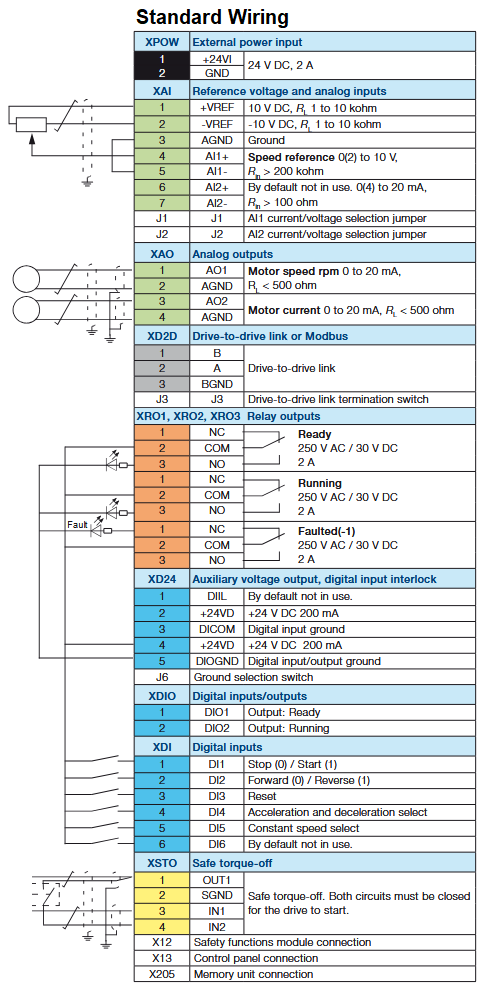
Wiring Details
Below image show terminal details:
Brake Resistance Details
| Model no. | R. Min | P.BR Max |
| 3-phase, 380 to 480 V | ohm | KW |
| ACS880-01-02A4-3 | 78 | 0.75 |
| ACS880-01-03A3-3 | 78 | 1.1 |
| ACS880-01-04A0-3 | 78 | 1.5 |
| ACS880-01-05A6-3 | 78 | 2.2 |
| ACS880-01-07A2-3 | 78 | 3 |
| ACS880-01-09A4-3 | 78 | 4 |
| ACS880-01-12A6-3 | 78 | 5.5 |
| ACS880-01-017A-3 | 39 | 7.5 |
| ACS880-01-025A-3 | 39 | 11 |
| ACS880-01-032A-3 | 19 | 15 |
| ACS880-01-038A-3 | 19 | 18.5 |
| ACS880-01-045A-3 | 13 | 22 |
| ACS880-01-061A-3 | 13 | 22 |
Faults & Alarms
Search from below list for ACS880 drive faults & alarms:
| Fault Code and Meaning | Cause and Remedy |
|---|---|
| 2281 Calibration | Cause: Measured offset of output phase current measurement or difference between output phase U2 and W2 current measurement is too great (the values are updated during current calibration). Remedy: Try performing the current calibration again (select Current measurement calibration at parameter 99.13). If the fault persists, contact your local ABB representative. |
| 2310 Overcurrent | Cause: Output current has exceeded internal fault limit. Remedy:
|
| 2330 Earth leakage | Cause: Drive has detected load unbalance typically due to earth fault in motor or motor cable. Remedy:
|
| 2340 Short circuit | Cause: Short-circuit in motor cable(s) or motor. Remedy:
|
| 2381 IGBT overload | Cause: Excessive IGBT junction to case temperature. This fault protects the IGBT(s) and can be activated by a short circuit in the motor cable. Remedy:
|
| 2391 BU current difference | Cause: AC phase current difference between parallel-connected inverter modules is excessive. Remedy:
|
| 2392 BU earth leakage | Cause: Total earth leakage of inverter modules is excessive. Remedy:
|
| 2E01 Earth leakage | Cause: IGBT supply unit has detected an earth fault. Remedy:
|
| 3000 Invalid voltage chain datapoints | Cause: Parametrization of the speed/torque limitation curve (in the DC voltage reference chain) are inconsistent. Remedy: Check that the speed points of the curve (defined by 29.70…29.79) are in increasing order. |
| 3130 Supply phase loss | Cause: Intermediate circuit DC voltage is oscillating due to missing input power line phase or blown fuse. Remedy:
|
| 3180 Charge relay lost | Cause: No acknowledgement received from charge relay. Remedy: Contact your local ABB representative. |
| 3181 Wiring or earth fault | Cause:
Remedy:
|
| 3210 DC link overvoltage | Cause: Excessive intermediate circuit DC voltage. Remedy:
|
| 3220 DC link undervoltage | Cause: Intermediate circuit DC voltage is not sufficient because of a missing supply phase, blown fuse or fault in the rectifier bridge. Remedy:
|
| 3280 Standby timeout | Cause: Automatic restart failed (see section Automatic restart). Remedy: Check the condition of the supply (voltage, cabling, fuses, switchgear). |
| 3291 DC voltage difference | Cause: Difference in DC voltages between parallel-connected inverter modules. Remedy: Check the auxiliary code (format XXXY YYZZ). “XXX” specifies the source of the first error. “YYY” specifies the module through which BCU control unit channel the fault was received. |
| 3381 Output phase loss | Cause: Motor circuit fault due to missing motor connection (all three phases are not connected). Remedy: Connect motor cable. |
| 3385 Autophasing | Cause: Autophasing routine (see section Autophasing) has failed. Remedy:
|
| 3E00 Input phase loss | Cause: Input phase loss detected by the IGBT bridge. Remedy:
|
| 4000 Motor cable overload | Cause: Calculated motor cable temperature has exceeded warning limit. Remedy:
|
| 4100 Ambient temperature | Cause: Drive module temperature is excessive. Remedy:
|
| 4110 Control board temperature | Cause: Control board temperature is too high. Remedy:
|
| 4210 IGBT overtemperature | Cause: Estimated drive IGBT temperature is excessive. Remedy:
|
| 4290 Cooling | Cause: Drive module temperature is excessive. Remedy: Check ambient temperature. If it exceeds 40 °C (104 °F), ensure that load current does not exceed derated load capacity of drive. See appropriate Hardware manual. Check drive module cooling air flow and fan operation. Check inside of cabinet and heatsink of drive module for dust pick-up. Clean whenever necessary. |
| 42F1 IGBT temperature | Cause: Drive IGBT temperature is excessive. Remedy: Check ambient conditions. Check air flow and fan operation. Check heatsink fins for dust pick-up. Check motor power against drive power. |
| 4310 Excess temperature | Cause: Power unit module temperature is excessive. Remedy: See A4B0 Excess temperature. |
| 4380 Excess temp difference | Cause: High temperature difference between the IGBTs of different phases. Remedy: See A4B1 Excess temperature difference (page 704). |
| 4981 External temperature 1 | Cause: Measured temperature 1 has exceeded fault limit. Remedy: Check the value of parameter 35.2 Measured temperature 1. Check the cooling of the motor (or other equipment whose temperature is being measured). Check the value of parameter 35.12 Temperature 1 fault limit. |
| 4982 External temperature 2 | Cause: Measured temperature 2 has exceeded fault limit. Remedy: Check the value of parameter 35.3 Measured temperature 2. Check the cooling of the motor (or other equipment whose temperature is being measured). Check the value of parameter 35.22 Temperature 2 fault limit. |
| 4990 FPTC not found | Cause: A thermistor protection module has been activated by parameter 35.30 but cannot be detected. Remedy: Power down the control unit and make sure that the module is properly inserted in the correct slot. The last digit of the auxiliary code identifies the slot. |
| 4991 Safe motor temperature 1 | Cause: The thermistor protection module installed in slot 1 indicates overtemperature. Remedy: Check the cooling of the motor. Check the motor load and drive ratings. Check the wiring of the temperature sensor. Repair wiring if faulty. Measure the resistance of the sensor. Replace sensor if faulty. |
| 4992 Safe motor temperature 2 | Cause: The thermistor protection module installed in slot 2 indicates overtemperature. Remedy: Check the cooling of the motor. Check the motor load and drive ratings. Check the wiring of the temperature sensor. Repair wiring if faulty. Measure the resistance of the sensor. Replace sensor if faulty. |
| 4993 Safe motor temperature 3 | Cause: The thermistor protection module installed in slot 3 indicates overtemperature. Remedy: Check the cooling of the motor. Check the motor load and drive ratings. Check the wiring of the temperature sensor. Repair wiring if faulty. Measure the resistance of the sensor. Replace sensor if faulty. |
| 5080 Fan | Cause: Cooling fan feedback missing. Remedy: See A581 Fan. |
| 5081 Auxiliary fan not running | Cause: An auxiliary cooling fan (connected to the fan connectors on the control unit) is stuck or disconnected. Remedy: See A582 Auxiliary fan not running. |
| 5090 STO hardware failure | Cause: Safe torque off hardware failure. Remedy: Contact your local ABB representative, quoting the auxiliary code. The code contains location information, especially with parallel-connected inverter modules. When converted into a 32-bit binary number, the bits of the code indicate the following: 31…28: Number of faulty inverter module (0…11 decimal). 1111: STO_ACT states of control unit and inverter modules in conflict. 27: STO_ACT state of inverter modules. 26: STO_ACT state of control unit. 25: STO1 of control unit. 24: STO2 of control unit. 23…12: STO1 of inverter modules 12…1 (Bits of non-existing modules set to 1). 11…0: STO2 of inverter modules 12…1 (Bits of non-existing modules set to 1). |
| 5091 Safe torque off | Cause: Safe torque off function is active, i.e. safety circuit signal(s) connected to connector XSTO is broken during start or run. Remedy: Check safe torque off circuit connections. For more information, see appropriate drive hardware manual and description of parameter 31.22 STO indication run/stop (page 434). |
| 5092 PU logic error | Cause: Power unit memory has cleared. Remedy: Cycle the power to the drive. If the control unit is externally powered, also reboot the control unit (using parameter 96.8 Control board boot) or by cycling its power. If the problem persists, contact your local ABB representative. |
| 5093 Rating ID mismatch | Cause: The hardware of the drive does not match the information stored in the memory unit. This may occur eg. after a firmware update or memory unit replacement. Remedy: Cycle the power to the drive. Check the auxiliary code (format 0X0Y). “X” indicates the first faulty PU channel in hexadecimal (1…C). With a ZCU control unit, “X” can be 1 or 2 but this is irrelevant to the fault. “Y” indicates the auxiliary code category (e.g., 1=PU and CU ratings not same, 2=Rating ID changed, etc.). |
| 5094 Measurement circuit temperature | Cause: Problem with internal temperature measurement of the drive. Remedy: See A5EA Measurement circuit temperature (page 705). |
| 5681 PU communication | Cause: The way the control unit is powered does not correspond to parameter setting. Communication errors detected between the drive control unit and the power unit. Remedy: Check setting of 95.4 Control board supply. Check the connection between the control unit and the power unit. Check the auxiliary code (format XXXY YYZZ). With parallel-connected modules, “Y YY” specifies the affected BCU control unit channel. “ZZ” specifies the error source. “XXX” specifies the transmitter FIFO error code. |
| 5682 Power unit lost | Cause: Connection between the drive control unit and the power unit is lost. Remedy: Check the connection between the control unit and the power unit. |
| 5690 PU communication internal | Cause: Internal communication error. Remedy: Contact your local ABB representative. |
| 5691 Measurement circuit ADC | Cause: Measurement circuit fault. Remedy: If the control unit is externally powered, check the setting of parameter 95.4 Control board supply. If the problem persists, contact your local ABB representative, quoting the auxiliary code. |
| 5692 PU board powerfail | Cause: Power unit power supply failure. Remedy: Check the auxiliary code (format ZZZY YYXX). “YY Y” specifies the affected inverter module. “XX” specifies the affected power supply (1: Power supply 1, 2: Power supply 2, 3: both supplies). |
| 5693 Measurement circuit DFF | Cause: Measurement circuit fault. Remedy: Contact your local ABB representative, quoting the auxiliary code. |
| 5694 PU communication conf | Cause: Number of connected power modules differs from expected. Remedy: Check setting of 95.31 Parallel type configuration. Cycle the power to the drive. If the control unit is externally powered, also reboot the control unit (using parameter 96.8 Control board boot) or by cycling its power. If the problem persists, contact your local ABB representative. |
| 5695 Reduced run | Cause: Number of inverter modules detected does not match the value of parameter 95.13 Reduced run mode. Remedy: Check that the value of 95.13 Reduced run mode corresponds to the number of inverter modules present. Check that the modules present are powered from the DC bus and connected by fiber optic cables to the BCU control unit. If all modules of the inverter unit are in fact available, check that parameter 95.13 Reduced run mode is set to 0. |
| 5696 PU state feedback | Cause: State feedback from output phases does not match control signals. Remedy: Contact your local ABB representative, quoting the auxiliary code. |
| 5697 Charging feedback | Cause: Incorrect parameter setting. The charging switch and DC switch were operated out of sequence, or a start command was issued before the unit was ready. Charging circuit fault. Remedy: Check the setting of 95.9 Switch fuse controller. The normal power-up sequence is: 1. Close charging switch. 2. After charging finishes, close DC switch. 3. Open charging switch. Check the charging circuit. With a frame R6i/R7i inverter module, check auxiliary code “FA”. Check the wiring and condition of brake resistor. |
| 5698 Unknown PU fault | Cause: Unidentified power unit logic fault. Remedy: Check power unit logic and firmware compatibility. Contact your local ABB representative. |
| 6000 Internal SW error | Cause: Internal error. Remedy: Contact your local ABB representative, quoting the auxiliary code. |
| 6181 FPGA version incompatible | Cause: Firmware and FPGA file version in the power unit are incompatible. Update of power unit logic failed. Remedy: Reboot the control unit (using parameter 96.8 Control board boot) or by cycling power. If the problem persists, contact your local ABB representative. Retry update. Check the auxiliary code to identify FPGA version compatibility (format: XXYYZZ). |
| 6200 Checksum mismatch | Cause: The calculated parameter checksum does not match any enabled reference checksum. Remedy: See A686 Checksum mismatch. |
| 6306 FBA A mapping file | Cause: Fieldbus adapter A mapping file read error. Remedy: Contact your local ABB representative. |
| 6307 FBA B mapping file | Cause: Fieldbus adapter B mapping file read error. Remedy: Contact your local ABB representative. |
| 6481 Task overload | Cause: Internal fault. Remedy: Reboot the control unit (using parameter 96.8 Control board boot) or by cycling power. If the problem persists, contact your local ABB representative. |
| 6487 Stack overflow | Cause: Internal fault. Remedy: Reboot the control unit (using parameter 96.8 Control board boot) or by cycling power. If the problem persists, contact your local ABB representative. |
| 64A1 Internal file load | Cause: File read error. Remedy: Reboot the control unit (using parameter 96.8 Control board boot) or by cycling power. If the problem persists, contact your local ABB representative. |
| 64A2 Internal record load | Cause: Internal record load error. Remedy: Contact your local ABB representative. |
| 64A3 Application loading | Cause: Application file incompatible or corrupted. Remedy: Check the auxiliary code. See actions for each code below:
|
| 64A5 Licensing fault | Cause: Running the control program is prevented either because a restrictive license exists, or because a required license is missing. Remedy: Record the auxiliary codes of all active licensing faults and contact your product vendor for further instructions. |
| 64A6 Adaptive program | Cause: Error running the adaptive program. Remedy: Check the auxiliary code (format XXXX YYYY). “XXXX” specifies the number of the function block. “YYYY” indicates the problem:
|
| 64B0 Memory unit detached | Cause: The memory unit was detached when the control unit was powered. Remedy: Switch off the power to the control unit and reinstall the memory unit.
|
| 64B1 Internal SSW fault | Cause: Internal fault. Remedy: Reboot the control unit (using parameter 96.8 Control board boot) or by cycling power. If the problem persists, contact your local ABB representative. |
| 64B2 User set fault | Cause: Loading of user parameter set failed because:
Remedy: Ensure that a valid user parameter set exists. Reload if uncertain. |
| 64E1 Kernel overload | Cause: Operating system error. Remedy: Reboot the control unit (using parameter 96.8 Control board boot) or by cycling power. If the problem persists, contact your local ABB representative. |
| 64FF Fault reset | Cause: Informative fault. Remedy: An active fault has been reset. |
| 6581 Parameter system | Cause: Parameter load or save failed. Remedy: Try forcing a save using parameter 96.7 Parameter save manually. Retry. |
| 6591 Backup/Restore Timeout | Cause: Parameter load or save timeout caused by communication break between drive and control panel, or control panel and PC tool. Remedy: Check the communication between drive and control panel or PC. Retry. |
| 65A1 FBA A parameter conflict | Cause: The drive does not have a functionality requested by PLC, or requested functionality has not been activated. Remedy: Check PLC programming. Check settings of parameter groups 50 Fieldbus adapter (FBA) and 51 FBA A settings. |
| 65A2 FBA B parameter conflict | Cause: The drive does not have a functionality requested by PLC, or requested functionality has not been activated. Remedy: Check PLC programming. Check settings of parameter groups 50 Fieldbus adapter (FBA) and 54 FBA B settings. |
| 65B1 Reference source parametrization | Cause: A reference source is simultaneously connected to multiple parameters with different units. Remedy: See A6DA Reference source parametrization (page 709). |
| 6681 EFB communication loss | Cause: Communication break in embedded fieldbus (EFB) communication. Remedy: Check the status of the fieldbus master (online/offline/error etc.). Check cable connections to the XD2D connector on the control unit. |
| 6682 EFB configuration file | Cause: Embedded fieldbus (EFB) configuration file could not be read. Remedy: Contact your local ABB representative. |
| 6683 EFB invalid parameterization | Cause: Embedded fieldbus (EFB) parameter settings inconsistent or not compatible with selected protocol. Remedy: Check the settings in parameter group 58 Embedded fieldbus. |
| 6684 EFB load fault | Cause: Embedded fieldbus (EFB) protocol firmware could not be loaded, or version mismatch between EFB protocol firmware and drive firmware. Remedy: Contact your local ABB representative. |
| 6881 Text data overflow | Cause: Internal fault. Remedy: Reset the fault. Contact your local ABB representative if the fault persists. |
| 6882 Text 32-bit table overflow | Cause: Internal fault. Remedy: Reset the fault. Contact your local ABB representative if the fault persists. |
| 6883 Text 64-bit table overflow | Cause: Internal fault. Remedy: Reset the fault. Contact your local ABB representative if the fault persists. |
| 6885 Text file overflow | Cause: Internal fault. Remedy: Reset the fault. Contact your local ABB representative if the fault persists. |
| 7080 Option module comm loss | Cause: Communication between drive and an option module is lost. Remedy: See A798 Encoder option comm loss (page 711). |
| 7081 Control panel loss | Cause: Control panel (or PC tool) has stopped communicating. Remedy: Check PC tool or control panel connection. Check control panel connector. Disconnect and reconnect the control panel. |
| 7082 Ext I/O comm loss | Cause: The I/O extension module types specified by parameters do not match the detected configuration. Remedy: Check the auxiliary code. The code specifies the I/O port used: 0=Panel, 1=Fieldbus A, 2=Fieldbus B, 3=Ethernet, 4=D2D/EFB. See A799. |
| 7083 Panel reference conflict | Cause: Use of saved control panel reference in multiple control modes attempted. Remedy: The control panel reference can only be saved for one reference type at a time. Consider using a copied reference instead (see reference selection parameter). |
| 7084 Panel/PC tool version conflict | Cause: The current version of the control panel and/or PC tool does not support a function (e.g. older panel versions). Remedy: Update control panel and/or PC tool. Contact your local ABB representative if necessary. |
| 7085 Incompatible option module | Cause: Option module not supported (e.g., Fxxx-xx-M fieldbus adapter modules are not supported). Remedy: Check the auxiliary code to identify the interface (1: Fieldbus A, 2: Fieldbus B). Replace module with supported type. Remove FSO-xx module to clear fault if unsupported. |
| 7121 Motor stall | Cause: Motor is operating in stall region because of e.g. excessive load or insufficient motor power. Remedy: Check motor load and drive ratings. Check fault function parameters. |
| 7122 Motor overload | Cause: Motor current is too high. Remedy: Check for overloaded motor. Adjust the parameters used for the motor overload function (35.51…35.53 and 35.55…35.56). |
| 7181 Brake resistor | Cause: DC overvoltage detected during braking. Remedy: Check that a brake resistor has been connected. Check the condition of the brake resistor. Check the dimensioning of the brake chopper and resistor. |
| 7183 BR excess temperature | Cause: Brake resistor temperature has exceeded fault limit defined by parameter 43.11 Brake resistor fault limit. Remedy: Stop drive. Let resistor cool down. Check resistor overload protection function settings (parameter group 43). Check fault limit setting (43.11). Check that braking cycle meets allowed limits. |
| 7184 Brake resistor wiring | Cause: Brake resistor short circuit or brake chopper control fault. Remedy: Check brake chopper and brake resistor connection. Ensure brake resistor is not damaged. Reboot control unit or cycle power. |
| 7191 BC short circuit | Cause: Short circuit in brake chopper IGBT. Remedy: Ensure brake resistor is connected and not damaged. Check electrical specifications. Replace brake chopper if replaceable. Reboot control unit or cycle power. |
| 7192 BC IGBT excess temperature | Cause: Brake chopper IGBT temperature has exceeded internal fault limit. Remedy: Let chopper cool down. Check for excessive ambient temperature, cooling fan failure, or obstructions. Check dimensioning. Check group 43 settings. |
| 71A2 Mech brake closing failed | Cause: Mechanical brake control fault. Activated e.g. if brake acknowledgement is not as expected during brake closing. Remedy: Check mechanical brake connection. Check mechanical brake settings in parameter group 44. Check that acknowledgement signal matches actual status of brake. |
| 71A3 Mech brake opening failed | Cause: Mechanical brake control fault. Activated e.g. if brake acknowledgement is not as expected during brake opening. Remedy: Check mechanical brake connection. Check mechanical brake settings in parameter group 44. Check that acknowledgement signal matches actual status of brake. |
| 71A5 Mech brk opening not allowed | Cause: Open conditions of mechanical brake cannot be fulfilled (e.g. prevented by parameter 44.11). Remedy: Check mechanical brake settings in parameter group 44 (especially 44.11). Check that acknowledgement signal matches actual status of brake. |
| 71B1 Motor fan | Cause: No feedback received from external fan. Remedy:
|
| 7301 Motor speed feedback | Cause: No motor speed feedback received. Remedy:
|
| 7310 Overspeed | Cause: Motor is turning faster than highest allowed speed due to incorrectly set minimum/maximum speed, insufficient braking torque or changes in load when using torque reference. Incorrect estimated speed. Remedy:
|
| 7380 Encoder internal | Cause: Internal fault. Remedy:
|
| 7381 Encoder | Cause: Encoder feedback fault. Remedy:
|
| 73A0 Speed fbk configuration | Cause: Speed feedback configuration incorrect. Remedy:
|
| 73A1 Load position feedback | Cause: No load position feedback received. Remedy:
|
| 73B0 Emergency ramp failed | Cause: Emergency stop did not finish within expected time. Remedy:
|
| 73B1 Stop failed | Cause: Ramp stop did not finish within expected time. Remedy:
|
| 73F0 Overfrequency | Cause: Maximum allowed output frequency exceeded. Remedy:
|
| 7510 FBA A communication | Cause: Cyclical communication between drive and fieldbus adapter module A or between PLC and fieldbus adapter module A is lost. Remedy:
|
| 7520 FBA B communication | Cause: Cyclical communication between drive and fieldbus adapter module B or between PLC and fieldbus adapter module B is lost. Remedy:
|
| 7580 INU-LSU comm loss | Cause: DDCS (fiber optic) communication between converters (for example, the inverter unit and the supply unit) is lost. Remedy:
|
| 7581 DDCS controller comm loss | Cause: DDCS (fiber optic) communication between drive and external controller is lost. Remedy:
|
| 7582 M/F comm loss | Cause: Master/follower communication is lost. Remedy:
|
| 7583 Line side unit faulted | Cause: The supply unit (or other converter) connected to the inverter unit has generated a fault. Remedy:
|
| 7584 LSU charge failed | Cause: The supply unit was not ready (ie. the main contactor/breaker could not be closed) within expected time. Remedy:
|
| 8001 ULC underload | Cause: Selected signal has fallen below the user underload curve. Remedy:
|
| 8002 ULC overload | Cause: Selected signal has exceeded the user overload curve. Remedy:
|
| 80A0 AI Supervision | Cause: An analog signal is outside the limits specified for the analog input. Remedy:
|
| 80B0 Signal supervision | Cause: Fault generated by the signal supervision 1 function. Remedy:
|
| 80B1 Signal supervision 2 | Cause: Fault generated by the signal supervision 2 function. Remedy:
|
| 80B2 Signal supervision 3 | Cause: Fault generated by the signal supervision 3 function. Remedy:
|
| 8E12 Fan speed | Cause: Fan speed is under limit (parameter 206.07). Remedy:
|
| 8E13 I/O module version mismatch | Cause: Communication services of the CIO-01 module are incompatible with the firmware version on the control unit. Remedy:
|
| 8E14 CIO MCB monitoring | Cause: Fault related to miniature circuit breaker. Some of the bits of the MCB status word are 0. Remedy:
|
| 8E15 CIO fuse monitoring | Cause: Fault related to fuses. Some of the bits of the fuse status word are 0. Remedy:
|
| 8E17 CIO DI8 monitoring | Cause: Fault related to digital input DI8. Remedy:
|
| 9081 External fault 1 | Cause: Fault in external device 1. Remedy:
|
| 9082 External fault 2 | Cause: Fault in external device 2. Remedy:
|
| 9083 External fault 3 | Cause: Fault in external device 3. Remedy:
|
| 9084 External fault 4 | Cause: Fault in external device 4. Remedy:
|
| 9085 External fault 5 | Cause: Fault in external device 5. Remedy:
|
| A2A1 Current calibration | Cause: Current offset and gain measurement calibration will occur at next start. Remedy:
|
| A2B3 Earth leakage | Cause: Drive has detected load unbalance typically due to earth fault in motor or motor cable. Remedy:
|
| A2B4 Short circuit | Cause: Short-circuit in motor cable(s) or motor. Remedy:
|
| A2BA IGBT overload | Cause: Excessive IGBT junction to case temperature. This warning protects the IGBT(s) and can be activated by a short circuit in the motor cable. Remedy:
|
| A3A1 DC link overvoltage | Cause: Intermediate circuit DC voltage too high (when the drive is stopped). Remedy: Check the supply voltage setting (parameter 95.1 Supply voltage). Note that the wrong setting of the parameter may cause the motor to rush uncontrollably, or may overload the brake chopper or resistor.
|
| A3A2 DC link undervoltage | Cause: Intermediate circuit DC voltage too low (when the drive is stopped). Remedy: Check the supply voltage setting (parameter 95.1 Supply voltage). Note that the wrong setting of the parameter may cause the motor to rush uncontrollably, or may overload the brake chopper or resistor.
|
| A3AA DC not charged | Cause: The voltage of the intermediate DC circuit has not yet risen to operating level. Remedy: Check the supply voltage setting (parameter 95.1 Supply voltage).
|
| A480 Motor cable overload | Cause: Calculated motor cable temperature has exceeded warning limit. Remedy:
|
| A490 Incorrect temperature sensor setup | Cause: Problem with motor temperature measurement. Check the auxiliary code (format 0XYY ZZZZ). Remedy: Check the auxiliary code to identify the specific issue:
|
| A491 External temperature 1 | Cause: Measured temperature 1 has exceeded warning limit. Remedy: Check the value of parameter 35.2 Measured temperature 1.
|
| A492 External temperature 2 | Cause: Measured temperature 2 has exceeded warning limit. Remedy: Check the value of parameter 35.3 Measured temperature 2.
|
| A497 Motor temperature 1 | Cause: The thermistor protection module installed in slot 1 indicates overtemperature. Remedy:
|
| A498 Motor temperature 2 | Cause: The thermistor protection module installed in slot 2 indicates overtemperature. Remedy:
|
| A499 Motor temperature 3 | Cause: The thermistor protection module installed in slot 3 indicates overtemperature. Remedy:
|
| A4A0 Control board temperature | Cause: Control unit temperature is excessive. Remedy: Check the auxiliary code.
|
| A4A9 Cooling | Cause: Drive module temperature is excessive. Remedy:
|
| A4B0 Excess temperature | Cause: Power unit temperature is excessive. Remedy:
|
| A4B1 Excess temperature difference | Cause: High temperature difference between the IGBTs of different phases. Remedy:
|
| A4F6 IGBT temperature | Cause: Drive IGBT temperature is excessive. Remedy:
|
| A580 PU communication | Cause: Communication errors detected between the drive control unit and the power unit. Remedy:
|
| A581 Fan | Cause: Cooling fan feedback missing. Remedy:
|
| A582 Auxiliary fan not running | Cause: An auxiliary cooling fan (connected to the fan connectors on the control unit) is stuck or disconnected. Remedy: The auxiliary code identifies the fan (1: Auxiliary fan 1, 2: Auxiliary fan 2).
|
| A5A0 Safe torque off | Cause: Safe torque off function is active, i.e. safety circuit signal(s) connected to connector XSTO is lost. Remedy: Check safety circuit connections. For more information, see appropriate drive hardware manual and description of parameter 31.22 STO indication run/stop. |
| A5EA Measurement circuit temperature | Cause: Problem with internal temperature measurement of the drive. Remedy: Check the auxiliary code (format XXXY YYZZ). “Y YY” specifies through which BCU control unit channel the fault was received. “ZZ” specifies the location (e.g., U-phase IGBT, Power supply board). |
| A5EB PU board powerfail | Cause: Power unit power supply failure. Remedy: Contact your local ABB representative. |
| A5EC PU communication internal | Cause: Communication errors detected between the drive control unit and the power unit. Remedy: Check the connections between the drive control unit and the power unit. |
| A5ED Measurement circuit ADC | Cause: Problem with measurement circuit of power unit (analog to digital converter). Remedy: Contact your local ABB representative. |
| A5EE Measurement circuit DFF | Cause: Problem with current or voltage measurement of power unit. Remedy: Contact your local ABB representative. |
| A5EF PU state feedback | Cause: State feedback from output phases does not match control signals. Remedy: Contact your local ABB representative. |
| A5F0 Charging feedback | Cause: Charging in progress. Remedy: Informative warning. Wait until charging finishes before starting the inverter unit. |
| A5F3 Switching frequency below requested | Cause: Adequate motor control at requested output frequency cannot be reached because of limited switching frequency (eg. by parameter 95.15). Remedy: Informative warning. |
| A5F4 Control unit battery | Cause: The battery of the control unit is low. Remedy: Replace control unit battery. This warning can be suppressed using parameter 31.40. |
| A682 Flash erase speed exceeded | Cause: The flash memory (in the memory unit) has been erased too frequently, compromising the lifetime of the memory. Remedy:
|
| A683 Data saving to power unit | Cause: An error in saving data to the power unit. Remedy: Check the auxiliary code.
|
| A684 SD card | Cause: Error related to SD card used to store data (BCU control unit only). Remedy: Check the auxiliary code:
|
| A685 Power fail saving | Cause: Power fail saving is requested too frequently. Because of the limited saving interval, some of the requests do not trigger the saving and power fail data may be lost. This may be caused by DC voltage oscillation. Remedy: Check the supply voltage. |
| A686 Checksum mismatch | Cause: The calculated parameter checksum does not match any enabled reference checksum. Remedy:
|
| A687 Checksum configuration | Cause: An action has been defined for a parameter checksum mismatch but the feature has not been configured. Remedy: Contact your local ABB representative for configuring the feature, or disable the feature in 96.54 Checksum action. |
| A688 Parameter map configuration | Cause: Too much data in parameter mapping table created in Drive customizer. Remedy: See the Drive customizer PC tool user’s manual (3AUA0000104167 [English]). |
| A689 Mapped parameter value cut | Cause: Parameter value saturated eg. by the scaling specified in parameter mapping table (created in Drive customizer). Remedy: Check parameter scaling and format in parameter mapping table. See the Drive customizer PC tool user’s manual. |
| A6A4 Motor nominal value | Cause: The motor parameters are set incorrectly. The drive is not dimensioned correctly. Remedy: Check the auxiliary code:
|
| A6A5 No motor data | Cause: Parameters in group 99 have not been set. Remedy: Check that all the required parameters in group 99 have been set. Note: It is normal for this warning to appear during the start-up. |
| A6A6 Supply voltage unselected | Cause: The supply voltage has not been defined. Remedy: Set supply voltage in parameter 95.1 Supply voltage. |
| A6B0 User lock open | Cause: The user lock is open, ie. user lock configuration parameters 96.100…96.102 are visible. Remedy: Close the user lock by entering an invalid pass code in parameter 96.2 Pass code. See section User lock. |
| A6B1 User pass code not confirmed | Cause: A new user pass code has been entered in parameter 96.100 but not confirmed in 96.101. Remedy: Confirm the new pass code by entering the same code in 96.101. To cancel, close the user lock without confirming the new code. |
| A6D1 FBA A parameter conflict | Cause: The drive does not have a functionality requested by a PLC, or requested functionality has not been activated. Remedy:
|
| A6D2 FBA B Parameter conflict | Cause: The drive does not have a functionality requested by a PLC, or requested functionality has not been activated. Remedy:
|
| A6DA Reference source parametrization | Cause: A reference source is simultaneously connected to multiple parameters with different units. Remedy:
|
| A6E5 AI parametrization | Cause: The current/voltage hardware setting of an analog input does not correspond to parameter settings. Remedy:
|
| A6E6 ULC configuration | Cause: User load curve configuration error. Remedy: Check the auxiliary code (format XXXX ZZZZ):
|
| A880 Motor bearing | Cause: Warning generated by an ontime timer or a value counter. Remedy: Check the auxiliary code. Check the source of the warning corresponding to the code:
|
| A881 Output relay | Cause: Warning generated by an edge counter. Programmable warnings: 33.35 Edge counter 1 warn message; 33.45 Edge counter 2 warn message. Remedy: Check the auxiliary code. Check the source of the warning corresponding to the code:
|
| A882 Motor starts | Cause: Warning generated by an edge counter. Programmable warnings: 33.35 Edge counter 1 warn message; 33.45 Edge counter 2 warn message. Remedy: Check the auxiliary code. Check the source of the warning corresponding to the code:
|
| A883 Power ups | Cause: Warning generated by an edge counter. Programmable warnings: 33.35 Edge counter 1 warn message; 33.45 Edge counter 2 warn message. Remedy: Check the auxiliary code. Check the source of the warning corresponding to the code:
|
| A884 Main contactor | Cause: Warning generated by an edge counter. Programmable warnings: 33.35 Edge counter 1 warn message; 33.45 Edge counter 2 warn message. Remedy: Check the auxiliary code. Check the source of the warning corresponding to the code:
|
| A885 DC charge | Cause: Warning generated by an edge counter. Programmable warnings: 33.35 Edge counter 1 warn message; 33.45 Edge counter 2 warn message. Remedy: Check the auxiliary code. Check the source of the warning corresponding to the code:
|
| A886 On-Time 1 | Cause: Warning generated by on-time timer 1. Remedy: Check the source of the warning (parameter 33.13 On-time 1 source). |
| A887 On-Time 2 | Cause: Warning generated by on-time timer 2. Remedy: Check the source of the warning (parameter 33.23 On-time 2 source). |
| A888 Edge counter 1 | Cause: Warning generated by edge counter 1. Remedy: Check the source of the warning (parameter 33.33 Edge counter 1 source). |
| A889 Edge counter 2 | Cause: Warning generated by edge counter 2. Remedy: Check the source of the warning (parameter 33.43 Edge counter 2 source). |
| A88A Value counter 1 | Cause: Warning generated by value counter 1. Remedy: Check the source of the warning (parameter 33.53 Value counter 1 source). |
| A88B Value counter 2 | Cause: Warning generated by value counter 2. Remedy: Check the source of the warning (parameter 33.63 Value counter 2 source). |
| A88C Device clean | Cause: Warning generated by an ontime timer. Programmable warnings: 33.14 On-time 1 warn message; 33.24 On-time 2 warn message. Remedy: Check the auxiliary code. Check the source of the warning corresponding to the code:
|
| A88D DC capacitor | Cause: Warning generated by an ontime timer. Programmable warnings: 33.14 On-time 1 warn message; 33.24 On-time 2 warn message. Remedy: Check the auxiliary code. Check the source of the warning corresponding to the code:
|
| A88E Cabinet fan | Cause: Warning generated by an ontime timer. Programmable warnings: 33.14 On-time 1 warn message; 33.24 On-time 2 warn message. Remedy: Check the auxiliary code. Check the source of the warning corresponding to the code:
|
| A88F Cooling fan | Cause: Warning generated by an ontime timer. Programmable warnings: 33.14 On-time 1 warn message; 33.24 On-time 2 warn message. Remedy: Check the auxiliary code. Check the source of the warning corresponding to the code:
|
| A890 Additional cooling fan | Cause: Warning generated by an ontime timer. Programmable warnings: 33.14 On-time 1 warn message; 33.24 On-time 2 warn message. Remedy: Check the auxiliary code. Check the source of the warning corresponding to the code:
|
| A8A0 AI Supervised Warning | Cause: An analog signal is outside the limits specified for the analog input. Remedy: Check the auxiliary code (format XYY). “X” specifies the location of the input (0: AI on control unit; 1: I/O extension module 1, etc.), “YY” specifies the input and limit:
Check signal level at the analog input. Check the wiring connected to the input. Check the minimum and maximum limits of the input in parameter group 12 Standard AI, 14 I/O extension module 1, 15 I/O extension module 2 or 16 I/O extension module 3. |
| A8B0 Signal supervision | Cause: Warning generated by the signal supervision 1 function. Remedy: Check the source of the warning (parameter 32.7 Supervision 1 signal). |
| A8B1 Signal supervision 2 | Cause: Warning generated by the signal supervision 2 function. Remedy: Check the source of the warning (parameter 32.17 Supervision 2 signal). |
| A8B2 Signal supervision 3 | Cause: Warning generated by the signal supervision 3 function. Remedy: Check the source of the warning (parameter 32.27 Supervision 3 signal). |
| A8BE ULC overload | Cause: Selected signal has exceeded the user overload curve. Remedy: Check for any operating conditions increasing the monitored signal (for example, the loading of the motor if the torque or current is being monitored). Check the definition of the load curve (parameter group 37 User load curve). |
| A8BF ULC underload | Cause: Selected signal has fallen below the user underload curve. Remedy: Check for any operating conditions decreasing the monitored signal (for example, loss of load if the torque or current is being monitored). Check the definition of the load curve (parameter group 37 User load curve). |
| A8C0 Fan service counter | Cause: A cooling fan has reached the end of its estimated lifetime. See parameters 5.41 and 5.42. Remedy: Check the auxiliary code. The code indicates which fan is to be replaced:
Refer to the hardware manual of the drive for fan replacement instructions. |
| A981 External warning 1 | Cause: Fault in external device 1. Remedy: Check the external device. Check setting of parameter 31.1 External event 1 source. |
| A982 External warning 2 | Cause: Fault in external device 2. Remedy: Check the external device. Check setting of parameter 31.3 External event 2 source. |
| A983 External warning 3 | Cause: Fault in external device 3. Remedy: Check the external device. Check setting of parameter 31.5 External event 3 source. |
| A984 External warning 4 | Cause: Fault in external device 4. Remedy: Check the external device. Check setting of parameter 31.7 External event 4 source. |
| A985 External warning 5 | Cause: Fault in external device 5. Remedy: Check the external device. Check setting of parameter 31.9 External event 5 source. |
| AE90 I/O bus communication | Cause: Communication break noticed on I/O bus. Remedy: Check I/O bus wiring, powering of the nodes and node number settings on the CIO-01 module. Parameters of parameter group 208 I/O bus diagnostics can be used to identify the nodes that are timing out. |
| AE91 Fan lifetime exceeded | Cause: Warning limit for fan lifetime (parameter 206.08) has been exceeded. Remedy: See the auxiliary code for indication of module IDs that contain fans that have exceeded their lifespan. Auxiliary code is a bit word where bit 0 indicates CIO-01 module assigned to node ID 1. Replace the failing fan and reset the fan data via parameter group 207 I/O bus service. |
| AE92 Fan speed | Cause: Fan speed is under limit (parameter 206.06). Remedy: Check fan feedback. See parameters 206.30…206.33 for individual failing fans. |
| AE93 Fan speed feedback error | Cause: Error in fan speed feedback. Remedy: See the auxiliary code for node(s) giving faulty feedback indication for fan(s). Auxiliary code is a bit word where bit 0 indicates CIO-01 module assigned to node ID 1. Check fan feedback. Verify the identification run results against the tachometer pulse count of the fan feedback. |
| AE94 CIO MCB monitoring | Cause: Warning related to miniature circuit breaker. Some of the bits of the MCB status word are 0. Remedy: Check miniature circuit breaker and digital input DI5. |
| AE95 CIO fuse monitoring | Cause: Warning related to fuses. Some of the bits of the fuse status word are 0. Remedy: Check fuses and digital input DI6. |
| AE97 CIO DI8 monitoring | Cause: Warning related to digital input DI8. Remedy: Check digital input DI8. |
| AF80 INU-LSU comm loss | Cause: DDCS (fiber optic) communication between converters (for example, the inverter unit and the supply unit) is lost. Note that the inverter unit will continue operating based on the status information that was last received from the other converter. Remedy: Check status of other converter (parameters 06.36 and 06.39). Check settings of parameter group 60 DDCS communication. Check the corresponding settings in the control program of the other converter. Check cable connections. If necessary, replace cables. |
| AF85 Line side unit warning | Cause: The supply unit (or other converter) has generated a warning. Remedy: The auxiliary code specifies the original warning code in the supply unit control program. See section Auxiliary codes for line-side converter warnings. |
| AF8C Process PID sleep mode | Cause: The drive is entering sleep mode. Remedy: Informative warning. |
| AF90 Speed controller autotuning | Cause: The speed controller autotune routine did not complete successfully. Remedy: Check the auxiliary code (format XXXX YYYY). “YYYY” indicates the problem:
|
| AFAA Autoreset | Cause: A fault is about to be autoreset. Remedy: Informative warning. See the settings in parameter group 31 Fault functions. |
| AFE1 Emergency stop (off2) | Cause: Drive has received an emergency stop (mode selection off2) command. Follower drive in a master/follower configuration: Drive has received a stop command from the master. Remedy: Check that it is safe to continue operation. Reset the source of the emergency stop signal (such as an emergency stop push button). Restart drive. If the emergency stop was unintentional, check the source of the stop signal. Informative warning: After stopping on a ramp stop (Off1 or Off3) command, the master sends a short, 10-millisecond coast stop (Off2) command to the follower(s). |
| AFE2 Emergency stop (off1 or off3) | Cause: Drive has received an emergency stop (mode selection Off1 or Off3) command. Remedy: Check that it is safe to continue operation. Reset the source of the emergency stop signal (such as an emergency stop push button). Restart drive. If the emergency stop was unintentional, check the source of the stop signal. |
| AFE7 Follower | Cause: A follower drive has tripped. Remedy: Check the auxiliary code. Add 2 to the code to find out the node address of the faulted drive. Correct the fault in the follower drive. |
| AFEA Enable start signal missing | Cause: No enable start signal received. Remedy: Check the setting of (and the source selected by) parameter 20.19 Enable start command. |
| AFEB Run enable missing | Cause: No run enable signal is received. Remedy: Check setting of parameter 20.12 Run enable 1 source. Switch signal on (e.g. in the fieldbus Control Word) or check wiring of selected source. |
| AFEC External power signal missing | Cause: 95.4 Control board supply is set to External 24V but no voltage is connected to the XPOW connector of the control unit. Remedy: Check the external 24 V DC power supply to the control unit, or change the setting of parameter 95.4. |
| AFF6 Identification run selected | Cause: Motor ID run will occur at next start, or is in progress. Remedy: Informative warning. |
| AFF7 Autophasing | Cause: Autophasing will occur at next start. Remedy: Informative warning. |
| B5A0 STO event | Cause: Safe torque off function is active, i.e. safety circuit signal(s) connected to connector XSTO is lost. Remedy:
|
| B5A2 Power up | Cause: The drive has been powered up. Remedy:
|
| B5A4 SW internal diagnostics | Cause: Control unit rebooted unexpectedly. Remedy:
|
| B5F6 ID run done | Cause: ID run completed. Remedy:
|
| B680 SW internal diagnostics | Cause: SW internal malfunction. Remedy:
|
| B686 Checksum mismatch | Cause: The calculated parameter checksum does not match any enabled reference checksum. Remedy:
|
| D100 Torque prove | Cause: Drive was not able to provide sufficient torque during Torque proving. The pre-magnetizing time mode is wrong or too short. Remedy:
|
| D101 Brake slip | Cause: Brake slipped during Torque proving. Remedy:
|
| D102 Brake safe closure | Cause: Start command is active, the actual speed is below the limit defined with parameter 44.208 Safety close speed, and the delay defined with parameter 44.209 Safety close delay has elapsed. Remedy:
|
| D103 Hoist speed opt settings | Cause: Parameters settings for Hoist speed optimization are incorrect. Remedy:
|
| D104 Over speed | Cause: Motor speed has exceeded the motor overspeed level (31.200), and the delay defined with parameter 31.201 has elapsed. Remedy:
|
| D105 Speed match | Cause: Motor speed has exceeded the steady state deviation level (par. 74.2) or the ramping state deviation level (par. 74.3), and the delay defined with parameter 74.4 has elapsed. Remedy:
|
| D106 Inverter overload | Cause: Drive has exceeded the inverter current or torque limits, and the delay defined with parameter 31.204 has elapsed. The fault condition is checked only when the generating power is more than 10% of the motor nominal power and the actual speed is greater than 5% of the motor synchronous speed. Remedy:
|
| D107 ID run and remote | Cause: Motor ID run was requested when the drive was in external control. Remedy:
|
| D108 End limits I/O error | Cause: Both End limits 1 and 2 inputs are active simultaneously. Remedy:
|
| D109 Toggle bit supervision flt | Cause: Communication loss occurred between the overriding system and the drive. Time between two consecutive toggle bit rising edges from overriding system is longer than the time set in parameter 31.213. Remedy:
|
| D10A Brake control selected | Cause: Mechanical brake control was inactive when the Conical motor control function was enabled. Remedy:
|
| D10B Synchron fault | Cause: Difference in actual position of Master drive and drive. Value in parameter 82.20 Act position error is more than the limit defined in parameter 82.7 Sync err limit and the condition prevails for more than the delay time set in parameter 82.08. Remedy:
|
| D10C M/F comm loss | Cause: Master/follower communication is lost in trolley drive. Remedy:
|
| D10D Watchdog test fault | Cause: Watchdog test routine fails: welded contacts in main contactor. Remedy:
|
| D200 Brake slip at standstill | Cause: Brake is slipping when the motor is not running. Remedy:
|
| D201 Slowdown 1 | Cause: Slowdown command is active in the forward (up) direction based on the selection in parameter 20.200 Slowdown select. Remedy:
|
| D202 Slowdown 2 | Cause: Slowdown command is active in the reverse (down) direction based on the selection in parameter 20.200 Slowdown select. Remedy:
|
| D203 Hoist speed up limit | Cause: Hoist speed optimization function is limiting the speed reference in the forward direction. Remedy:
|
| D204 Hoist speed down limit | Cause: Hoist speed optimization function is limiting the speed reference in the forward (down) direction. Remedy:
|
| D205 End limit 1 | Cause: End limit 1 command is active based on the selection in parameter 20.205 End limit 1. Remedy:
|
| D206 End limit 2 | Cause: End limit 2 command is active based on the selection in parameter 20.206 End limit 2. Remedy:
|
| D207 Wrong start sequence | Cause: Drive does not accept a start command because the drive is not ready for the following reasons:
Remedy:
|
| D208 Joystick reference check | Cause: Speed reference is greater than +/- 10% of the minimum or maximum scaled value of the used joystick reference, the joystick zero position input (20.214) is active, and the delay defined with parameter 20.215 has elapsed. Remedy:
|
| D209 Joystick zero position | Cause: Drive does not accept a start command because of a wrong state of the joystick zero position input (20.214). Remedy:
|
| D20A Fast stop | Cause: Fast stop command (20.210 Fast stop input) is activated. Remedy:
|
| D20B Power on acknowledge | Cause: Power on acknowledge circuit is open. Remedy:
|
| D20C Slowdown safe zone | Cause: Crane is operating within the safe zone limit. Slowdown function mode in parameter 20.200 is set as Single bit without direction. Remedy:
|
| D20D External speed limit | Cause: External speed limits are active instead of the internal speed limits. Remedy:
|
| D20E M/F control location mismatch | Cause: Master and follower are not in the same control location. Remedy:
|
| D20F Brake match | Cause: Brake slippage is detected when the brake is assumed to be closed i.e., delay time in parameter 44.13 Brake close delay elapses and if the change in actual load position (parameter 90.5) exceeded the limit in 44.221 Brake match position limit. Remedy:
|
| D210 Toggle bit supervision wrn | Cause: Communication loss occurred between the overriding system and the drive. Time between two consecutive toggle bit rising edges from overriding system is longer than the time set in parameter 31.213. Remedy:
|
| D211 Synchro sel mismatch | Cause: Parameter (82.1 Synchro control) settings are different in Master and Follower drives. Remedy:
|
| D212 Crane operating hours | Cause: Crane actual operating time (when brake was open) limit is more than the limit defined in parameter 33.202. Remedy:
|
| D213 Brake oper counts | Cause: Number of times mechanical brake was open is more than the limit defined in parameter 33.212. Remedy:
|
| D214 Number of power on | Cause: Number of times the drive was powered on is more than the limit defined in parameter 33.222. Remedy:
|
| D215 Watchdog warning | Cause: Monitored condition detected and watchdog relay is activated. Remedy:
|
| D216 Lifetime left less 10% | Cause: System lifetime is less than 10%. Remedy:
|
| D217 Slack rope | Cause: Slack rope condition detected. Remedy:
|
| D218 Brake match config | Cause: Not all drive parameter settings are configured to enable the use of the brake match function. For example, A Brake match mode is selected with parameter 44.220 Brake match mode, when the encoder or mechanical brake control is not in use. Remedy:
|
| D219 Inertia calculation running | Cause: Inertia calculation (75.45 Inertia calculation) is activated. Remedy:
|
| D221 Follower 1 Faulted | Cause: Follower drive 1 has tripped on a fault. This fault message is displayed in the master drive only. Remedy:
|
| D222 Follower 2 Faulted | Cause: Follower drive 2 has tripped on a fault. This fault message is displayed in the master drive only. Remedy:
|
| D223 Follower 3 Faulted | Cause: Follower drive 3 has tripped on a fault. This fault message is displayed in the master drive only. Remedy:
|
| D224 Follower 4 Faulted | Cause: Follower drive 4 has tripped on a fault. This fault message is displayed in the master drive only. Remedy:
|
| FA81 Safe torque off 1 loss | Cause: Safe torque off function is active, ie. STO circuit 1 is broken. Remedy:
|
| FA82 Safe torque off 2 loss | Cause: Safe torque off function is active, ie. STO circuit 2 is broken. Remedy:
|
| FA90 STO diagnostics failure | Cause: SW internal malfunction. Remedy:
|
| FB11 Memory unit missing | Cause: No memory unit is attached to the control unit OR The memory unit attached to the control unit is empty. Remedy:
|
| FB12 Memory unit incompatible | Cause: The memory unit attached to the control unit is incompatible. Remedy:
|
| FB13 Memory unit FW incompatible | Cause: The firmware on the attached memory unit is incompatible with the drive. Remedy:
|
| FB14 Memory unit FW load failed | Cause: The memory unit is empty, or contains incompatible or corrupted firmware. Remedy:
|
| FF61 ID run (General) | Cause: Motor ID run was not completed successfully. Remedy:
|
| FF61 (Aux: 0001) Maximum current limit too low | Cause: Maximum current limit too low. Remedy:
|
| FF61 (Aux: 0002) Maximum speed limit or calculated field weakening point too low | Cause: Maximum speed limit or calculated field weakening point too low. Remedy:
|
| FF61 (Aux: 0003) Maximum torque limit too low | Cause: Maximum torque limit too low. Remedy:
|
| FF61 (Aux: 0004) Calibration timeout | Cause: Current measurement calibration did not finish within reasonable time. Remedy:
|
| FF61 (Aux: 0005…0008) Internal error | Cause: Internal error. Remedy:
|
| FF61 (Aux: 0009) Acceleration timeout (Async) | Cause: (Asynchronous motors only) Acceleration did not finish within reasonable time. Remedy:
|
| FF61 (Aux: 000A) Deceleration timeout (Async) | Cause: (Asynchronous motors only) Deceleration did not finish within reasonable time. Remedy:
|
| FF61 (Aux: 000B) Speed dropped to zero (Async) | Cause: (Asynchronous motors only) Speed dropped to zero during ID run. Remedy:
|
| FF61 (Aux: 000C) First acceleration timeout (PM) | Cause: (Permanent magnet motors only) First acceleration did not finish within reasonable time. Remedy:
|
| FF61 (Aux: 000D) Second acceleration timeout (PM) | Cause: (Permanent magnet motors only) Second acceleration did not finish within reasonable time. Remedy:
|
| FF61 (Aux: 000E…0010) Internal error | Cause: Internal error. Remedy:
|
| FF61 (Aux: 0011) Rotor orientation incorrect | Cause: (SynRM only) Rotor orientation not correct during the pulse test. Remedy:
|
| FF61 (Aux: 0012) Advanced Standstill ID run failed | Cause: Not possible to perform Advanced Standstill ID run. Remedy:
|
| FF61 (Aux: 0013) Error in motor data (Async) | Cause: (Asynchronous motors only) Error in motor data. Remedy:
|
| FF61 (Aux: 0014) Autophasing ID run timeout | Cause: Acceleration did not finish within reasonable time during Autophasing ID run. Remedy:
|
| FF61 (Aux: 0015) Advanced standstill failure | Cause: Advanced standstill failure. Remedy:
|
| FF7E Follower | Cause: A follower drive has tripped. Remedy:
|
| FF81 FB A force trip | Cause: A fault trip command has been received through fieldbus adapter A. Remedy:
|
| FF82 FB B force trip | Cause: A fault trip command has been received through fieldbus adapter B. Remedy:
|
| FF8E EFB force trip | Cause: A fault trip command has been received through the embedded fieldbus interface. Remedy:
|
| AE01 Overcurrent (Line Side) | Cause: Output current has exceeded internal fault limit. Remedy:
|
| AE02 Earth leakage | Cause: IGBT supply has detected load unbalance. Remedy:
|
| AE04 IGBT overload | Cause: Excessive IGBT junction to case temperature. Remedy:
|
| AE05 BU current difference | Cause: Current difference detected by the branching unit (BU). Remedy:
|
| AE06 BU earth leakage | Cause: Earth leakage detected by the branching unit: sum of all currents exceeds the level. Remedy:
|
| AE09 DC link overvoltage | Cause: Excessive intermediate circuit DC voltage. (Note: Only shown when IGBT supply unit is not modulating). Remedy:
|
| AE0A DC link undervoltage | Cause: Intermediate circuit DC voltage is not sufficient due to missing phase in supply voltage, blown fuse or rectifier bridge internal fault. (Note: Only shown when IGBT supply unit is not modulating). Remedy:
|
| AE0B DC not charged | Cause: The voltage of the intermediate DC circuit has not yet risen to operating level. (Note: Only shown when IGBT supply unit is not modulating). Remedy:
|
| AE0C BU DC link difference | Cause: DC link voltage difference detected by the branching unit. Remedy:
|
| AE0D BU voltage difference | Cause: Main voltage difference detected by the branching unit. Remedy:
|
| AE14 Excess temperature | Cause: Power unit module temperature is excessive. Remedy:
|
| AE15 Excess temperature difference | Cause: High temperature difference between the IGBTs of different phases. Remedy:
|
| AE16 IGBT temperature | Cause: IGBT temperature is excessive. Remedy:
|
| AE24 Voltage category unselected | Cause: The supply voltage range has not been defined. Remedy:
|
| AE58 Emergency stop (OFF2) | Cause: Supply unit has received an emergency stop (mode selection off2) command. Remedy:
|
| AE5F Temperature Warning | Cause: Supply module temperature is excessive due to eg, module overload or fan failure. Remedy:
|
| AE73 Fan | Cause: Cooling fan is stuck or disconnected. Remedy:
|
| AE78 Net lost | Cause: Net lost is detected. Remedy:
|
| AE85 Charging count | Cause: There are too many DC link charging attempts. Remedy:
|
| 2E00 Overcurrent | Cause: Output current has exceeded internal fault limit. Remedy:
|
| 2E02 Short circuit | Cause: IGBT supply unit has detected short circuit. Remedy:
|
| 2E04 IGBT overload | Cause: Excessive IGBT junction to case temperature. Remedy:
|
| 2E05 BU current difference | Cause: Current difference detected by the branching unit (BU). Remedy:
|
| 2E06 BU earth leakage | Cause: Earth leakage detected by the branching unit: sum of all currents exceeds the level. Remedy:
|
| 3E04 DC link overvoltage | Cause: Excessive intermediate circuit DC voltage. Remedy:
|
| 3E05 DC link undervoltage | Cause: Intermediate circuit DC voltage is not sufficient because of a missing supply phase or blown fuse. Remedy:
|
| 3E06 BU DC link difference | Cause: Difference in DC voltages between parallel-connected supply modules. Remedy:
|
| 3E07 BU voltage difference | Cause: Difference in main voltages between parallel-connected supply modules. Remedy:
|
| 3E08 LSU charging | Cause: DC link voltage is not high enough after charging. Remedy:
|
| 4E01 Cooling | Cause: Power module temperature is excessive. Remedy:
|
| 4E02 IGBT temperature | Cause: IGBT temperature is excessive. Remedy:
|
| 4E03 Excess temperature | Cause: Power unit module temperature is excessive. Remedy:
|
| 4E04 Excess temperature difference | Cause: High temperature difference between the IGBTs of different phases. The amount of available temperatures depends on the frame size. Remedy:
|
| 4E06 Cabinet or LCL overtemperature | Cause: Overtemperature detected either in cabinet, LCL filter or auxiliary transformer. Remedy:
|
| 5E01 Auxiliary fan broken | Cause: An auxiliary cooling fan is stuck or disconnected. Remedy:
|
| 5E05 Rating ID mismatch | Cause: The hardware of the supply unit does not match the information stored in the memory unit. This may occur eg, after a firmware update or memory unit replacement. Remedy:
|
| 5E06 Main contactor Fault | Cause: Control program does not receive main contactor on (1) acknowledgement through digital input even control program has closed the contactor control circuit with relay output. Main contactor / main breaker is not functioning properly, or there is a loose / bad connection. Remedy:
|
| 6E19 Synchronization fault | Cause: Synchronization to supply network has failed. Remedy:
|
| 6E1A Rating ID fault | Cause: Rating ID load error. Remedy:
|
| 6E1F Licensing fault | Cause: There are two types of licenses being used in ACS880 drives: licenses that need to be found from the unit which allow the firmware to be executed, and licenses that prevent the firmware from running. The license is indicated by the value of the auxiliary code field. Remedy:
|
| 7E01 Panel loss | Cause: Control panel or PC tool selected as active control location has ceased communicating. Remedy:
|
| 8E07 Net lost | Cause: Net lost is detected. Duration of net lost is too long. Remedy:
|
| AE17 PU communication | Cause: Communication errors detected between the control unit and the power unit. Remedy: Check the connections between the control unit and the power unit. Check the auxiliary code (format XXXY YYZZ). |
| AE19 Measurement circuit temperature | Cause: Problem with internal temperature measurement. Remedy: Check the auxiliary code (format XXXY YYZZ). “Y YY” specifies through which BCU control unit channel the fault was received. “ZZ” specifies the location (e.g., 1: U-phase IGBT, 2: V-phase IGBT, etc.). |
| AE1A PU board powerfail | Cause: Power unit power supply failure. Remedy: Contact your local ABB representative. |
| AE1B PU communication internal | Cause: Communication errors detected between the control unit and the power unit. Remedy: Check the connections between the control unit and the power unit. |
| AE1C Measurement circuit ADC | Cause: Problem with measurement circuit of power unit (analog to digital converter). Remedy: Contact your local ABB representative. |
| AE1D Measurement circuit DFF | Cause: Problem with current or voltage measurement of power unit. Remedy: Contact your local ABB representative. |
| AE1E PU state feedback | Cause: State feedback from output phases does not match control signals. Remedy: Contact your local ABB representative. |
| AE21 Flash erase speed exceeded | Cause: The flash memory (in the memory unit) has been erased too frequently, compromising the lifetime of the memory. Remedy: Avoid forcing unnecessary parameter saves by parameter 196.07 or cyclic parameter writes. Check the auxiliary code. |
| AE25 FBA A parameter conflict | Cause: The diode supply unit does not have a functionality requested by PLC, or requested functionality has not been activated. Remedy: Check PLC programming. Check settings of parameter groups 150 FBA and 151 FBA A settings. |
| AE26 FBA B parameter conflict | Cause: The diode supply unit does not have a functionality requested by PLC, or requested functionality has not been activated. Remedy: Check PLC programming. Check settings of parameter groups 150 FBA and 154 FBA B settings. |
| AE27 AI parametrization | Cause: The current/voltage jumper setting of an analog input does not correspond to parameter settings. Remedy: Check the auxiliary code. Adjust either the hardware setting (on the control unit) or parameter 112.15 / 112.25. Note: Control board reboot is required. |
| AE2E Extension AI parameterization | Cause: The hardware current/voltage setting of an analog input (on an I/O extension module) does not correspond to parameter settings. Remedy: Check the auxiliary code. Adjust either the hardware setting on the module or the parameter to solve the mismatch. Note: Control board reboot is required. |
| AE2F Extension I/O configuration failure | Cause: The I/O extension module types and locations specified by parameters do not match the detected configuration. Remedy: Check the auxiliary code. Check the type and location settings of the modules (parameters 114.xx, 115.xx, 116.xx). Check that the modules are properly installed. |
| AE30 FB A communication | Cause: Cyclical communication between diode supply unit and fieldbus adapter module A or between PLC and fieldbus adapter module A is lost. Remedy: Check status of fieldbus communication. Check settings of parameter groups 150, 151, 152, 153. Check cable connections. Check if communication master is able to communicate. |
| AE31 FB B communication | Cause: Cyclical communication between diode supply unit and fieldbus adapter module B or between PLC and fieldbus adapter module B is lost. Remedy: Check status of fieldbus communication. Check settings of parameter groups 150, 154, 155, 156. Check cable connections. Check if communication master is able to communicate. |
| AE3E Panel loss | Cause: Control panel (or PC tool) has stopped communicating. Remedy: Check PC tool or control panel connection. Check control panel connector. Check mounting platform if being used. Disconnect and reconnect the control panel. |
| AE40 Output relay warning | Cause: Warning generated by an edge counter. Remedy: Check the event log for an auxiliary code. Check the source of the warning corresponding to the code (2: 133.33 Edge count 1 src, 3: 133.43 Edge count 2 src). |
| AE41 Supply unit starts warning | Cause: Programmable warning. Remedy: See programmable warning settings. |
| AE42 Power ups warning | Cause: Programmable warning. Remedy: See programmable warning settings. |
| AE43 Main contactor warning | Cause: Programmable warning. Remedy: See programmable warning settings. |
| AE44 DC charge warning | Cause: Programmable warning. Remedy: See programmable warning settings. |
| AE45 On-time 1 | Cause: Warning generated by on-time timer 1. Remedy: Check the source of the warning (parameter 133.13 On-time 1 src). |
| AE46 On-time 2 | Cause: Warning generated by on-time timer 2. Remedy: Check the source of the warning (parameter 133.23 On-time 2 src). |
| AE47 Edge counter 1 | Cause: Warning generated by edge counter 1. Remedy: Check the source of the warning (parameter 133.33 Edge count 1 src). |
| AE48 Edge counter 2 | Cause: Warning generated by edge counter 2. Remedy: Check the source of the warning (parameter 133.43 Edge count 2 src). |
| AE49 Value counter 1 | Cause: Warning generated by value counter 1. Remedy: Check the source of the warning (parameter 133.53 Value count 1 src). |
| AE4A Value counter 2 | Cause: Warning generated by value counter 2. Remedy: Check the source of the warning (parameter 133.63 Value count 2 src). |
| AE4B Device clean warning | Cause: Warning generated by an on-time timer. Remedy: Check the event log for an auxiliary code. Check the source of the warning corresponding to the code. |
| AE4C DC capacitor warning | Cause: Programmable warning. Remedy: See programmable warning settings. |
| AE4D Cabinet fan warning | Cause: Programmable warning. Remedy: See programmable warning settings (133.14 / 133.24). |
| AE4E Cooling fan warning | Cause: Programmable warning. Remedy: See programmable warning settings (133.14 / 133.24). |
| AE4F Additional cooling fan warning | Cause: Programmable warning. Remedy: Check 105.04 Fan on-time counter. |
| AE51 External warning 1 | Cause: Fault in external device 1. Remedy: Check the external device. Check setting of parameter 131.01 External event 1 source. |
| AE52 External warning 2 | Cause: Fault in external device 2. Remedy: Check the external device. Check setting of parameter 131.03 External event 2 source. |
| AE53 External warning 3 | Cause: Fault in external device 3. Remedy: Check the external device. Check setting of parameter 131.05 External event 3 source. |
| AE54 External warning 4 | Cause: Fault in external device 4. Remedy: Check the external device. Check setting of parameter 131.07 External event 4 source. |
| AE55 External warning 5 | Cause: Fault in external device 5. Remedy: Check the external device. Check setting of parameter 131.09 External event 5 source. |
| AE57 Autoreset | Cause: A fault is about to be autoreset. Remedy: Informative warning. See the settings in parameter group 131 Fault functions. |
| AE59 Emergency stop (off1 or off3) | Cause: Diode supply unit has received an emergency stop (mode selection off1 or off3) command. Remedy: If the emergency stop was unintentional, check the source of the stop signal (for example, 121.05 Emergency stop source, or control word received from an external control system). |
| AE5A Enable start signal missing | Cause: No enable start signal received. Remedy: Check the setting of (and the source selected by) parameter 120.19 Enable start signal. |
| AE5B Run enable missing | Cause: No run enable signal is received. Remedy: Check setting of parameter 120.12 Run enable 1. Switch signal on or check wiring of selected source. |
| AE5C External power signal missing | Cause: 195.04 Control board supply is set to External 24V but no voltage is connected to the XPOW connector of the control unit. Remedy: Check the external 24 V DC power supply to the control unit, or change the setting of parameter 195.04 Control board supply. |
| AE60 Control board temperature | Cause: Control unit temperature is excessive. (none: Temperature above warning limit; 1: Thermistor broken). Remedy:
|
| AE61 Overvoltage | Cause: Short-time overvoltage in grid. Remedy:
|
| AE62 Undervoltage | Cause: Grid voltage is not sufficient due to missing phase in supply connection, blown fuse or rectifier bridge internal fault. Remedy:
|
| AE67 AI supervision | Cause: An analog signal is outside the limits specified for the analog input. Remedy:
|
| AE68 Emergency stop warning | Cause: Emergency stop warning is activated. Remedy:
|
| AE69 Synchronization | Cause: Synchronization to supply network has failed. Remedy:
|
| AE6A Current asymmetry | Cause: Positive and negative current in one phase are not equal. One thyristor is not fired. Remedy:
|
| AE6B Input phase lost | Cause: Missing phase in supply connection, blown fuse or rectifier bridge internal fault. Remedy:
|
| AE6C Semiconductor temperature | Cause: Diode temperature is excessive due to eg. module overload or fan failure. Remedy:
|
| AE6D DDCS controller comm loss | Cause: DDCS (fiber optic) communication between the supply unit and external controller is lost. Remedy:
|
| AE74 Current diff 12 pulse | Cause: The DC busbar currents of 12-pulse diode supply unit differ too much (27% of nominal by default). Remedy:
|
| AE75 SD card | Cause: Error related to SD card used to store data. Remedy:
|
| AE76 PCB space cooling | Cause: Temperature difference between ambient and module PCB space is excessive. Remedy:
|
| AE79 Power fail saving | Cause: Power fail saving is requested too frequently. Power fail data may be lost caused by DC voltage oscillation. Remedy:
|
| AE87 Ext earth leakage | Cause: External earth fault trigged by input selected with parameter 131.28. Remedy:
|
| AE88 Parameter map configuration | Cause: Too much data in parameter mapping table created in Drive customizer. Remedy:
|
| AE89 Mapped parameter value cut | Cause: Parameter value saturated eg. by the scaling specified in parameter mapping table. Remedy:
|
| AE8A User lock is open | Cause: The user lock is open, ie. user lock configuration parameters 196.100…196.102 are visible. Remedy:
|
| AE8B User pass code not confirmed | Cause: A new user pass code has been entered in parameter 196.100 but not confirmed in 196.101. Remedy:
|
| AE8C Control unit battery | Cause: The battery of the control unit is low. Remedy:
|
| BE02 MCB maintenance notice | Cause: Main circuit breaker has worked too many times and it should be maintained according to the maintenance plan. Remedy:
|
| 2E08 Ext earth leakage | Cause: External earth fault trigged by input selected with parameter 131.28. Remedy:
|
| 2E09 DC short circuit | Cause: There is a short-circuit in DC busbar. Remedy:
|
| 2E0A Current asymmetry | Cause: Positive and negative current in one phase are not equal. One thyristor is not fired. Remedy:
|
| 2E0B Current diff 12 pulse | Cause: The DC busbar currents of 12-pulse diode supply unit differ too much (40% of nominal by default). Remedy:
|
| 5 Charging Fault (Implied) | Cause: After closing the charging contactor, the voltage did not rise above 10% from nominal voltage in 0.2 seconds (can be set in service level). Remedy: Check the supply connection, and power unit must be externally powered to measure voltage. |
| 8 MCB Relay Timing (Implied) | Cause: Parameter 120.28 MCB relay timing is set too high. The DC voltage drops too low. Remedy: Check parameter 120.28 MCB relay timing. |
| 3E09 Charging count | Cause: There are too many DC link charging attempts. Remedy: Two attempts in five minutes is allowed to prevent charging circuit overheating. |
| 3E0A LSU charging busbar fault | Cause: The DC voltage rise in 10 ms is not acceptable during charging. The level is below the value set in parameter 120.26 Maximum dU/dt, but DC voltage has not reached the level set in parameter 120.25 MCB closing level. Remedy: Check the connections of the DC capacitors in the power modules and the parameters 120.25 MCB closing level and parameter 120.26 Maximum dU/dt. |
| 3E0F Synchronization | Cause: Synchronization to supply network has failed. Remedy: Check possible network asymmetry. Check the auxiliary code to identify the diode supply unit (15: single diode supply unit or the first parallel-connected diode supply unit, 16: the second parallel connected diode supply unit). If the fault persists, contact your local ABB representative. |
| 4E06 Cabinet temperature fault | Cause: A measurement device connected to supply unit digital input or DI1 has tripped to a fault. Input is selected with parameter 131.33 Cabinet temperature fault source. Excessive temperature of the busbars/fuses due to cabinet fan failure. Excessive temperature of the chokes inside the diode supply module due to a phase loss. Excessive temperature of the heat sink of the diode supply module due to module fan failure. Remedy: Check parameter 131.34 Cabinet temperature supervision. Check cabinet temperature source. Replace the cabinet fan. Check the input fuses and the input connection. Replace the module fan. |
| 4E07 Control board temperature | Cause: High control board temperature. Remedy: Check proper cooling of the cabinet. |
| 4E08 Semiconductor temperature | Cause: Semiconductor temperature is excessive. Remedy: Check ambient conditions. Check air flow and fan operation. Check heat sink fins for dust pick-up. Check motor power against diode supply unit power. Check the auxiliary code to identify the diode supply unit. |
| 4E0A PCB space cooling | Cause: Temperature difference between ambient and module PCB space is excessive. Remedy: See AE76 PCB space cooling (page 168). |
| 5E00 Fan | Cause: Cooling fan stuck or disconnected. Remedy: See AE73 Fan (page 168). |
| 5E03 XSTO circuit open | Cause: Circuit connected to XSTO:IN1 and/or XSTO:IN2 is open. Remedy: Check XSTO circuit connections. See sections Default I/O connection diagram for DxD modules (ZCU) and Default I/O connection diagram for DxT modules (BCU). The auxiliary code contains location information. For more information, see appropriate hardware manual. |
| 5E04 PU logic error | Cause: Power unit memory has cleared. Remedy: Cycle the power to the supply unit. If the control unit is externally powered, also reboot the control unit (using parameter 196.08 Control board boot) or by cycling its power. If the problem persists, contact your local ABB representative. |
| 5E07 PU communication | Cause: The way the control unit is powered does not correspond to parameter setting. Communication errors detected between the control unit and the power unit. Remedy: Check setting of 195.04 Control board supply. Check the connection between the control unit and the power unit. Check the auxiliary code (format XXXY YYZZ). |
| 5E08 Power unit lost | Cause: Connection between the control unit and the power unit is lost. Remedy: Check the connection between the control unit and the power unit. |
| 5E09 PU communication internal | Cause: Internal communication error. Remedy: Contact your local ABB representative. |
| 5E0A Measurement circuit ADC | Cause: Measurement circuit fault. Remedy: Contact your local ABB representative, quoting the auxiliary code. |
| 5E0B PU board powerfail | Cause: Power unit power supply failure. Remedy: Check the auxiliary code (format ZZZY YYXX). “YY Y” specifies the affected module (0…C). “XX” specifies the affected power supply. |
| 5E0C Measurement circuit DFF | Cause: Measurement circuit fault. Remedy: Contact your local ABB representative, quoting the auxiliary code. |
| 5E0D PU communication configuration | Cause: Version check cannot find a matching power unit FPGA logic, or number of connected power modules differs from specified. Remedy: If the number of connected power modules is correct (parameter 195.31), update the FPGA logic of the power unit. Cycle the power to the supply unit. If the control unit is externally powered, also reboot the control unit or by cycling its power. |
| 5E0E Reduced run | Cause: Number of supply modules detected does not match the value of parameter 195.13 Reduced run mode, or the value indicates a configuration that is not possible or available. Remedy: Check that the value of 195.13 corresponds to the number of supply modules present. Check that the modules are powered from the DC bus and connected by fiber optic cables. If maintenance is done, check that parameter 195.13 is set to 0. |
| 5E0F PU state feedback | Cause: State feedback from output phases does not match control signals. Remedy: Contact your local ABB representative, quoting the auxiliary code. |
| 5E10 Charging feedback | Cause: Charging feedback signal missing. Remedy: Check the feedback signal coming from the charging system. |
| 5E11 Unknown PU fault | Cause: Unidentified power unit logic fault. Remedy: Check the logic and firmware compatibility. Contact your local ABB representative. |
| 5E13 Auxiliary circuit breaker fault | Cause: Circuit breaker fault trigged by input selected with parameter 131.32 Aux circuit breaker fault source. Remedy: By default the feedback is connected to DI4. |
| 5E14 Measurement circuit temperature | Cause: Problem with internal temperature measurement. Remedy: See AE19 Measurement circuit temperature (page 163). |
| 5E17 Running fault of 12 pulse | Cause: The DxT modules connected to other winding of 12-pulse transformer are not started or running. Remedy: Check that the other breaker is closed properly. Check the fuses. |
| 5E1A Fuse trip | Cause: Fuse trip signal received. Remedy: Check the source of the fault (parameter 131.38 Fuse trip fault source). |
| 5E1B Brake chopper | Cause: Brake chopper fault signal received. Remedy: Check the source of the fault (parameter 131.39 Brake chopper fault source). |
| 6E00 FPGA version incompatible | Cause: Firmware and FPGA file version in the power unit are incompatible. Update of power unit logic failed. Remedy: Reboot the control unit (using parameter 196.08 Control board boot) or by cycling power. If the problem persists, contact your local ABB representative. Retry. |
| 6E01 FBA A mapping file | Cause: Fieldbus adapter A mapping file read error. Remedy: Contact your local ABB representative. |
| 6E02 FBA B mapping file | Cause: Fieldbus adapter B mapping file read error. Remedy: Contact your local ABB representative. |
| 6E03 Task overload | Cause: Internal fault. Note: This fault cannot be reset. Remedy: Reboot the control unit (using parameter 196.08 Control board boot) or by cycling power. If the problem persists, contact your local ABB representative. |
| 6E04 Stack overflow | Cause: Internal fault. Note: This fault cannot be reset. Remedy: Reboot the control unit (using parameter 196.08 Control board boot) or by cycling power. If the problem persists, contact your local ABB representative. |
| 6E05 Internal file load | Cause: File read error. Note: This fault cannot be reset. Remedy: Reboot the control unit (using parameter 196.08 Control board boot) or by cycling power. If the problem persists, contact your local ABB representative. |
| 6E06 Internal record load | Cause: Internal record load error. Remedy: Contact your local ABB representative. |
| 6E07 Application loading | Cause: Application file incompatible or corrupted. Note: This fault cannot be reset. Remedy: Contact your local ABB representative. |
| 6E08 Memory unit detached | Cause: The memory unit was detached when the control unit was powered. Remedy: Switch off the power to the control unit and reinstall the memory unit. In case the memory unit was not actually removed when the fault occurred, check that the memory unit is properly inserted into its connector and its mounting screw is tight. Reboot the control unit. |
| 6E09 Internal SSW fault | Cause: Internal fault. Remedy: Reboot the control unit (using parameter 196.08 Control board boot) or by cycling power. If the problem persists, contact your local ABB representative. |
| 6E0A User set fault | Cause: Loading of the user parameter set failed because requested set does not exist, set is not compatible with the control program, or supply unit was switched off during loading. Remedy: Ensure that a valid user parameter set exists. Reload. |
| 6E0B Kernel overload | Cause: Operating system error. Note: This fault cannot be reset. Remedy: Reboot the control unit (using parameter 196.08 Control board boot) or by cycling power. If the problem persists, contact your local ABB representative. |
| 6E0C Parameter system | Cause: Parameter load or save failed. Remedy: Try forcing a save using parameter 196.07 Parameter save manually. Retry. |
| 6E0D FBA A parameter conflict | Cause: The diode supply unit does not have a functionality requested by PLC, or requested functionality has not been activated. Remedy:
|
| 6E0E FBA B parameter conflict | Cause: The diode supply unit does not have a functionality requested by PLC, or requested functionality has not been activated. Remedy:
|
| 6E15 Text data overflow | Cause: Internal fault. Remedy:
|
| 6E16 Text 32-bit table overflow | Cause: Internal fault. Remedy:
|
| 6E17 Text 64-bit table overflow | Cause: Internal fault. Remedy:
|
| 6E18 Text file overflow | Cause: Internal fault. Remedy:
|
| 6E1B Backup/Restore Timeout | Cause: A control panel or PC tool fails to communicate with the drive during backup or restoring operation. Remedy:
|
| 6E1C Emergency stop fault | Cause: Diode supply unit has received an emergency stop command. Remedy:
|
| 6E1D Internal SW error | Cause: Internal error. Remedy:
|
| 6E20 Fault reset | Cause: Fault reset has been requested and done. Remedy:
|
| 7E00 Option module comm loss | Cause: Communication between the diode supply unit and an option module is lost. Remedy:
|
| 7E0B FBA A communication | Cause: Cyclical communication between diode supply unit and fieldbus adapter module A or between PLC and fieldbus adapter module A is lost. Remedy:
|
| 7E0C FBA B communication | Cause: Cyclical communication between diode supply unit and fieldbus adapter module B or between PLC and fieldbus adapter module B is lost. Remedy:
|
| 7E10 Ext I/O comm loss | Cause: The I/O extension module types specified by parameters do not match the detected configuration. Remedy:
|
| 7E11 DDCS controller comm loss | Cause: DDCS (fiber optic) communication between the supply unit and external controller is lost. Remedy:
|
| 7E13 Incompatible option module | Cause: Option module not supported. (For example, type Fxxx-xx-M fieldbus adapter modules are not supported.) Remedy:
|
| 8E00 Overvoltage | Cause: Grid voltage is above 120% of the parameter 195.01 Supply voltage for more than 0.5 seconds. Remedy:
|
| 8E06 AI supervision | Cause: An analog signal is outside the limits specified for the analog input. Remedy:
|
| 9E01 External fault 1 | Cause: Fault in external device 1. Remedy:
|
| 9E02 External fault 2 | Cause: Fault in external device 2. Remedy:
|
| 9E03 External fault 3 | Cause: Fault in external device 3. Remedy:
|
| 9E04 External fault 4 | Cause: Fault in external device 4. Remedy:
|
| 9E05 External fault 5 | Cause: Fault in external device 5. Remedy:
|
| FE00 FB A force trip | Cause: A fault trip command has been received through fieldbus adapter A. Remedy:
|
| FE01 FB B force trip | Cause: A fault trip command has been received through fieldbus adapter B. Remedy:
|
| FE03 Safe torque off 1 loss | Cause: Some STO connectors are not connected. Note: In diode supply units the STO connectors do not constitute a true safety function. Remedy:
|
| FE04 Safe torque off 2 loss | Cause: Some STO connectors are not connected. Note: In diode supply units the STO connectors do not constitute a true safety function. Remedy:
|
| AE00 Current calibration | Cause: Current offset and gain measurement calibration will occur at next start. Remedy:
|
| AE01 Overcurrent | Cause: Output current has exceeded internal fault limit. Remedy:
|
| AE02 Earth leakage (Programmable warning: 131.20) | Cause: IGBT supply has detected load unbalance. Remedy:
|
| AE03 Short circuit | Cause: IGBT supply has detected short circuit. Remedy:
|
| AE0E Incorrect temperature sensor setup | Cause: Sensor type mismatch or faulty wiring between an encoder interface module and the temperature sensor. Remedy:
|
| AE0F External temperature | Cause: Measured temperature 1 or 2 has exceeded warning limit. Remedy:
|
| AE10 Ext Tmp1 warning (Editable message text) | Cause: External temperature 1 warning detected by Pt100 sensor. Remedy:
|
| AE11 Ext Tmp2 warning (Editable message text) | Cause: External temperature 2 warning detected by Pt100 sensor. Remedy:
|
| AE18 XSTO circuit open | Cause: Circuit connected to XSTO:IN1 and/or XSTO:IN2 is open. Remedy:
|
| AE1F Charging feedback | Cause: Charging feedback signal missing. Remedy:
|
| AE27 AI parameterization | Cause: The current/voltage jumper setting of an analog input does not correspond to parameter settings. Remedy:
|
| AE30 FBA A communication | Cause: Cyclical communication between the supply unit and fieldbus adapter module A or between PLC and fieldbus adapter module A is lost. Remedy:
|
| AE31 FBA B communication | Cause: Cyclical communication between supply unit and fieldbus adapter module B or between PLC and fieldbus adapter module B is lost. Remedy:
|
| AE32 EFB comm loss | Cause: The embedded fieldbus (EFB) interface has detected a communication loss. Remedy:
|
| AE45 On-Time 1 warning | Cause: Warning generated by on-time timer 1. Remedy:
|
| AE46 On-Time 2 warning | Cause: Warning generated by on-time timer 2. Remedy:
|
| AE47 Edge counter 1 warning | Cause: Warning generated by edge counter 1. Remedy:
|
| AE48 Edge counter 2 warning | Cause: Warning generated by edge counter 2. Remedy:
|
| AE49 Value counter 1 warning | Cause: Warning generated by value counter 1. Remedy:
|
| AE4A Value counter 2 warning | Cause: Warning generated by value counter 2. Remedy:
|
| AE56 INU-LSU comm loss | Cause: DDCS (fiber optic) communication between converters (inverter unit and supply unit) is lost. Remedy:
|
| AE6E Internal SW error | Cause: Internal SW error. Remedy:
|
| AE6F Ambient temperature | Cause: Redundant measurement supervision has indicated a difference in the duplicated measurements. Remedy:
|
| AE80 Auxiliary fan missing | Cause: Auxiliary fan is not connected or it is broken. Remedy:
|
| AE81 MF comm loss | Cause: Master/follower communication is lost. Remedy:
|
| AE82 Follower | Cause: A follower drive has tripped. Remedy:
|
| AE84 Fan service counter | Cause: A cooling fan has reached the end of its estimated lifetime. Remedy:
|
| AEA0 Phase order | Cause: Supply unit has detected that phase order differs from expected. Remedy:
|
| BE03 External pure event 1 | Cause: Pure event generated by external device 1. Remedy:
|
| BE04 External pure event 2 | Cause: Pure event generated by external device 2. Remedy:
|
| BE05 External pure event 3 | Cause: Pure event generated by external device 3. Remedy:
|
| BE06 External pure event 4 | Cause: Pure event generated by external device 4. Remedy:
|
| BE07 External pure event 5 | Cause: Pure event generated by external device 5. (This information is configured through one of programmable digital inputs.) Remedy: Check external devices. Check setting of parameter 131.09 External event 5 source. |
| BE08 Power up | Cause: The IGBT supply unit has been powered up. (Programmable event: 196.39 Power up event logging). Remedy: Informative event. |
| BE09 SW internal diagnostics | Cause: Control unit rebooted unexpectedly. Remedy: Informative event. |
| 5E1C BAMU meas settings | Cause: Error in settings (parameters 191.40…191.43) of BAMU measurement unit. Remedy: Check the settings of parameters 191.40…191.43. Check the auxiliary code for details:
|
| 2E08 External earth fault | Cause: External earth fault triggered by input selected with parameter 131.28 Ext earth leakage signal source. Remedy: Check external earth fault source. Usually only one device is allowed in the same network. |
| 3E02 Charge relay lost | Cause: No acknowledgement received from charge relay. Remedy: Contact your local ABB representative. |
| 4E09 Ambient temperature | Cause: Redundant measurement supervision has indicated a difference in the duplicated measurements that is outside the limits. Remedy: Contact your local ABB representative. |
| 5E12 BAMU configuration | Cause: Error in configuration of BAMU unit. Remedy: Check the parameter settings of parameter group 191 BAMU configuration. Check the auxiliary code. Lower 16 bits show fault details; Upper 16 bits show configuration details (format 0xWXYZ).
Auxiliary code 0x0000: Wrong channel configuration. |
| 5E13 Auxiliary Circuit breaker | Cause: Circuit breaker fault triggered by input selected with parameter 131.32 Aux circuit breaker fault source. Remedy: By default, the feedback is connected to DI4. |
| 5E18 Charge contactor | Cause: Supply voltage is removed while the drive is running. Remedy: Reconnect the supply voltage. |
| 6E0F EFB comm loss | Cause: The embedded fieldbus (EFB) interface has detected a communication loss. Remedy: Contact your local ABB representative. |
| 6E10 EFB config file | Cause: Embedded fieldbus protocol is unable to access its config file. Remedy: Contact your local ABB representative. |
| 6E11 EFB invalid parameterization | Cause: Invalid embedded fieldbus configuration. Remedy: Contact your local ABB representative. |
| 6E12 EFB load fault | Cause: Unable to load protocol firmware or version mismatch between protocol and system firmware. Remedy: Contact your local ABB representative. |
| 6E1E Unrecoverable SW error | Cause: An unrecoverable error has occurred. Remedy:
|
| 8201 Restrictive license found | Cause: A restrictive license is found from the unit. The firmware on this supply unit cannot be executed because a Low harmonic license is found from the unit. This unit is meant to be used with IGBT supply control program (2Q) only. Remedy:
|
| 6E27 Adaptive program | Cause: Error running the adaptive program. Remedy:
|
| 6E27 – 000A Program corrupted or block non-existent | Cause: Program corrupted or block non-existent (Adaptive Program). Remedy: Restore the template program or download the program to the supply unit. |
| 6E27 – 000C Required block input missing | Cause: Required block input missing (Adaptive Program). Remedy: Check the inputs of the block. |
| 6E27 – 000E Program corrupted or block non-existent | Cause: Program corrupted or block non-existent (Adaptive Program). Remedy: Restore the template program or download the program to the supply unit. |
| 6E27 – 0011 Program too large | Cause: Program too large (Adaptive Program). Remedy: Remove blocks until the error stops. |
| 6E27 – 0012 Program is empty | Cause: Program is empty (Adaptive Program). Remedy: Correct the program and download it to the supply unit. |
| 6E27 – 001C Non-existing parameter or block | Cause: A non-existing parameter or block is used in the program. Remedy: Edit the program to correct the parameter reference, or to use an existing block. |
| 6E27 – 001D Parameter type invalid | Cause: Parameter type invalid for selected pin. Remedy: Edit the program to correct the parameter reference. |
| 6E27 – 001E Output to parameter failed | Cause: Output to parameter failed because the parameter was write-protected. Remedy:
|
| 6E27 – 0023 Program file incompatible | Cause: Program file incompatible with current firmware version. Remedy: Adapt the program to current block library and firmware version. |
| 6E27 – 002A Too many blocks | Cause: Too many blocks. Remedy: Edit the program to reduce the number of blocks. |
| 7E0D FA2FA DDCS Com loss | Cause: DDCS communication between units is lost. Data update took longer than timeout defined with parameter 160.58 DDCS controller comm loss time. Remedy: Check the operation of optical fibers and FDCO adapters, and that they are connected correctly. Transmit to other end receive and vice versa. Both ends should be active. |
| 7E10 – 0001 Communication with module failed | Cause: Communication with module failed (Ext I/O). Remedy:
|
| 7E10 – 0002 Module not found | Cause: Module not found (Ext I/O). Remedy:
|
| 7E10 – 0003 Configuration of module failed | Cause: Configuration of module failed. Remedy: (Refer to general module troubleshooting steps). |
| FE06 MF communication loss | Cause: Master/follower communication is lost. Remedy: See AE81 MF comm loss. |
| FE07 Follower drive failure | Cause: A follower has tripped. Remedy:
|
| A4B2 PCB space cooling | Cause: Temperature difference between ambient and drive module PCB space is excessive. Remedy:
|
| 1 (Sub-code for A684) No SD card | Cause: No SD card. Remedy: Insert a compatible, writable SD card into the SD CARD slot of the BCU control unit. |
| 2 (Sub-code for A684) SD card write-protected | Cause: SD card write-protected. Remedy: Check SD card switch. |
| 3 (Sub-code for A684) SD card unreadable | Cause: SD card unreadable. Remedy: Replace or format card. |
| A6B0 User lock is open | Cause: The user lock is open, ie. user lock configuration parameters 96.100…96.102 are visible. Remedy: Close the user lock by entering an invalid pass code in parameter 96.02 Pass code. See section User lock (page 92). |
| A780 Motor stall | Cause: Motor is operating in stall region because of e.g. excessive load or insufficient motor power. Remedy: Check motor load and drive ratings. Check fault function parameters. |
| A781 Motor fan | Cause: No feedback received from external fan. Remedy: Check external fan (or other equipment controlled) by the logic. Check settings of parameters 35.100…35.106. |
| A782 FEN temperature | Cause: Error in temperature measurement when temperature sensor (KTY or PTC) connected to encoder interface FEN-xx is used, or KTY used with FEN-01 (not supported). Remedy:
|
| A783 Motor overload | Cause: Motor current is too high. Remedy: Check for overloaded motor. Adjust the parameters used for the motor overload function (35.51…35.53) and 35.55…35.56. |
| A791 Brake resistor | Cause: Brake resistor broken or not connected. Remedy: Check that a brake resistor has been connected. Check the condition of the brake resistor. |
| A793 BR excess temperature | Cause: Brake resistor temperature has exceeded warning limit defined by parameter 43.12. Remedy:
|
| A794 BR data | Cause: Brake resistor data has not been given. Remedy: One or more resistor data settings (43.08…43.10) is incorrect. Check auxiliary code:
|
| A797 Speed feedback configuration | Cause: Speed feedback configuration has changed. Remedy: Check the auxiliary code (format XXYY ZZZZ). XX=Module number, YY=Encoder number.
|
| A798 Encoder option comm loss | Cause: Encoder feedback not used as actual feedback, or measured motor feedback lost. Remedy: Check that encoder is selected as feedback source (90.41 or 90.51). Check module seating and fiber optic connections. Check auxiliary code:
|
| A799 Ext I/O comm loss | Cause: The I/O extension module types specified by parameters do not match the detected configuration. Remedy: Check the auxiliary code (XXYY YYYY). XX=Module number (01-03).
|
| A79B BC short circuit | Cause: Short circuit in brake chopper IGBT. Remedy: Replace brake chopper if external. Drives with internal choppers must be returned to ABB. Ensure brake resistor is connected and not damaged. |
| A79C BC IGBT excess temperature | Cause: Brake chopper IGBT temperature has exceeded internal warning limit. Remedy:
|
| A7A1 Mechanical brake closing failed | Cause: Status of mechanical brake acknowledgement is not as expected during brake close. Remedy:
|
| A7A2 Mechanical brake opening failed | Cause: Status of mechanical brake acknowledgement is not as expected during brake open. Remedy: Check mechanical brake connection. Check mechanical brake settings in parameter group 44 Mechanical brake control. Check that acknowledgement signal matches actual status of brake. |
| A7A5 Mechanical brake opening not allowed | Cause: Open conditions of mechanical brake cannot be fulfilled (for example, brake has been prevented from opening by parameter 44.11 Keep brake closed). Remedy: Check mechanical brake settings in parameter group 44 Mechanical brake control (especially 44.11 Keep brake closed). Check that acknowledgement signal (if used) matches actual status of brake. |
| A7AA Extension AI parameterization | Cause: The hardware current/voltage setting of an analog input (on an I/O extension module) does not correspond to parameter settings. Remedy: Check the auxiliary code (format XX00 00YY). Adjust either the hardware setting on the module or the parameter to solve the mismatch. Note: Control board reboot is required to validate any changes in the hardware settings. |
| A7AB Extension I/O configuration failure | Cause: The I/O extension module types and locations specified by parameters do not match the detected configuration. Remedy: Check the type and location settings of the modules (parameters 14.01, 14.02, 15.01, 15.02, 16.01 and 16.02). Check that the modules are properly installed. Check the auxiliary code. |
| A7B0 Motor speed feedback | Cause: No motor speed feedback is received. Remedy: Check the auxiliary code (format XXYY ZZZZ). “XX” specifies the number of the encoder interface module. “YY” specifies the encoder. “ZZZZ” indicates the problem (see actions for specific sub-codes below). |
| A7B0 (0001) Motor speed feedback (Sub: Gear definition) | Cause: Motor gear definition invalid or outside limits. Remedy: Check motor gear settings (90.43 and 90.44). |
| A7B0 (0002) Motor speed feedback (Sub: Not Configured) | Cause: Encoder not configured. Remedy: Check encoder settings (92 Encoder 1 configuration or 93 Encoder 2 configuration). Use parameter 91.10 Encoder parameter refresh to validate any changes in the settings. |
| A7B0 (0003) Motor speed feedback (Sub: Stopped) | Cause: Encoder stopped working. Remedy: Check encoder status. |
| A7B0 (0004) Motor speed feedback (Sub: Drift) | Cause: Encoder drift detected. Remedy: Check for slippage between encoder and motor. |
| A7B1 Load speed feedback | Cause: No load speed feedback is received. Remedy: Check the auxiliary code (format XXYY ZZZZ). “ZZZZ” indicates the problem. |
| A7B1 (0001) Load speed feedback (Sub: Gear definition) | Cause: Load gear definition invalid or outside limits. Remedy: Check load gear settings (90.53 and 90.54). |
| A7B1 (0002) Load speed feedback (Sub: Feed constant) | Cause: Feed constant definition invalid or outside limits. Remedy: Check feed constant settings (90.63 and 90.64). |
| A7B1 (0003) Load speed feedback (Sub: Stopped) | Cause: Encoder stopped working. Remedy: Check encoder status. |
| A7C1 FBA A communication | Cause: Cyclical communication between drive and fieldbus adapter module A or between PLC and fieldbus adapter module A is lost. Remedy: Check status of fieldbus communication. Check settings of parameter groups 50 Fieldbus adapter (FBA), 51 FBA A settings, 52 FBA A data in and 53 FBA A data out. Check cable connections. Check if communication master is able to communicate. |
| A7C2 FBA B communication | Cause: Cyclical communication between drive and fieldbus adapter module B or between PLC and fieldbus adapter module B is lost. Remedy: Check status of fieldbus communication. Check settings of parameter group 50 Fieldbus adapter (FBA). Check cable connections. Check if communication master is able to communicate. |
| A7CA DDCS controller comm loss | Cause: DDCS (fiber optic) communication between drive and external controller is lost. Remedy: Check status of controller. See user documentation of controller. Check settings of parameter group 60 DDCS communication. Check cable connections. If necessary, replace cables. |
| A7CB MF comm loss | Cause: Master/follower communication is lost. Remedy: Check the auxiliary code. The code indicates which node address (defined by parameter 60.02) is affected. Check settings of parameter group 60 DDCS communication. On the FDCO module (if present), check that the DDCS link switch is not set to 0 (OFF). Check cable connections. |
| A7CE EFB comm loss | Cause: Communication break in embedded fieldbus (EFB) communication. Remedy: Check the status of the fieldbus master (online/offline/error etc.). Check cable connections to the XD2D connector on the control unit. |
| A7E1 Encoder | Cause: Encoder error. Remedy: Check the auxiliary code (format XXYY ZZZZ). “ZZZZ” indicates the problem (see specific sub-codes below). |
| A7E1 (0001) Encoder (Sub: Cable fault) | Cause: Cable fault. Remedy: Check the conductor order at both ends of the encoder cable. Check the groundings of the encoder cable. Check the encoder, encoder cable and encoder interface module for damage. See also parameter 92.21 Encoder cable fault mode. |
| A7E1 (0002) Encoder (Sub: No signal) | Cause: No encoder signal. Remedy: Check the condition of the encoder. |
| A7E1 (0003) Encoder (Sub: Overspeed) | Cause: Overspeed. Remedy: Contact your local ABB representative. |
| A7E1 (0004) Encoder (Sub: Overfrequency) | Cause: Overfrequency. Remedy: Contact your local ABB representative. |
| A7E1 (0005) Encoder (Sub: Resolver ID run failed) | Cause: Resolver ID run failed. Remedy: Contact your local ABB representative. |
| A7E1 (0006) Encoder (Sub: Resolver overcurrent) | Cause: Resolver overcurrent fault. Remedy: Contact your local ABB representative. |
| A7E1 (0007) Encoder (Sub: Speed scaling) | Cause: Speed scaling error. Remedy: Contact your local ABB representative. |
| A7E1 (0008) Encoder (Sub: Absolute comm error) | Cause: Absolute encoder communication error. Remedy: Contact your local ABB representative. |
| A7E1 (0009) Encoder (Sub: Abs initialization error) | Cause: Absolute encoder initialization error. Remedy: Contact your local ABB representative. |
| A7E1 (000A) Encoder (Sub: SSI config error) | Cause: Absolute SSI encoder configuration error. Remedy: Contact your local ABB representative. |
| A7E1 (000B) Encoder (Sub: Internal error) | Cause: Encoder reported an internal error. Remedy: See the documentation of the encoder. |
| A7E1 (000C) Encoder (Sub: Battery error) | Cause: Encoder reported a battery error. Remedy: See the documentation of the encoder. |
| A7E1 (000D) Encoder (Sub: Overspeed report) | Cause: Encoder reported overspeed or decreased resolution due to overspeed. Remedy: See the documentation of the encoder. |
| A7E1 (000E) Encoder (Sub: Position counter) | Cause: Encoder reported a position counter error. Remedy: See the documentation of the encoder. |
| A7E1 (000F) Encoder (Sub: Internal error 2) | Cause: Encoder reported an internal error. Remedy: See the documentation of the encoder. |
| A7EE Control panel loss | Cause: Control panel (or PC tool) has stopped communicating. Remedy: Check PC tool or control panel connection. Check control panel connector. Check mounting platform if being used. Disconnect and reconnect the control panel. |
| A8A0 AI supervision | Cause: An analog signal is outside the limits specified for the analog input. Remedy: Check the auxiliary code (format XYY). “X” specifies the location (0: Control unit, 1: I/O extension). “YY” specifies the input and limit. Check signal level at the analog input. Check the wiring connected to the input. Check the minimum and maximum limits of the input in parameter group 12 or 14/15/16. |
| A8B0 Signal supervision 1 | Cause: Warning generated by the signal supervision 1 function. Remedy: Check the source of the warning (parameter 32.07 Supervision 1 signal). |
| A8BE ULC overload warning | Cause: Selected signal has exceeded the user overload curve. Remedy: Check for any operating conditions increasing the monitored signal (loading, torque, current). Check the definition of the load curve (parameter group 37 User load curve). |
| A8BF ULC underload warning | Cause: Selected signal has fallen below the user underload curve. Remedy: Check for any operating conditions decreasing the monitored signal (loss of load). Check the definition of the load curve (parameter group 37 User load curve). |
| AFF6 Identification run | Cause: Motor ID run will occur at next start, or is in progress. Remedy:
|
| 3130 Input phase loss | Cause: Intermediate circuit DC voltage is oscillating due to missing input power line phase or blown fuse. Remedy:
|
| 3181 Wiring or earth fault (Programmable fault: 31.23) | Cause: The drive hardware is supplied from a common DC bus. Remedy:
Cause: Incorrect input power and motor cable connection (i.e. input power cable is connected to the motor connection). Remedy:
Cause: Drive has detected load unbalance typically due to earth fault in motor or motor cable. Remedy:
|
| 3291 BU DC link difference | Cause: Difference in DC voltages between parallel-connected inverter modules. Remedy:
|
| 3381 Output phase loss (Programmable fault: 31.19) | Cause: Motor circuit fault due to missing motor connection (all three phases are not connected). Remedy:
|
| 4380 Excess temperature difference | Cause: High temperature difference between the IGBTs of different phases. Remedy:
|
| 5091 Safe torque off (Programmable fault: 31.22) | Cause: Safe torque off function is active, i.e. safety circuit signal(s) connected to connector XSTO is broken during start or run. Remedy:
|
| 5694 PU communication configuration | Cause: Number of connected power modules differs from expected. Remedy:
|
| 5698 Unknown power unit fault | Cause: Unidentified power unit logic fault. Remedy:
|
| 64A6 (Cont.) Adaptive program details | Cause: Specific block/parameter errors. Remedy:
|
| 6681 EFB comm loss | Cause: Communication break in embedded fieldbus (EFB). Remedy:
|
| 6682 EFB config file | Cause: Embedded fieldbus (EFB) configuration file could not be read. Remedy: Contact your local ABB representative. |
| 7121 Motor stall Programmable fault: 31.24 Stall function | Cause: Motor is operating in stall region because of e.g. excessive load or insufficient motor power. Remedy: Check motor load and drive ratings. Check fault function parameters. |
| 7122 Motor overload Programmable fault: 35.56 Motor overload action | Cause: Motor current is too high. Remedy: Check for overloaded motor. Adjust the parameters used for the motor overload function (35.51…35.53) and 35.55…35.56. |
| 71A2 Mechanical brake closing failed Programmable fault: 44.17 Brake fault function | Cause: Mechanical brake control fault. Activated eg. if brake acknowledgement is not as expected during brake closing. Remedy:
|
| 71A3 Mechanical brake opening failed Programmable fault: 44.17 Brake fault function | Cause: Mechanical brake control fault. Activated eg. if brake acknowledgement is not as expected during brake opening. Remedy:
|
| 71A5 Mechanical brake opening not allowed Programmable fault: 44.17 Brake fault function | Cause: Open conditions of mechanical brake cannot be fulfilled (for example, brake has been prevented from opening by parameter 44.11 Keep brake closed). In an encoderless application, the brake is kept closed by a brake close request (either from parameter 44.12 Brake close request or from an FSO-xx safety functions module) against a modulating drive for longer than 5 seconds. Remedy:
|
| 71B1 Motor fan Programmable fault: 35.106 DOL starter event type | Cause: No feedback received from external fan. Remedy: Check external fan (or other equipment controlled) by the logic. Check settings of parameters 35.100…35.106. |
| 7301 Motor speed feedback Programmable fault: 90.45 Motor feedback fault | Cause: No motor speed feedback received. Remedy: See A7B0 Motor speed feedback (page 511). |
| 7381 Encoder Programmable fault: 90.45 Motor feedback fault | Cause: Encoder feedback fault. Remedy: See A7E1 Encoder (page 513). |
| 73A0 Speed feedback configuration | Cause: Speed feedback configuration incorrect. Remedy: See A797 Speed feedback configuration (page 508). |
| 73A1 Load position feedback Programmable fault: 90.55 Load feedback fault | Cause: No load position feedback received. Remedy: Check the auxiliary code (format XXYY ZZZZ). “XX” specifies the number of the encoder interface module (01: 91.11/91.12, 02: 91.13/91.14). “YY” specifies the encoder (01: 92 Encoder 1 configuration, 02: 93 Encoder 2 configuration). “ZZZZ” indicates the problem (see actions for each code below). |
| 73A1 AuX 0001 (Aux code for 73A1) Load gear definition invalid or outside limits | Cause: Load gear definition invalid or outside limits. Remedy: Check load gear settings (90.53 and 90.54). |
| 73A1 AuX 0002 (Aux code for 73A1) Feed constant definition invalid or outside limits | Cause: Feed constant definition invalid or outside limits. Remedy: Check feed constant settings (90.63 and 90.64). |
| 73A1 AuX 0003 (Aux code for 73A1) Motor/load gear definition invalid or outside limits | Cause: Motor/load gear definition invalid or outside limits. Remedy: Check motor/load gear settings (90.61 and 90.62). |
| 73A1 AuX 0004 (Aux code for 73A1) Encoder not configured | Cause: Encoder not configured. Remedy: Check encoder settings (92 Encoder 1 configuration or 93 Encoder 2 configuration). Use parameter 91.10 Encoder parameter refresh to validate any changes in the settings. |
| 73A1 AuX 0005 (Aux code for 73A1) Encoder stopped working | Cause: Encoder stopped working. Remedy: Check encoder status. |
| 7510 FBA A communication Programmable fault: 50.02 FBA A comm loss func | Cause: Cyclical communication between drive and fieldbus adapter module A or between PLC and fieldbus adapter module A is lost. Remedy:
|
| 7520 FBA B communication Programmable fault: 50.32 FBA B comm loss func | Cause: Cyclical communication between drive and fieldbus adapter module B or between PLC and fieldbus adapter module B is lost. Remedy:
|
| 7580 INU-LSU comm loss Programmable fault: 60.79 INU-LSU comm loss function | Cause: DDCS (fiber optic) communication between converters (for example, the inverter unit and the supply unit) is lost. Remedy:
|
| 7581 DDCS controller comm loss Programmable fault: 60.59 DDCS controller comm loss function | Cause: DDCS (fiber optic) communication between drive and external controller is lost. Remedy:
|
| 7582 MF comm loss Programmable fault: 60.09 M/F comm loss function | Cause: Master/follower communication is lost. Remedy: See A7CB MF comm loss (page 513). |
| 8001 ULC underload fault Programmable fault: 37.04 ULC underload actions | Cause: Selected signal has fallen below the user underload curve. Remedy: See A8BF ULC underload warning (page 515). |
| 8002 ULC overload fault Programmable fault: 37.03 ULC overload actions | Cause: Selected signal has exceeded the user overload curve. Remedy: See A8BE ULC overload warning (page 515). |
| 80A0 AI supervision Programmable fault: 12.03 AI supervision function | Cause: An analog signal is outside the limits specified for the analog input. Remedy: Check the auxiliary code (format XXXX XYZZ). “Y” specifies the location of the input (0: Control unit, 1: I/O extension module 1, 2: I/O extension module 2, 3: I/O extension module 3). “ZZ” specifies the limit (01: AI1 under minimum, 02: AI1 above maximum, 03: AI2 under minimum, 04: AI2 above maximum). Check signal level at the analog input. Check the wiring connected to the input. Check the minimum and maximum limits of the input in parameter group 12 Standard AI. |
| 80B0 Signal supervision Programmable fault: 32.06 Supervision 1 action | Cause: Fault generated by the signal supervision 1 function. Remedy: Check the source of the fault (parameter 32.07 Supervision 1 signal). |
| 80B1 Signal supervision 2 Programmable fault: 32.16 Supervision 2 action | Cause: Fault generated by the signal supervision 2 function. Remedy: Check the source of the fault (parameter 32.17 Supervision 2 signal). |
| 80B2 Signal supervision 3 Programmable fault: 32.26 Supervision 3 action | Cause: Fault generated by the signal supervision 3 function. Remedy: Check the source of the fault (parameter 32.27 Supervision 3 signal). |
| 9081 External fault 1 Programmable fault: 31.01 External event 1 source | Cause: Fault in external device 1. Remedy: Check the external device. Check setting of parameter 31.01 External event 1 source. |
| 9082 External fault 2 Programmable fault: 31.03 External event 2 source | Cause: Fault in external device 2. Remedy: Check the external device. Check setting of parameter 31.03 External event 2 source. |
| FF61 ID run | Cause: Motor ID run was not completed successfully. Remedy:
|
| FF61 Aux 0001 Maximum current limit too low | Cause: Maximum current limit too low. Remedy:
|
| FF61 Aux 0002 Maximum speed limit or calculated field weakening point too low | Cause: Parameters set incorrectly. Remedy:
|
| FF61 Aux 0003 Maximum torque limit too low | Cause: Maximum torque limit too low. Remedy:
|
| FF61 Aux 0004 Current measurement calibration failure | Cause: Calibration did not finish within reasonable time. Remedy:
|
| FF61 Aux 0005…0008 Internal error | Cause: Internal error. Remedy:
|
| FF61 Aux 0009 (Asynchronous motors only) Acceleration did not finish | Cause: Acceleration did not finish within reasonable time. Remedy:
|
| FF61 Aux 000A (Asynchronous motors only) Deceleration did not finish | Cause: Deceleration did not finish within reasonable time. Remedy:
|
| FF61 Aux 000B (Asynchronous motors only) Speed dropped to zero during ID run | Cause: Speed dropped to zero. Remedy:
|
| FF61 Aux 000C (Permanent magnet motors only) First acceleration did not finish | Cause: First acceleration did not finish within reasonable time. Remedy:
|
| FF61 Aux 000D (Permanent magnet motors only) Second acceleration did not finish | Cause: Second acceleration did not finish within reasonable time. Remedy:
|
| FF61 Aux 000E…0010 Internal error | Cause: Internal error. Remedy:
|
2E01 Earth leakage (Programmable fault: 31.120 LSU earth fault) | Cause: IGBT supply unit has detected an earth fault. Remedy:
|
3E00 Input phase loss (Programmable fault: 31.121 LSU supply phase loss) | Cause: Input phase loss detected by the IGBT bridge. Remedy: Check the auxiliary code. Check the source of the fault corresponding to the code:
|
8201 Restrictive license | Cause: A restrictive license is found from the unit. The firmware on this inverter unit cannot be executed because a Low harmonic license is found from the unit. This unit is meant to be used with IGBT supply control program (2Q) only. Remedy:
|
| A7AA Extension AI parametrization | Cause: The hardware current/voltage setting of an analog input (on an I/O extension module) does not correspond to parameter settings. Remedy: Check the auxiliary code (format XX00 00YY). Adjust either the hardware setting on the module or the parameter 14.29/14.30 to solve the mismatch. Reboot required. |
| 5081 Auxiliary fan broken | Cause: An auxiliary cooling fan (connected to the fan connectors on the control unit) is stuck or disconnected. Remedy: See A582 Auxiliary fan not running (refer to manual page 600). |
| 71A2 Mechanical brake closing failed | Cause: Mechanical brake control fault. Activated e.g. if brake acknowledgement is not as expected during brake closing. Remedy:
|
| 71A3 Mechanical brake opening failed | Cause: Mechanical brake control fault. Activated e.g. if brake acknowledgement is not as expected during brake opening. Remedy:
|
| 71A5 Mechanical brake opening not allowed | Cause: Open conditions of mechanical brake cannot be fulfilled (e.g. prevented by parameter 44.11). In encoder-less application, brake kept closed by a brake close request. Remedy:
|
| 73A1 Load feedback | Cause: No load position feedback received. Remedy: Check the auxiliary code (format XXYY ZZZZ). XX: Module interface (01/02), YY: Encoder (01/02).
|
| 7582 MF comm loss | Cause: Master/follower communication is lost. Remedy: See A7CB MF comm loss. |
| 8001 ULC underload fault | Cause: Selected signal has fallen below the user underload curve. Remedy: See A8BF ULC underload warning. |
| 8002 ULC overload fault | Cause: Selected signal has exceeded the user overload curve. Remedy: See A8BE ULC overload warning. |
| 80B0 Signal supervision 1 | Cause: Fault generated by the signal supervision 1 function. Remedy: Check the source of the fault (parameter 32.07). |
| E100 Web Loss | Cause: The processed material (web, wire or cable) may be broken. Remedy:
|
| AE02 Earth leakage (31.120 LSU earth fault) | Cause: IGBT supply has detected load unbalance. Remedy:
|
| 2E01 Earth leakage (Programmable: 31.120) | Cause: IGBT supply unit has detected an earth fault. Remedy:
|
| 3E00 Input phase loss (Programmable: 31.120) | Cause: Input phase loss detected by the IGBT bridge. Remedy:
|
| 6E1F Licensing fault 8201 (Subcode) | Cause: There are two types of licenses being used in ACS880 drives: licenses that need to be found from the unit which allow the firmware to be executed, and licenses that prevent the firmware from running. Code 8201: A restrictive license is found from the unit (Low harmonic license found, meant for IGBT supply control program 2Q only). Remedy:
|