Download Links
 Download Catalog Download Catalog |
Download Manual |
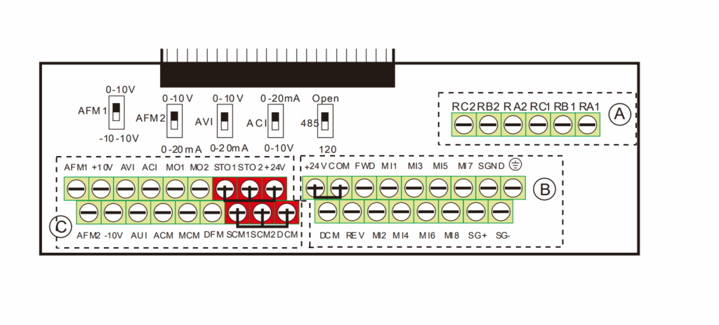
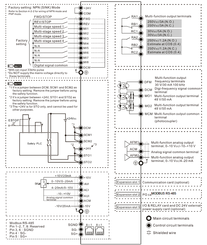
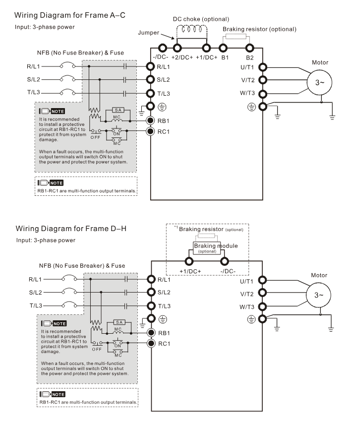
Wiring Details
Below image show terminal details:
Faults & Alarms
Search from below list for C2000 drive faults & alarms:
| Fault Code | Cause & Solution |
|---|---|
| oL Over load | Meaning: The AC motor drive detects excessive drive output current. When the load is higher than the protection level and exceeds allowable time, the oL protection activates. Overload capacity: – Normal duty: Sustains for one minute when the drive outputs 120% of the drive’s rated output current. Sustains for three seconds when the drive outputs 150% of the drive’s rated output current. – Heavy duty: Sustains for one minute when the drive outputs 150% of the drive’s rated output current. Sustains for three seconds when the drive outputs 200% of the drive’s rated output current. Cause & Solution: 1. The load is too large – Reduce the load Accel./Decel. time or the working cycle are too short – Increase the setting value for Pr.01-12–01-19 (accel./decel. time) 2. V/F voltage is too high – Adjust the settings for Pr.01-01–01-08 (V/F curve), especially the setting value for the mid-point voltage (if the mid-point voltage is set too low, the load capacity decreases at low speed). – Refer to the V/F curve selection of Pr.01-43. 3. The capacity of the drive is too small – Replace the drive with a larger capacity model. 4. Overload during low-speed operation – Reduce the load during low-speed operation. – Increase the drive capacity. – Decrease the carrier frequency of Pr.00-17. 5. Torque compensation is too large – Adjust the torque compensation (refer to Pr.07-26 Torque Compensation Gain) until the output current reduces and the motor does not stall. 6. Check if the setting for stall prevention is correct. – Set the stall prevention to the proper value. 7. Output phase loss – Check the status of three-phase motor. – Check if the cable is broken or the screws are loose. 8. Improper parameter settings for the speed tracking function (including restart after momentary power loss and restart after fault) Correct the parameter settings for speed tracking. – 1. Start the speed tracking function. – 2. Adjust the maximum current for Pr.07-09 speed tracking |
| uC Under current | Meaning: Low current. Cause & Solution: 1. Broken motor cable – Exclude the connection issue of the motor and its load. 2. Improper setting for the low current protection – Set the proper settings for Pr.06-71, Pr.06-72 and Pr.06-73. 3. Low load Check the loading status. – Make sure the loading matches the motor capacity. 4. Warning setting parameter: Pr.06-73 – 0: No function – 1: Fault and coast to stop – 2: Fault and ramp to stop by the 2 nd deceleration time – 3: Warn and continue operation 5. Reset method: – Auto “Warning” occurs when Pr.06-73=3. The “Warning” automatically clears when the output current is larger than (Pr.06-71+0.1 A). – Manual “Error” occurs when Pr.06-73=1 and 2. You must reset manually. |
| occ IGBT short circuit between upper bridge and lower bridge | Cause: IGBT short circuit between upper bridge and lower bridge- Short-circuit is detected between upper bridge and lower bridge of the IGBT module. Soultion: 1. Short-circuit detecting circuit fault. 2. There is an hardware issue in drive. Need to repair or replace drive. |
| uC Under current | Meaning: Low current detection. Fault treatment parameter Pr.06-73 – 0: No function – 1: Fault and coast to stop – 2: Fault and ramp to stop by the 2nd deceleration time – 3: Warn and continue operation Cause & Solution: 1. Motor cable disconnection – Troubleshoot the connection between the motor and the load. 2. Improper setting of low-current protection – Reset Pr.06-71, Pr.06-72 and Pr.06-73 to proper settings. 3. The load is too low – Check the load status. – Check if the motor capacity matches the load. |
| EF External fault | Meaning: External fault. This is programmable fault, comes when drive received external signal for external fault. – When the drive decelerates based on the setting of Pr.07-20, the EF fault displays on the keypad. Fault treatment parameter Pr.07-20 – 0: Coast to stop – 1: Stop by the 1 st deceleration time – 2: Stop by the 2 nd deceleration time – 3: Stop by the 3 rd deceleration time – 4: Stop by the 4 th deceleration time – 5: System deceleration – 6: Automatic deceleration (Pr.01-46) Cause & Solution: 1. External fault – Press RESET key after the fault is cleared. |
| bb External base block | Meaning: When the contact of MIx=bb is ON, the output stops immediately and displays bb on the keypad. The motor is in free running. Cause & Solution: 1. When MIx=bb activates – Verify if the system is back to normal condition, and then press “RESET” key to go back to the default. |
| bF Brake transistor fault | Cause: The brake transistor of the motor drive is abnormal. (for the models with built-in brake transistor). Soultion: 1. Hardware fault – 1. Press “RESET” key to go back to the default. If bF still occurs, then there is an hardware issue in drive need to repair or replace drive. – 2. Power off the motor drive since the internal circuit is abnormal. Use a meter to check if it is short-circuit between B2 to DC-. If short-circuit occurs, then there is an hardware issue in drive need to repair or replace drive. 2. Malfunction caused by interference – Verify wiring/grounding of the main circuit to prevent interference. 3. Using the incorrect brake resistor – Check if the resistance value of the brake resistor matches to the drive. |
| CE1 Communication error 1 | Cause & Solution: (CE1 – RS-485 Modbus illegal function code) 1. Incorrect communication command from upper unit: Check if the communication command is correct. 2. Malfunction caused by interference: Verify the wiring and grounding of the communication circuit. It is recommended to separate the communication circuit from the main circuit, or wire in 90 degree for effective anti-interference performance. 3. Different communication setting from the upper unit: Check if the setting for Pr.09-02 is the same as the setting for the upper unit. 4. Disconnection or bad connection of the cable: Check the cable and replace it if necessary. Reset method: “Warning” occurs when Pr.09-02=0 and the motor drive keeps running. The driven resets automatically when receiving the correct function code. |
| CK1 Communication command error 1 | Cause: Keypad communication data, illegal function code (Keypad auto-detect this error and display it.) Soultion: 1. Incorrect communication command from keypad – Keypad and the motor drive don’t communicate properly. It is recommended to remove the keypad and then reconnect it to the motor drive. 2. Malfunction caused by interference – Verify the wiring and grounding of the communication circuit. It is recommended to separate the communication circuit from the main circuit, or wire in 90 degree for effective anti-interference performance. 3. Different communication setting from keypad – Check if the Baud rate = 19200 bps. Format = RTU8, N, 2. 4. Disconnection or bad connection of the cable – Check the cable and replace it if necessary. |
| CE2 Communication error 2 | Cause & Solution: (CE2 – RS-485 Modbus illegal data address: When the input data address is incorrect) 1. Incorrect communication command from upper unit: Check if the communication command is correct. 2. Malfunction caused by interference: Verify the wiring and grounding of the communication circuit. It is recommended to separate the communication circuit from the main circuit, or wire in 90 degree for effective anti-interference performance. 3. Different communication setting from the upper unit: Check if the setting for Pr.09-02 is the same as the setting for the upper unit. 4. Disconnection or bad connection of the cable: Check the cable and replace it if necessary Reset method: “Warning” occurs when Pr.09-02=0 and the motor drive keeps running. The drive resets automatically when receiving the correct data address. |
| CK2 Communication address error | Cause: Keypad communication data, illegal data address (Keypad auto-detect this error and display it.) Soultion: 1. Incorrect communication command from keypad – Keypad and the motor drive don’t communicate properly. It is recommended to remove the keypad and then reconnect it to the motor drive. 2. Malfunction caused by interference – Verify the wiring and grounding of the communication circuit. It is recommended to separate the communication circuit from the main circuit, or wire in 90 degree for effective anti-interference performance. 3. Different communication setting from keypad – Check if the Baud rate = 19200 bps. Format = RTU8, N, 2. 4. Disconnection or bad connection of the cable – Check the cable and replace it if necessary. |
| CE3 Communication error 3 | Cause & Solution: (CE3 – RS-485 Modbus illegal data value: When the length of communication data is too long) 1. Incorrect communication command from upper unit: Check if the communication command is correct. 2. Malfunction caused by interference: Verify the wiring and grounding of the communication circuit. It is recommended to separate the communication circuit from the main circuit, or wire in 90 degree for effective anti-interference performance. 3. Different communication setting from the upper unit: Check if the setting for Pr.09-02 is the same as the setting for the upper unit. 4. Disconnection or bad connection of the cable: Check the cable and replace it if necessary. Reset method: “Warning” occurs when Pr.09-02=0 and the motor drive keeps running. The drive resets automatically when receiving the correct communication data value. |
| CK3 Communication data error | Cause: Keypad communication data, illegal data value (Keypad auto-detect this error and display it.). Soultion: 1. Incorrect communication command from keypad – Keypad and the motor drive don’t communicate properly. It is recommended to remove the keypad and then reconnect it to the motor drive. 2. Malfunction caused by interference – Verify the wiring and grounding of the communication circuit. It is recommended to separate the communication circuit from the main circuit, or wire in 90 degree for effective anti-interference performance. 3. Different communication setting from keypad – Check if the Baud rate = 19200 bps. Format = RTU8, N, 2. 4. Disconnection or bad connection of the cable – Check the cable and replace it if necessary. |
| CE4 Communication error 4 | Cause & Solution: (CE4 – RS-485 Modbus data is written to read-only address: When the data is written to read-only address.) 1. Incorrect communication command from upper unit: Check if the communication command is correct. 2. Malfunction caused by interference: Verify the wiring and grounding of the communication circuit. It is recommended to separate the communication circuit from the main circuit, or wire in 90 degree for effective anti-interference performance. 3. Different communication setting from the upper unit: Check if the setting for Pr.09-02 is the same as the setting for the upper unit. 4. Disconnection or bad connection of the cable: Check the cable and replace it if is necessary. Reset method: “Warning” occurs when Pr.09-02=0 and the motor drive keeps running. The drive resets automatically when receiving the correct written address of communication data. |
| CK4 Communication slave error | Cause: Keypad communication data is written to read-only address. (Keypad auto-detect this error and display it.). Soultion: 1. Incorrect communication command from keypad – Keypad and the motor drive don’t communicate properly. It is recommended to remove the keypad and then reconnect it to the motor drive. If the problem persists after reconnecting the keypad, pay attention to the motor drive status. For example: Motor drive might reset to default setting during operation or while enabling PLC function. 2. Malfunction caused by interference – Verify the wiring and grounding of the communication circuit. It is recommended to separate the communication circuit from the main circuit, or wire in 90 degree for effective anti-interference performance. 3. Different communication setting from keypad – Check if the Baud rate = 19200 bps. Format = RTU8, N, 2. 4. Disconnection or bad connection of the cable – Check the cable and replace it if is necessary. |
| CE10 Communication error 10 | Cause & Solution: (CE10- RS-485 Modbus transmission time-out: When the communication time exceeds the detection time of Pr.09-03 communication time-out) 1. The upper unit does not transmit the communication command within Pr.09-03 setting time: Check if the upper unit transmits the communication command within the setting time for Pr.09-03. 2. Malfunction caused by interference: Verify the wiring and grounding of the communication circuit. It is recommended to separate the communication circuit from the main circuit, or wire in 90 degree for effective anti-interference performance. 3. Different communication setting from the upper unit: Check if the setting for Pr.09-02 is the same as the setting for the upper unit. 4. Disconnection or bad connection of the cable: Check the cable and replace it if necessary. Reset method: “Warning” occurs when Pr.09-02=0 and the motor drive keeps running. The drive resets automatically when receiving the next communication packet. |
| CK10 Keypad communication time out | Cause: Keypad communication data, transmission time-out (Keypad auto-detect this error and display it.). Soultion: 1. Incorrect communication command from keypad – Keypad and the motor drive don’t communicate properly. It is recommended to remove the keypad and then reconnect it to the motor drive. 2. Malfunction caused by interference – Verify the wiring and grounding of the communication circuit. It is recommended to separate the communication circuit from the main circuit, or wire in 90 degree for effective anti-interference performance. 3. Different communication setting from keypad – Check if the Baud rate = 19200 bps. Format = RTU8, N, 2. 4. Disconnection or bad connection of the cable – Check the cable and replace it if necessary. |
| SE1 Save error 1 | Cause: Keypad COPY error 1: Keypad copy time-out- “SE1” warning occurs when the keypad does not transmit the COPY command to the drive, and does not transmit any data to the drive again in 10 ms at the time you copy the parameters to the drive. – Communication connection error – Keypad error – Control board error Solution 1. The causes of error are mostly communication problems between the keypad and control board. Potential causes include communication signal interference and the unacceptable communication command to the Slave. 2. Check if the error occurs randomly, or only occurs when copying certain parameters (the error displays on the upper right corner of the copy page) |
| SE2 Save error 2 | Keypad COPY error 2: parameter writing error- “SE2” warning occurs when writing the parameters incorrectly at the time you copy parameters to the drive. For example, you copy the new firmware version with added parameters to the drive with old firmware version. Cause: – Add new parameters to the new firmware version. – Malfunction caused by interference. Solution: 1. In this stage, the copied data has been transmitted to the Slave. 2. The Slave compares and processes the copied data, and then saves the data to the Data ROM. During the process, the data error (should be attribution error) may occur, or the data cannot be saved to EEPROM. At this time, the warning occurs. 3. It is suggested to check the status of Data ROM and remove the error causes first. 4. Verify the wiring and grounding of the main circuit, control circuit and the encoder for effective anti-interference performance. |
| oH1 IGBT over-heating warning | The AC motor drive detects IGBT overheating and exceeds the protection level of oH1 warning. (When Pr.06-15 is higher than the IGBT overheating protection level, the drive shows oH1 error without displaying oH1 warning.) – “oH1” warning occurs when IGBT temperature is higher than Pr.06-15 setting value. Cause & Solution: 1. Check if the ambient temperature or temperature inside the cabinet is too high, or if there is obstruction in the ventilation hole of the control cabinet. – Check the ambient temperature. – Regularly inspect the ventilation hole of the control cabinet. – Change the installed place if there are heating objects, such as brake resistors, in the surroundings. – Install/ add cooling fan or air conditioner to lower the temperature inside the cabinet. 2. Check if there is any obstruction on the heat sink or if the fan is running -Remove the obstruction or replace the cooling fan. 3. Insufficient ventilation space – Increase ventilation space of the drive. 4. Check if the drive matches the corresponded loading – Decrease loading. – Decrease the carrier wave. – Replace with a drive with larger capacity. 5. The drive has run 100% or more of the rated output for a long time. – Replace with a drive with larger capacity. |
| oH2 Over-heat key components | Cause: The drive has detected the key components are over heat. Soultion: 1. Check if the ambient temperature or temperature inside the cabinet is too high, or if there is obstruction in the ventilation hole of the control cabinet. – 1. Check the ambient temperature. – 2. Regularly inspect the ventilation hole of the control cabinet. – 3. Change the installed place if there are heating objects, such as braking resistors, in the surroundings. – 4. Install/ add cooling fan or air conditioner to lower the temperature inside the cabinet. 2. Check if there is any obstruction on the heat sink or if the fan is running – Remove the obstruction or replace the cooling fan. 3. Insufficient ventilation space – Increase ventilation space of the drive. 4. Check if the drive matches the corresponded loading – 1. Decrease loading. – 2. Decrease the carrier. – 3. Replace with a drive with larger capacity. 5. The drive has run 100% or more of the rated output for a long time – Replace with a drive with larger capacity. 6. Unstable power – Install reactor(s). 7. The load changes frequently – Reduce the changes of the load. |
| PID PID feedback error | PID feedback loss (warning for analog feedback signal; works only when PID enables). – When the analog input is lower than 4 mA (only detects analog input 4–20 mA) Cause & Solution: 1. Loose or broken PID feedback wiring – Tighten the terminals again. – Replace with a new cable. 2. Feedback device malfunction – Replace with a new feedback device. 3. Hardware error – If the PID error still occurs after checking all the wiring, return to the factory for repair. 4. Warning setting parameter – Pr.08-09 – 0: Warn and continue operation – 1: Fault and ramp to stop – 2: Fault and coast to stop – 3: Warn and operate at last frequency 5. Reset method – Auto “Warning” occurs when Pr.08-09=0 or 3. The “Warning” automatically clears when the feedback signal is larger than 4 mA. – Manual “Error” occurs when Pr.08-09=1 or 2. You must reset manually. |
| AnL ACI analog signal loss | Analog input current loss (including all analog 4–20 mA signals) – When the analog input is lower than 4 mA (only detects analog input 4–20 mA) Cause & Solution: 1. Loose or broken ACI wiring – Tighten the terminals again. – Replace with a new cable. 2. External device error – Replace with a new device. 3. Hardware error – If the AnL error still occurs after checking all the wiring, return to the factory for repair. 4. Warning setting parameter: Pr.03-19 – 0: Disable – 1: Continue operation at the last frequency (warning, keypad displays ANL) – 2: Decelerate to 0 Hz (warning, keypad displays ANL) – 3: Stop immediately and display “ACE” 5. Reset method – Auto “Warning” occurs when Pr.03-19=1 or 2. The “Warning automatically clears when the analog input signal is larger than 4 mA. – Manual “Error” occurs when Pr.03-19=3. You must reset manually. |
| uC Under current | Meaning: Low current. Cause & Solution: 1. Broken motor cable – Exclude the connection issue of the motor and its load. 2. Improper setting for the low current protection – Set the proper settings for Pr.06-71, Pr.06-72 and Pr.06-73. 3. Low load Check the loading status. – Make sure the loading matches the motor capacity. 4. Warning setting parameter: Pr.06-73 – 0: No function – 1: Fault and coast to stop – 2: Fault and ramp to stop by the 2 nd deceleration time – 3: Warn and continue operation 5. Reset method: – Auto “Warning” occurs when Pr.06-73=3. The “Warning” automatically clears when the output current is larger than (Pr.06-71+0.1 A). – Manual “Error” occurs when Pr.06-73=1 and 2. You must reset manually. |
| PGFB PG FBK Warning | Cause: PG feedback error- Motor runs in a reverse direction to the direction of frequency command. Warning setting parameter Pr.10-08=0 0: Warn and operation continue 1: Fault and ramp to stop 2: Fault and coast to stop Soultion: 1. Incorrect encoder parameter setting – Reset encoder parameter (Pr.10-02). 2. Check if the connection of encoder is loss – Wiring again. 3. Broken PG card or PG encoder – Replace with a new PG card or encoder. 4. Malfunction caused by interference – Verify wiring of the control circuit, andwiring/grounding of the main circuit to prevent interference. |
| oSPd Over speed warning | Meaning: Over speed warning. – The encoder feedback speed > Pr.10-10. Cause & Solution: 1. Improper setting for Pr.10-25 FOC bandwidth for speed observer. – Decrease setting value for Pr.10-25. 2. Improper bandwidth setting for ASR speed controller. – Increase the bandwidth setting for ASR speed controller. 3. Incorrect motor parameter setting. – Reset motor parameter and run parameter tuning. 4. Malfunction caused by interference. – Verify the wiring of the control circuit, and the wiring/grounding of the main circuit to prevent interference. 5. Warning setting parameter Pr.10-12=0 – 0: Warn and continue operation 6. Reset method – “Warning” automatically clears when the drive stops 7. Reset condition – “Warning” automatically clears when the drive stops |
| dAvE Deviation Warning | Meaning: Over speed deviation warning. Cause & Solution: 1. Improper parameter setting for the slip error. – Reset proper value for Pr.10-13 and Pr.10-14. 2. Improper setting for ASR parameter and acceleration/ deceleration. – Reset ASR parameters. Set proper accel./ decel. time. 3. Accel./ Decel. time is too short. – Reset proper accel./ decel. time. 4. Motor locked. – Remove the causes of motor locked. 5. Mechanical brake is not released. – Check the action timing of the system. 6. Warning setting parameter Pr.10-15 – Encoder Stall and Slip Error Action =0 0: Warn and continue operation 7. Reset method: – “Warning” automatically clears when the drive stops |
| PHL Phase loss | Meaning: Input phase loss warning. – One of the phases outputs less than Pr.06-47 Cause & Solution: 1. Phase loss of the input power – Verify the wiring of the main circuit. 2. Single phase power input on a three-phase model – Use the model with voltage that matches the power. 3. The power voltage has changed – If the power of main circuit works well, check if the MC of the main circuit is broken. Cycle the power after verifying the power is normal. If PHL still occurs, return to the factory for repair. 4. Loose wiring terminal of input power – Tighten the terminal screws with the torque listed in the user manual. 5. Check if the input cable of three-phase power is broken Make sure the wiring is correct. – Replace the broken part of the cable. 6. Unbalanced three-phase of the input power – Check the status of three-phase power. 7. Warning setting parameter Pr.06-45 – Output Phase Loss Detection Action (OPHL) =0 0: Warn and continue operation |
| ot1 Over-torque 1 | Meaning: Over-torque 1 warning. Cause & Solution: 1. Incorrect parameter setting – Configure the settings for Pr.06-07 and Pr.06-08 again. 2. Mechanical error (e.g. mechanical lock due to over-torque) – Remove the causes of malfunction. 3. The load is too large – Decrease the loading. – Replace with a motor with larger capacity. 4. Accel./ Decel. time and working cycle is too short – Increase the setting values for Pr.01-12–01-19 (accel./ decel. time) 5. V/F voltage is too high – Adjust the V/F curve (Motor 1, Pr.01-01–01-08), especially the setting value for the mid-point voltage (if the mid-point voltage is set too small, the load capacity decreases at low-speed). 6. The motor capacity is too small – Replace with a motor with larger capacity. 7. Overload during low-speed operation – Decrease the loading during low-speed operation. – Increase the motor capacity. 8. The torque compensation is too large – Adjust the torque compensation value (Pr.07-26 torque compensation gain) until the output current decreases and the motor does not stall. 9. Improper parameter settings for the speed tracking function (including restart after momentary power loss and restart after fault) – Correct the parameter settings for speed tracking. – Start the speed tracking function. – Adjust the maximum current for Pr.07-09 speed tracking. 10. Incorrect parameter setting – Configure the settings for Pr.06-07 and Pr.06-08 again. 11. Warning setting parameter Pr.06-06 Over-torque Detection Selection (Motor 1) =1 or 3 – 0: No function – 1: Continue operation after over-torque detection during constant speed operation – 2: Stop after over-torque detection during constant speed operation – 3: Continue operation after over-torque detection during RUN – 4: Stop after over-torque detection during RUN |
| ot2 Over-torque | Meaning: Over-torque 2 warning. Cause & Solution: 1. Incorrect parameter setting – Configure the settings for Pr.06-10 and Pr.06-11 2. Mechanical error (e.g. mechanical lock due to over-torque) – Remove the causes of malfunction. 3. The load is too large – Decrease the loading. – Replace with a motor with larger capacity. 4. Accel./ Decel. time and working cycle is too short – Increase the setting values for Pr.01-12–01-19 (accel./ decel. time) 5. V/F voltage is too high – Adjust the V/F curve (Motor 2, Pr.01-35–01-42), especially the setting value for the mid-point voltage (if the mid-point voltage is set too small, the load capacity decreases at low-speed). 6. Warning setting parameter Pr.06-09 Over-torque Detection Selection (Motor 2) =1 or 3 – 0: No function – 1: Continue operation after over-torque detection during constant speed operation – 2: Stop after over-torque detection during constant speed operation – 3: Continue operation after over-torque detection during RUN – 4: Stop after over-torque detection during RUN |
| oH3 Motor over-heating PTC | Meaning: Motor overheating warning- The AC motor drive detects the temperature inside the motor is too high. – Pr.03-00=6 (PTC), PTC input level > Pr.06-30 PTC level (default=50%). Cause & Solution: 1. Motor locked – Clear the motor lock status. 2. The load is too large Decrease the loading. – Replace with a motor with larger capacity. 3. Ambien temperature is too high – Change the installed place if there are heating devices in the surroundings. Install/ add cooling fan or air conditioner to lower the ambient temperature. 4. Motor cooling system error – Check the cooling system to make it work normally. 5. Motor fan error – Replace the fan. 6. Operates at low-speed too long – Decrease low-speed operation time. Change to dedicated motor for the drive. Increase the motor capacity. 7. Accel./ Decel. time and working cycle is too short – Increase setting values for Pr.01-12–01-19 (accel./ decel. time). 8. V/F voltage is too high – Adjust settings for Pr.01-01–01-08 (V/F curve), especially the setting value for the mid-point voltage (if the mid-point voltage is set too small, the load capacity decreases at low-speed). 9. Check if the motor rated current matches the motor nameplate – Configure the correct rated current value of the motor again. 10. Warning setting parameter Error treatment: Pr.06-29 – 0: Warn and continue operation – 1: Fault and ramp to stop – 2: Fault and coast to stop – 3: No warning – When Pr.06-29=0 and when the temperature is ≦ Pr.06-30 level, the oH3 warning automatically clears. – When Pr.06-29=0 (“Warning”), it automatically resets. 11. Reset method: When Pr.06-29=0, oH3 displays as “Warning”. When the temperature is ≦ Pr.06-30 level, the oH3 warning automatically clears. 12. Check if the PTC is properly set and wired – Check the connection between PTC thermistor and the heat protection. 13. Check if the setting for stall prevention is correct – Set the stall prevention to the proper value. 14. Unbalanced three-phase impedance of the motor – Replace the motor. 15. Harmonics is too high – Use remedies to reduce harmonics. |
| oH3 Motor over-heating PT100 | Meaning: Motor overheating warning- The AC motor drive detects the temperature inside the motor is too high. – Pr.03-00=11 (PT100), PT100 input level > Pr.06-57 (default=7 V). Cause & Solution: 1. Motor locked – Clear the motor lock status. 2. The load is too large – Decrease loading. – Replace with a motor with larger capacity. 3. Ambien temperature is too high – Change the installed place if there are heating devices in the surroundings. – Install/ add cooling fan or air conditioner to lower the ambient temperature. 4. Motor cooling system error – Check the cooling system to make it work normally. 5. Motor fan error – Replace the fan. 6. Operates at low-speed too long – Decrease low-speed operation time. – Change to dedicated motor for the drive. – Increase the motor capacity. 7. Check if the PT100 is properly set and wired – Check the connection between PT100 thermistor and the heat protection. 8.Check if the motor rated current matches the motor nameplate – Configure the correct rated current value of the motor again. 9. Accel./ Decel. time and working cycle is too short – Increase the setting values for Pr.01-12–01-19 (accel./ decel. time). 10. Warning setting parameter Error treatment: Pr.06-29 – 0: Warn and continue operation – 1: Fault and ramp to stop – 2: Fault and coast to stop – 3: No warning – When Pr.06-29=0 and when the temperature is < Pr.06-56 level, the oH3 warning automatically clears. – If the temperature is between Pr.06-56 and Pr.06-57, the frequency outputs according to the operating frequency setting for Pr.06-58. 11. Reset method When Pr.06-29=0, oH3 displays as “Warning”. When the temperature is < Pr.06-56 level, the oH3 warning automatically clears. |
| oSL Over slip warning | Meaning: Over slip warning- By using the maximum slip (Pr.10-29) as the base, when the drive outputs at constant speed, and the F>H or F Cause & Solution: 1. Check if the motor parameter is correct – Check the motor parameter. 2. The load is too large – Decrease the loading. 3. Check if the settings for Pr.07-29, Pr.07-30 and Pr.10-29 are properly set – Check the parameter settings for oSL protection. 4. Warning setting parameter Pr.07-31=0 Warning – 0: Warn and continue operation – 1: Fault and ramp to stop – 2: Fault and coast to stop – 3: No warning 5. Reset method: When Pr.07-31=0 and when the drive outputs at constant speed, and F>H or F |
| tUn Auto tuning | Meaning: Parameter auto-tuning is processing. When running auto-tuning, the keypad displays “tUn”. – When running Pr.05-00 motor parameter auto-tuning, the keypad displays “tUn”. Cause & Solution: 1. The motor parameter is running auto-tuning – When the auto-tuning is finished, the warning automatically clears. 2. Reset method: When auto-tuning is finished and no error occurs, the warning automatically clears. |
| oPHL Output phase loss | Meaning: Output phase loss of the drive. This fault also comes when you run drive without motor or one of phase is not connected. Cause & Solution: 1. Unbalanced three-phase impedance of the motor Replace the motor. 2. Check if the wiring is incorrect Check the cable. – Replace the cable. 3. Check if the motor is a single-phase motor – Choose a three-phase motor. 4. Check if the current sensor is broken – Check if the control board cable is loose. If yes, reconnect the cable and run the drive to test. If the error still occurs, return to the factory for repair. – Check if the three-phase current is balanced with a current clamp meter. If the current is balanced and the oPHL error still shows on the display, then need to repair or replace drive. 5. Check if capacity of the drive is larger than the motor – Choose a drive’s capacity matches a motor’s. 6. Warning setting parameter Pr.06-45 – 0: Warn and continue operation – 1: Fault and ramp to stop – 2: Fault and coast to stop – 3: No warning |
| SE3 Copy model error 3 | Meaning– Keypad COPY error 3: copy model error – “SE3” warning occurs when different drive identity codes are found during copying parameters. Cause & Solution: 1. Keypad copy between different power range drives. – It is mainly to prevent parameter copies between different HP/models. |
| CGdn CANopen guarding time-out | Meaning: CANopen guarding time-out 1 – When CANopen Node Guarding detects that one of the slaves does not respond, the CGdn error displays. The upper unit sets the factor and time during configuration. Cause & Solution: 1. The guarding time is too short, or less detection times – Increase the guarding time (Index 100C) and detection times. 2. Malfunction caused by interference – Verify the wiring and grounding of the communication circuit. It is recommended to separate the communication circuit from the main circuit, or wire in 90 degree for effective anti-interference performance. – Make sure the communication circuit is wired in series. – Use CANopen cable or add terminating resistance. |
| CHbn CANopen heartbeat error | Meaning: CANopen heartbeat error- When CANopen Heartbeat detects that one of the slaves does not response, the CHbn error shows. The upper unit sets the confirming time of producer and consumer during configuration. Cause & Solution: 1. The heartbeat time is too short – Increase heartbeat time (Index 1016). 2. Malfunction caused by interference – Verify the wiring and grounding of the communication circuit. It is recommended to separate the communication circuit from the main circuit, or wire in 90 degree for effective anti-interference performance. – Make sure the communication circuit is wired in series. – Use CANopen cable or add terminating resistance. 3. Communication cable is broken or bad connected – Check or replace the communication cable. |
| CbFn CANopen bus off error | Meaning: CANopen BUS off error 1. Hardware – When CANopen card is not installed, the CbFn warning occurs. 2. Software – When the master receives wrong communication package, the CbFn warning occurs. – Too much interference on BUS – The master receives wrong package when the CAN_H and CAN_L communication cables are short, CbFn warning occurs. Cause & Solution: 1. Check if the CANopen card is installed – Make sure the CANopen card is installed. 2. Check if the CANopen speed is correct – Reset CANopen speed (Pr.09-37) 3. Malfunction caused by interference – Verify the wiring and grounding of the communication circuit. It is recommended to separate the communication circuit from the main circuit, or wire in 90 degree for effective anti-interference performance. – Make sure the communication circuit is wired in series. – Use CANopen cable or add terminating resistance. 4. Communication cable is broken or bad connected – Check or replace the communication cable. |
| Cidn CANopen index error | Meaning: CANopen index error- CANopen communication Index error. Cause & Solution: 1. Incorrect setting of CANopen index – Reset CANopen index (Pr.00-02=7) |
| CAdn CANopen station address error | Meaning: CANopen station address error (only supports 1–127) – CANopen station address error. Cause & Solution: 1. Incorrect setting of CANopen station address – Disable CANopen (Pr.09-36=0) – Reset CANopen (Pr.00-02=7) – Reset CANopen station address (Pr.09-36) |
| CFrn CANopen memory error | Meaning: CANopen memory error- When you update the firmware version of the control board, the FRAM internal data does not change, then CFrn warning occurs. Cause & Solution: – CANopen internal memory error 1. Disable CANopen (Pr.09-36=0) 2. Reset CANopen (Pr.00-20=7) 3. Reset CANopen station address (Pr.09-36) |
| CSdn CANopen SDO time-out | Meaning: SDO transmission time-out (only shows on master station)- When the CANopen master transmits a SDO command, and the slave response “times-out”, CSdn warning occurs. Cause & Solution: 1. Slave is not connected – Connect the slave and CANopen BUS. 2. The synchronous cycle is set too short – Increase the synchronous time (Index 1006) 3. Malfunction caused by interference – Verify the wiring and grounding of the communication circuit. It is recommended to separate the communication circuit from the main circuit, or wire in 90 degree for effective anti-interference performance. – Make sure the communication circuit is wired in series. – Use CANopen cable or add terminating resistance. 4. Disconnection or bad connection of the communication cable – Check the status of the cable, or replace the cable Reset method: When the master resends a SDO command and receives the response, the warning automatically clears. |
| CSbn CANopen SDO receives register overflow | Meaning: CANopen SDO receives register overflow- The upper unit sends too much SDO at one time and causes buffer overflow. Cause & Solution: 1. Too much SDO from the upper unit at one time – Check if the master sends too much SDO command. Make sure the master sends the SDO command according to the command format. 2. Reset method: The upper unit sends a reset package to clear the warning. |
| CPtn CANopen format error | Meaning: CANopen protocol format error- The slave detects that communication data from the upper unit cannot be recognized, and then CPtn warning occurs. Cause & Solution: 1. The upper unit sends incorrect communication packet – Make sure the master sends the packet based on CANopen DS301 standard command format. |
| Plra RTC Adjust | Cause: PLC (RTC) is not adjusted. – When using RTC function for PLC program, and PLC detects unreasonable RTC time, PLrA warning displays. Soultion: 1. When using RTC function for PLC program, and the drive is power off over 7 days or KPC-CC01 does not connect to the drive for a long time, the RTC time is different with the internal calculated time when re-connect the keypad to the drive. – 1. Stop the PLC program and restart it. – 2. Adjust the RTC time and cycle the power. 2. KPC-CC01 does not adjust the RTC time – Adjust the RTC time and cycle the power. 3. PLC detects unreasonable RTC time – 1. Stop the PLC program and restart it. – 2. Cycle the power. 4. Replace with a new KPC-CC01 – 1. Stop the PLC program and restart it. – 2. Cycle the power. |
| PLrt Keypad RTC time-out | Cause: PLC (RTC) error. Soultion: 1. KPC-CC01 is not connected to the control board while using the RTC function – Do not remove the KPC-CC01 keypad while using RTC function. |
| PLod PLC opposite defect | Meaning: PLC download error warning- During PLC downloading, the program source code detects incorrect address (e.g. the address exceeds the range), then the PLod warning occurs. Cause & Solution: 1. Incorrect data number is found when downloading the PLC program – Use the correct data number. 2. Reset method: Check if the program is correct and download the program again. If the fault does not exist, the warning automatically clears. |
| PLSv PLC save memory error | Meaning: Data error during PLC operation- The program detects incorrect written address (e.g. the address exceeds the range) during PLC operation, then the PLSv warning occurs. Cause & Solution: 1. An incorrect written address is detected during PLC operation – Make sure the written address is correct and download the program again. 2. Reset method: – Check if the program is correct and download the program again. If the fault does not exist, the warning automatically clears. |
| PLdA Data defect | Meaning: Data error during PLC operation- The program detects incorrect written address when translating the program source code (e.g. the address exceeds the range) during PLC downloading, then PLdA warning occurs. Cause & Solution: 1. During PLC operation, the external Modbus has written/read incorrect data to internal PLC program – Check if the upper unit transmits the correct command 2. Reset method: Check if the program is correct and download the program again. If the fault does not exist, the warning automatically clears. |
| PLFn Function defect | Meaning: PLC download function code error- The program detects incorrect command (unsupported command) during PLC downloading, then PLFn warning occurs. Cause & Solution: 1. Unsupported command has used while downloading the program – Check if the firmware of the drive is the old version 2. Reset method- Check if the program is correct and download the program again. If the fault does not exist, the warning automatically clears. |
| PLor PLC buffer overflow | Meaning: PLC register overflow- When PLC runs the last command and the command exceeds the maximum capacity of the program, then PLor warning occurs. Cause & Solution: 1. The program detects internal source code error during PLC operation – 1. Disable PLC – 2. Reset the PLC program (Pr.00-02=6) – 3. Enable PLC – 4. Re-download the PLC program 2. Reset method: Check if the program is correct and download the program again. If the fault does not exist, the warning automatically clears. |
| PLFF Function defect | Meaning: Function code error during PLC operation- The program detects incorrect command (unsupported command) during PLC operation, then PLFF warning occurs. Cause & Solution: 1. The PLC runs an incorrect command during operation – When starting the PLC function and there is no program in the PLC, the PLFF warning occurs. This is a normal warning, please download the program. 2. Reset method: Check if the program is correct and download the program again. If the fault does not exist, the warning automatically clears. |
| PLSn Checksum error | Meaning: PLC checksum error- PLC checksum error is detected after the drive is powered on, then PLSn warning occurs. Cause & Solution: 1. The program detects checksum error during PLC operation – 1. Disable PLC – 2. Reset the PLC program (Pr.00-02=6) – 3. Enable PLC – 4. Re-download the PLC program 2. Reset method: Check if the program is correct and download the program again. If the fault does not exist, the warning automatically clears. |
| PLEd No end command | Meaning: PLC end command is missing- The “End” command is missing until the last command is executed, the PLEd warning occurs. Cause & Solution: 1. There is no “END” command during PLC operation – 1. Disable PLC – 2. Reset the PLC program (Pr.00-02=6) – 3. Enable PLC – 4. Re-download the PLC program 2. Reset method: Check if the program is correct and download the program again. If the fault does not exist, the warning automatically clears. |
| PLCr PLC MCR error | Meaning: PLC MCR command error- The MC command is detected during PLC operation, but there is no corresponding MCR command, then the PLCr warning occurs. Cause & Solution: 1. The MC command is continuously used for more than 9 times – The MC command cannot be used continuously for 9 times. – Check and reset the program, then re-download the program. 2. Reset method: Check if the program is correct and download the program again. If the fault does not exist, the warning automatically clears. |
| PLdF PLC download fail | Meaning: PLC download failure- PLC download failure due to momentary power loss during the downloading. After the power is ON again, the PLdF warning occurs. Cause & Solution: 1. PLC download is forced to stop, so the written program is incomplete. – Check if there is any error in the program and re-download the PLC program. 2. Reset method: Check if the program is correct and download the program again. If the fault does not exist, the warning automatically clears. |
| PLSF PLC scan time fail | Meaning: PLC scan time exceeds the maximum allowable time- When the PLC scan time exceeds the maximum allowable time (400 ms), the PLSF warning occurs. Cause & Solution: 1. The PLC scan time exceeds the maximum allowable time (400 ms). – Check if the source code is correct and re-download the program. 2. Reset method: Check if the program is correct and download the program again. If the fault does not exist, the warning automatically clears. |
| PCGd CAN/M Guard error | Cause: CANopen Master guarding error. – When CANopen Master Node Guarding detects that one of the Slaves does not response, the PCGd warning will display. Soultion: 1. Slave is not connected or CANopen BUS cable is not connected – Connect the Slave and CANopen BUS 2. Malfunction caused by interference – 1. Verify wiring/grounding of the communication circuit. It is recommended to separate the communication circuit from the main circuit, or wire in 90 degree for effective anti-interference performance. – 2. Make sure the communication circuit is wired in series. – 3. Use CANopen cable or add terminating resistance. 3. Communication cable is broken or bad connected – Check or replace the communication cable. |
| PCbF CAN/M BUS off | Cause: CANopen Master BUS off. – When the CANopen master detects erro r packets more than 255 during the BUS off detection, or when the CANopen card is not installed, the PCbF warning displays. – If the BUS cable is not connected, the drive will notreceive issues packet, and the PCbF warning will not display. Soultion: 1. Malfunction caused by interference – 1. Verify wiring/grounding of the communication circuit. It is recommended to separate the communication circuit from the main circuit, or wire in 90 degree for effective anti-interference performance. – 2. Make sure the communication circuit is wired in series. – 3. Use CANopen cable or add terminating resistance. 2. Communication cable is broken or bad connected – Check or replace the communication cable. |
| PCnL CAN/M node lack | Cause: CANopen Master node error. – When the CANopen master configures different setting nodes from the actual nodes, the PCnL warning displays. Soultion: 1. The configured node quantity is different from the actual nodes – Connect BUS to the original slave, orchange the configured node numbers to meet the actual node quantity 2. Communication cable is broken or bad connected – Check or replace the communication cable. |
| PCCt CAN/M cycle time-out | Cause: CANopen Master cycle time-out. – When the transmitted packet from CANopen master exceeds the maximum allowable quantity in a certain time, the PCCt warning displays. Soultion: 1. When the transmitted packet from CANopen master exceeds the maximum allowable quantity in a certain time – Increase the time setting of D1090 synchronization cycle 2. Reset method: The warning automatically clears when changing the configuration and re-executing the program. |
| PCSF CAN/M SDO over | Cause: CANopen Master SDO overflow – When the CANopen master transmits too mu ch SDO that causes buffer overflow, the PCSF warning displays Soultion: 1. Internal PLC transmits too much SDO at once – The PLC program needs to confirm receiving the SDO feedback data before sending another SDO command. 2. Reset method: Cycle the power, or stop the PLC and run the PLC again. |
| PCSd CAN/M SDO time-out | Cause: CANopen Master SDO time-out – When the CANopen master sends a SDO command, and the BUS is too busy to transmit the command, PCSd warning displays. Soultion: 1. When the CANopen master transmits a SDO command, and does not receive feedback from the Slave within 1 sec. – Check if the Slave responds within 1 second. 2. Reset method: The warning automatically clears when the SDO transmits normally. |
| PCAd CAN/M address error | Cause: CANopen Master station address error – When the CANopen master detects an inco rrect or repeated station address from the Slave, the PCAd warning displays. Soultion: 1. When the CANopen master detects an incorrect or repeated station address from the Slave – Set the correct slave station address. 2. Reset method: The warning automatically clears when reset the station address and run the program again. |
| PCTo CAN/M time-out | Cause: When the drive receives an incorrect packet, it means that there is interference or the command from the upper unit does not meet the CANopen command format. Soultion: 1. Malfunction caused by interference – 1. Verify wiring/grounding of the communication circuit. It is recommended to separate the communication circuit from the main circuit, or wire in 90 degree for effective anti-interference performance. – 2. Make sure the communication circuit is wired in series. – 3. Use CANopen cable or add terminating resistance. 2. Reset method: The warning automatically clears after receives another normal packet. |
| ECid ExCom ID fail | Meaning: – Duplicate MAC ID error – Node address setting error Cause & Solution: 1. The setting address exceeds the range (0–63) – Check the address setting of the communication card (Pr.09-70) 2. The speed setting exceeds the range – Standard: 0–2; non-standard: 0–7 3. The address is duplicated with other nodes on the – BUS Reset the address |
| ECLv ExCom power loss | Meaning: Low voltage of the communication card- The 5V power that the drive provides to the communication card is too low. Cause & Solution: 1. The 5V power that the drive provides to the communication card is too low 2. The card is loose. – Make sure the communication card is well inserted |
| ECtt ExCom test mode | Meaning: The communication card is in the test mode- The communication card is in the test mode. Cause & Solution: 1. Communication command error. – Cycle the power 2. Reset method – Cycle the power and enter the normal mode |
| ECbF ExCom Bus off | Meaning: The communication card detects too many errors in the BUS, then enters the BUS-OFF status and stop communicating. – When the drive detects BUS-off (for DeviceNet) Cause & Solution: 1. Poor connection of the cable – Re-connect the cable 2. Bad quality of the cable – Replace the cable |
| ECnP ExCom no power | Meaning: There is no power supply of the DeviceNet- When there is no power supply of the DeviceNet. Cause & Solution: 1. The drive detects that DeviceNet has no power – Check if the cable and power is normal. 2. Reset method – Cycle the power. |
| ECFF ExCom factory defect | Meaning: Factory default setting error. Cause & Solution: 1. Factory default setting error – Use DCISoft to reset to the default value. 2. Reset method – Cycle the power. |
| ECiF ExCom inner error | Meaning: Serious internal error- Internal memory saving error. Cause & Solution: 1. Noise interference – Verify the wiring of the control circuit, and the wiring/grounding of the main circuit to prevent interference. – Cycle the power. 2. The memory is broken – Reset to the default value and check if the error still exists. – If yes, replace the communication card. |
| ECio ExCom IO Net break | Cause: IO connection break off. – IO connection between the communication card and the master is broken off Soultion: 1. The cable is loose – Re-install the cable 2. Incorrect parameter setting for master communication – Check the setting for master communication parameter |
| ECPP ExCom Parameter data error | Meaning: Profibus parameter data error. Cause & Solution: 1. Incorrect GSD file – Get the correct GSD file from the software. |
| ECPi ExCom configuration data error | Meaning: Profibus configuration data error. Cause & Solution: 1. Incorrect GSD file – Get the correct GSD file from the software |
| ECEF Ethernet link fail | Meaning: The Ethernet cable is not connected. Cause & Solution: 1. The Ethernet cable is loose – Re-connect the cable 2. Bad quality of the Ethernet cable – Replace the cable |
| ECto Communication time-out | Meaning: Communication time-out for the communication card and the upper unit. Cause & Solution: 1. Communication card is not connected with the upper unit – Check if the connection of the communication cable is correct 2. Communication error of the upper unit – Check if the communication of the upper unit is normal 3. Reset condition CMC-EC01: auto-resets when the communication with the upper unit is back to normal |
| ECCS Checksum error | Meaning: Checksum error for the communication card and the drive. Cause & Solution: 1. Noise interference – Verify the wiring of the control circuit, and the wiring/grounding of the main circuit to prevent interference. |
| ECrF Return defect | Meaning: Communication card returns to the default setting- Communication card returns to the default setting. Cause & Solution: 1. Communication card is returning to default setting – No actions required. |
| ECo0 Modbus TCP over | Meaning: Modbus TCP exceeds the maximum communication value. Cause & Solution: 1. The Master communication value exceeds the allowable number of the communication cards – Decrease the Master communication value 2. Connection occupied due to not disconnecting the Modbus TPC while the upper unit is connected without communicating. – Revise the program of the upper unit to disconnect the connection while the communication is not used for a long time. 3. A new Modbus TCP connection is built whenever the upper unit is connected to the communication card, which causes connection occupied. – Revise the program of the upper unit to use the same Modbus TCP connection when connecting to the same communication card. |
| ECo1 EtherNet/IP over | Meaning: Ethernet/IP exceeds the maximum communication value. Cause & Solution: 1. The Master communication value exceeds the allowable number of the communication cards – Decrease the Master communication value 2. Connection occupied due to not disconnecting the Modbus TPC while the upper unit is connected without communicating. – Revise the program of the upper unit to disconnect the connection while the communication is not used for a long time. 3. A new Modbus TCP connection is built whenever the upper unit is connected to the communication card, which causes connection occupied. – Revise the program of the upper unit to use the same Modbus TCP connection when connecting to the same communication card. |
| ECiP IP fail | Meaning: IP setting error. Cause & Solution: 1. IP conflict – Reset IP 2. DHCP IP configuration error – Contact MIS to check if DHCP Server works normally |
| EC3F Mail fail | Meaning– Mail warning: Alarm mail is sent when the condition that the alarm set for the communication card was met. – When the condition that the alarm set for the communication card was met. Cause & Solution: 1. Communication card establishes alarm conditions – No actions required |
| ECbY ExCom busy | Meaning– Communication card busy: too many packets are received. Cause & Solution: 1. Too many communication packets for the communication card to process – Decrease communication packets |
| ECCb ExCom card break | Meaning: Communication card break off warning. Cause & Solution: 1. Communication card is loose – Re-install the communication card |
| CPLP Copy PLC: password error | Meaning: Copy PLC password error. When KPC-CC01 is processing PLC copy and the PLC password is incorrect, the CPLP warning shows. – PLC password is incorrect. Cause & Solution: 1. PLC password is incorrect – Reset and enter the correct PLC password |
| CPL0 Copy PLC: Read mode error | Meaning: Copy PLC read mode error- Incorrect process when copying the PLC read mode. Cause & Solution: 1. Using incorrect process to copy the PLC read mode – Cycle the power and copy the PLC read mode again |
| CPL1 Copy PLC: Write mode | Meaning: Copy PLC write mode error- Incorrect process when copying the PLC write mode. Cause & Solution: 1. Using incorrect process to copy the PLC write mode – Cycle the power and copy the PLC write mode again |
| CPLv Copy PLC: version error | Meaning: Copy PLC version error- When non-C2000 built-in PLC is copied to C2000 drive, the CPLv warning shows Cause & Solution: 1. Non-C2000 PLC program is copied to C2000 – Check if the copied PLC program is for C2000. – Use the correct C2000 PLC program. |
| CPLS Copy PLC: size error | Meaning: Copy PLC capacity error. Cause & Solution: 1. The PLC copied to C2000 exceeds the allowable capacity – Check if the copied PLC program is for C2000. – Use C2000 PLC program with correct capacity |
| CPLF Copy PLC: PLC function | Meaning: KPC-CC01 Copy PLC function should be executed when PLC is off. Cause & Solution: 1. PLC function is enabled when KPC-CC01 is running copy PLC – Disable PLC function first, then run the PLC copy function again |
| CPLt Copy PLC: time-out | Cause & Solution: 1. KPC-CC01 is removed while copying the PLC program – The KPC-CC01 cannot be removed during the PLC copy process |
| ictn InrCOM time-out | Meaning: Internal communication time-out- When Pr.09-31= (-1) – (-10) (no -9) and the internal communication between Master and Slave is abnormal, the ictn warning occurs. Cause & Solution: 1. Malfunction caused by interference – Verify the wiring and grounding of the communication circuit. It is recommended to separate the communication circuit from the main circuit, or wire in 90 degree for effective anti-interference performance. 2. Different communication setting from the upper unit – Check if the setting for Pr.09-02 is the same as the setting for the upper unit 3. Disconnection or bad connection of the cable – Check the cable and replace it if necessary. |
| SpdR Estimated speed reverse | Cause: Estimated speed is in a reverse direction with motor actual running direction. Soultion: 1. The motor runs in reverse direction at start – Check if the motor is hold when started, or start the motor with speed source. 2. The difference between motor parameter measured Rr and Rs value is too large – Normally the Rr value of IM is Rs*0.7. If there is much difference of the measured value (e.g. Rr=Rs*0.3), proceed the motor parameter auto-tuning again. 3. Insufficient output torque is dragged to the reverse direction by the load. – Increase the current limit of Pr.06-12, so as to increase the output torque. 4. Warning setting parameter Pr.10-08 – 0: Warn and keep operation – 1: Fault and coast to stop – 2: Fault and ramp to stop |
| dEb Deceleration energy backup error | Cause: Deceleration energy backup. Solution: 1. Instantaneous power off or low voltage and unstable/ sudden heavy load of the power that cause the voltage drop – Check the power consumption 2. Unexpected power off -Check the power consumption |
| INDX Index Pulse Fail | Cause: 1. The Z position difference is bigger than 2 and occurs 2 times. Besides, more than 20 Z position differences bigger than 2 occur in 1 second, 2. The two Zindex position differences > 10 degree mechanical angle. The two situations mentioned above cause Index Pulse Fail. Soultion: 1. Zindex may be affected by noise – Verify if the wiring of the control circuit, the wiring of the main circuit and the grounding wiring are compatible to the noise immunity |
| nHoY Not Home Yet | Cause: The motor drive receives an absolute motion command before homing is completed. Soultion: 1. Error on the time sequence of system control. – Verify if anything wrong on the time sequence. 2. Speed of homing is too slow – Verify if the frequency setting of homing is too slow which causes error on the control time sequence of the upper unit. |
| HPL HW POS Limit | Cause: When under FOCPG mode, the positive running limit (hardware limit switch) of the MI terminals is activated. When under IMFOCPG/PMFOCPG mode, the motor drive reaches positive running limit. Soultion: 1. Error occurs on hardware limit switch – 1. Verify if the switch of hardware limit works properly. – 2. Verify if the switch of hardware limit is installed at the right position. – 3. Verify if the corresponding MI terminals of the positive limit switch is at the right status such as Normal Open and Normal Close. 2. Overshoot – 1. Verify if the Acceleration/ Deceleration time of the motor drive is right. – 2. Verify if the frequency command of the motor drive is right. 3. Select the wrong homing method – Verify if the mechanical parts and homing method co-work properly. |
| HnL HW NEG Limit | Cause: When under FOCPG mode, the negative running limit (hardware limit switch) of the MI terminals is activated. – When under IMFOCPG/PMFOCPG mode, the motor drive reaches negative running limit. Soultion: 1. Error occurs on hardware limit switch – 1. Verify if the switch of hardware limit works properly. – 2. Verify if the switch of hardware limit is installed at the right position. – 3. Verify if the corresponding MI terminals of the positive limit switch is at the right status such as Normal Open and Normal Close. 2. Overshoot – 1. Verify if the acceleration/ deceleration time of the motor drive is right. – 2. Verify if the frequency command of the motor drive is right 3. Select the wrong homing method – Verify if the mechanical parts and homing method co-work properly. |
| SPL SW POS Limit | Cause: When under FOCPG mode, the feedback position of the motor is higher than or equal to the software positive limit set by the parameters. Soultion: 1. Error occurs on software limit switch – Verify if the setting of software limit switch at Pr.11-56 and Pr.11-57 is correct. 2. Overshoot – 1. Verify if the acceleration/ deceleration time of the motor drive is correct. – 2. Verify if the frequency command of the motor drive is correct. |
| SnL SW NEG Limit | Cause: When under FOCPG mode, the feedback position of the motor is lower than or equal to the negative limit set by the parameters. Soultion: 1. Error occurs on software limit switch – Verify if the setting of software limit switch at Pr.11-58 and Pr.11-59 is correct. 2. Overshoot – 1. Verify if the acceleration/ deceleration time of the motor drive is correct. – 2. Verify if the frequency command of the motor drive is correct |
| PoF Posn Overflow | Cause: When the position record is bigger than the setting range at Pr.11-75. – Verify if the current position is over the setting range at Pr.11-75. Soultion: 1. Homing process incomplete – Verify if the homing process is completed. 2. Position record is bigger than the setting range at Pr.11-75 – Verify if the current position is over the upper and lower limit of Pr.11-75. |
| HPF Home Proc. Fault | Cause: Unusual signal occurs during the homing process. Soultion: 1. Unusual external signal is enabled – Verify if there’s any error or signal is enabled and then interrupts the homing process. 2. Press the STOP button during the homing process – Verify if anything wrong at control sequence. |
| oPE Over Pos Err Lim | Cause: This warning code occurs: 1. When the positioning error of a position controller is bigger than the Pr.11-51 2. And when Pr.11-54: Treatment to the large position control error is set as 0: Warn and continue operation. Soultion: 1. Acceleration/ Deceleration time error. – Verify if the acceleration time and the deceleration time is correct. 2. Setting value of Pr.11-51 may be too small. – Verify if the setting value of Pr.11-51 is too small. 3. The position control may not be working properly. – 1. Verify if the position control works properly. – 2. Verify if the settings of APR bandwidth control and the gain value for the APR feed forward are correct. 4. The setting of command curve at the upper unit during the whole pulse positioning process may not be right. – If you set Pr.11-40 =1 (Input from external pulse) or set MI=90 (Position command source switch and choose 1: Input from external pulse), you need to verify if the acceleration/ deceleration curve of the pulse given by the upper unit is correct. |
| ocA Over-current during acceleration | Cause: Output current exceeds three times of the rated current during acceleration. – When ocA occurs, the drive closes the gate of the output immediately, the motor runs freely, and the display shows an ocA error. Cause & Solution: 1. Acceleration time is too short – Increase the acceleration time – Increase the acceleration time of S-curve – Set auto-acceleration and auto-deceleration parameter (Pr.01-44) – Set over-current stall prevention function (Pr.06-03) – Replace the drive with a larger capacity model. 2. Short circuit at motor output due to poor insulation wiring – Check the motor cable and remove causes of the short circuits, or replace the cable before turning on the power. 3. Check for possible burnout or aging insulation of the motor – Check the motor insulation value with megger. Replace the motor if the insulation is poor. 4. The load is too large. – Check if the output current during the whole working process exceeds the AC motor drive’s rated current. If yes, replace the AC motor drive with a larger capacity model. 5. Impulsive change of the load – Reduce the load or increase the capacity of AC motor drive. 6. Use special motor or motor with larger capacity than the drive – Check the motor capacity (the rated current on the motor’s nameplate should ≤ the rated current of the drive) 7. Use ON/OFF controller of an electromagnetic contactor at the output (U/V/W) of the drive – Check the action timing of the contactor and make sure it is not turned ON/OFF when the drive outputs the voltage. 8. V/F curve setting error – Adjust the V/F curve setting and frequency/voltage. When the fault occurs, and the frequency voltage is too high, reduce the voltage. 9. Torque compensation is too large – Adjust the torque compensation (refer to Pr.07-26 torque compensation gain) until the output current reduces and the motor does not stall. 10. Malfunction caused by interference – Verify the wiring of the control circuit and the wiring/grounding of the main circuit to prevent interference. 11. The motor starts when in free run Enable the speed tracking during start-up of Pr.07-12. Improper parameter settings for the speed tracking function (including restart after momentary power loss and restart after fault) Correct the parameter settings for speed tracking. – 1. Start the speed tracking function. – 2. Adjust the maximum current for Pr.07-09 speed tracking. 12. Incorrect combination of control mode and used motor – Check the settings for Pr.00-11 control mode: – 1. For IM, Pr.00-11=0, 1, 2, 3, 5 – 2. For PM, Pr.00-11=4, 6, or 7 13 The length of motor cable is too long – Increase the AC motor drive’s capacity. – Install AC reactor(s) on the output side (U/V/W). 14 Hardware failure – The ocA occurs due to the short circuit or ground fault at the output side of the drive. – Check for possible short circuits between terminals with the electric meter: B1 corresponds to U, V and W; DC- corresponds to U, V and W; corresponds to U, V and W. – If short circuit occurs, return to the factory for repair. 15. Check if the setting for stall prevention is correct – Set the stall prevention to the proper value. |
| ocd Over-current during deceleration | Meaning: Output current exceeds three times of the rated current during deceleration. – When ocd occurs, the drive closes the gate of the output immediately, the motor runs freely, and the display shows an ocd error. Cause & Solution: 1. Deceleration time too short – 1. Increase the deceleration time – 2. Increase the deceleration time of S-curve – 3. Set auto-acceleration and auto-deceleration parameter (Pr.01-44) – 4. Set over-current stall prevention function (Pr.06-03) – 5. Replace the drive with a larger capacity model 2. Check if the mechanical brake of the motor activates too early – Check the action timing of the mechanical brake. 3. Short-circuit at motor output due to poor insulation wiring – Check the motor cable and remove causes of the short circuits, or replace the cable before turning on the power. 4. Check for possible burnout or aging insulation of the motor. 5. Check the motor insulation value with megger. – Replace the motor if the insulation is poor. 6. The load is too large – Check if the output current during the whole working process exceeds the AC motor drive’s rated current. – If yes, replace the AC motor drive with a larger capacity model. 7. Impulsive change of the load Reduce the load or increase the capacity of AC motor drive.Use special motor or motor with larger capacity than the drive – Check the motor capacity (the rated current on the motor’s nameplate should ≤ the rated current of the drive) 8. Use ON/OFF controller of an electromagnetic contactor at the output (U/V/W) of the drive – Check the action timing of the contactor and make sure it is not turned ON/OFF when the drive outputs the voltage. 9. V/F curve setting error – Adjust the V/F curve settings and frequency/voltage. When the fault occurs, and the frequency voltage is too high, reduce the voltage. 10. Torque compensation is too large – Adjust the torque compensation (refer to Pr.07-26 torque compensation gain) until the output current reduces and the motor does not stall. 11. Malfunction caused by interference – Verify the wiring of the control circuit and the wiring/grounding of the main circuit to prevent interference. 12. The length of motor cable is too long – Increase the AC motor drive’s capacity – Install AC reactor(s) on the output side (U/V/W) 13. Hardware error – The ocd occurs due to the short circuit or ground fault at the output side of the drive. – Check for possible short circuits between terminals with the electric meter: B1 corresponds to U, V and W; DC- corresponds to U, V and W; corresponds to U, V and W. |
| ocn Over-current during steady operation | Meaning: Output current exceeds three times of the rated current during constant speed. When ocn occurs, the drive closes the gate of the output immediately, the motor runs freely, and the display shows an ocn error. Cause & Solution: 1. Short-circuit at motor output due to poor insulation wiring Check the motor cable and remove causes of the short circuits, or replace the cable before turning on the power. 2. Check for possible shaft lock, burnout or aging insulation of the motor – Troubleshoot the motor shaft lock. – Check the motor insulation value with megger. Replace the motor if the insulation is poor. 3. Impulsive change of the load – Reduce the load or increase the capacity of AC motor drive. 4. Use special motor or motor with larger capacity than the drive – Check motor capacity (the rated current on the motor’s nameplate should ≤ the rated current of the drive) 5. Use ON/OFF controller of an electromagnetic contactor at the output (U/V/W) of the drive – Check the action timing of the contactor and make sure it is not turned ON/OFF when the drive outputs the voltage. 6. V/F curve setting error – Adjust the V/F curve settings and frequency/voltage. When the fault occurs, and the frequency voltage is too high, reduce the voltage. 7. Torque compensation is too large. – Adjust the torque compensation (refer to Pr.07-26 torque compensation gain) until the output current reduces and the motor does not stall. 8. Malfunction caused by interference – Verify the wiring of the control circuit and the wiring/grounding of the main circuit to prevent interference. 9. The length of motor cable is too long – Increase the AC motor drive’s capacity. – Install AC reactor(s) on the output side (U/V/W). 10 Hardware failure – The ocn occurs due to the short circuit or ground fault at the output side of the drive. – Check for possible short circuit between terminals with the electric meter: B1 corresponds to U, V and W; DC- corresponds to U, V, and W; corresponds to U, V, and W. |
| GFF Ground fault | Meaning: When the drive detects grounding short circuit on the output terminals (U/V/W), the drive closes the gate of the output immediately, the motor runs freely, and the display shows a GFF error. Cause & Solution: 1. Motor burnout or aging insulation occurred – Check the motor insulation value with megger. – Replace the motor if the insulation is poor. 2. Short circuit due to broken cable – Troubleshoot the short circuit. – Replace the cable. 3. Larger stray capacitance of the – cable and terminal – If the motor cable length exceeds 100 m, decrease the setting value for the carrier frequency. – Take remedies to reduce stray capacitance. 4. Malfunction caused by interference – Verify the grounding and wiring of the communication circuit. It is recommended to separate the communication circuit from the main circuit, or wire in 90 degree for effective anti-interference performance. 5. Hardware failure – Cycle the power after checking the status of motor, cable and cable length. If GFF still exists, return to the factory for repair. |
| occ IGBT short circuit between upper bridge and lower bridge | Cause: IGBT short circuit between upper bridge and lower bridge- Short-circuit is detected between upper bridge and lower bridge of the IGBT module. Soultion: 1. Short-circuit detecting circuit fault. 2. There is an hardware issue in drive. Need to repair or replace drive. |
| ocS Over-current at stop | Meaning: Over-current or hardware failure in current detection at stop. Cause & Solution: 1. Malfunction caused by interference – Verify the wiring of the control circuit and the wiring/grounding of the main circuit to prevent interference. 2. Hardware failure – Check if other error codes such as cd1–cd3 occur after cycling the power |
| ovA/ouA Over-voltage during acceleration | Meaning: DC bus over-voltage during acceleration. When ovA occurs, the drive closes the gate of the output, the motor runs freely, and the display shows an ovA error. Cause & Solution: 1. Acceleration is too slow (e.g. hen lifting load decreases acceleration time) – Decrease the acceleration time – Use a braking unit or DC bus – Replace the drive with a larger capacity model. 2. The setting for stall prevention level is smaller than no-load current – The setting for the stall prevention level should be larger than no-load current 3. Power voltage is too high – Check if the input voltage is within the rated AC motor drive input voltage range, and check for possible voltage spikes. 4. ON/OFF switch action of phase-in capacitor in the same power system – If the phase-in capacitor or active power supply unit acts in the same power system, the input voltage may surge abnormally in a short time. In this case, install an AC reactor. 5. Regenerative voltage of motor inertia – Use over-voltage stall prevention function (Pr.06-01) – Use auto-acceleration and auto-deceleration setting (Pr.01-44) – Use a braking unit or DC bus 6. Acceleration time is too short – Check if the over-voltage warning occurs after acceleration stops. When the warning occurs, do the following: – 1. Increase the acceleration time – 2. Set Pr.06-01 over-voltage stall prevention – 3. Increase the setting value for Pr.01-25 S-curve acceleration arrival time 2 7. Motor ground fault – The ground short circuit current charges the capacitor in the main circuit through the power. – Check if there is ground fault on the motor cable, wiring box and its internal terminals. – Troubleshoot the ground fault. 8. Incorrect wiring of brake resistor or brake unit – Check the wiring of the brake resistor and braking unit. 9. Malfunction caused by interference – Verify the wiring of the control circuit and the wiring/grounding of the main circuit to prevent interference. |
| ovd/oud Over-voltage during deceleration | Meaning: DC bus over-voltage during deceleration. When ovd occurs, the drive closes the gate of the output immediately, the motor runs freely, and the display shows an ovd error. Cause & Solution: 1. Deceleration time is too short, causing too large regenerative energy of the load – 1. Increase the setting value of Pr.01-13, Pr.01-15, Pr.01-17 and Pr.01-19 (deceleration time) – 2. Connect the brake resistor, braking unit or DC bus on the drive. – 3. Reduce the brake frequency. – 4. Replace the drive with a larger capacity model. – 5. Use S-curve acceleration/deceleration. – 6. Use over-voltage stall prevention (Pr.06-01). – 7. Use auto-acceleration and auto-deceleration (Pr.01-44). – 8. Adjust the braking level (Pr.07-01 or the bolt position of the brake unit). 2. The setting for stall prevention level is smaller than no-load current – The setting for the stall prevention level should be larger than no-load current 3. Power voltage is too high – Check if the input voltage is within the rated AC motor drive input voltage range, and check for possible voltage spikes. 4. ON/OFF switch action of phase-in capacitor in the same power system – If the phase-in capacitor or active power supply unit acts in the same power system, the input voltage may surge abnormally in a short time. In this case, install an AC reactor. 5. Motor ground fault – The ground short circuit current charges the capacitor in the main circuit through the power. – Check if there is ground fault on the motor cable, wiring box and its internal terminals. – Troubleshoot the ground fault. 6. Incorrect wiring of brake resistor or brake unit – Check the wiring of the brake resistor or braking unit. 7. Malfunction caused by interference – Verify the wiring of the control circuit and the wiring/grounding of the main circuit to prevent interference. |
| ovn/oun Over-voltage during constant speed | Meaning: DC bus over-voltage at constant speed. When ovn occurs, the drive closes the gate of the output immediately, the motor runs freely, and the display shows an ovn error. Cause & Solution: 1. Impulsive change of the load – 1. Connect the brake resistor, braking unit or DC bus to the drive. – 2. Reduce the load. – 3. Replace the drive with a larger capacity model. – 4. Adjust the braking level (Pr.07-01 or bolt position of the brake unit). 2. The setting for stall prevention level is smaller than no-load current – The setting for the stall prevention level should be larger than no-load current 3. Power voltage is too high – Check if the input voltage is within the rated AC motor drive input voltage range, and check for possible voltage spikes. 4. ON/OFF switch action of phase-in capacitor in the same power system – If the phase-in capacitor or active power supply unit acts in the same power system, the input voltage may surge abnormally in a short time. In this case, install an AC reactor. 5. Motor ground fault – The ground short circuit current charges the capacitor in the main circuit through the power. – Check if there is ground fault on the motor cable, wiring box and its internal terminals. – Troubleshoot the ground fault. 6. Incorrect wiring of brake resistor or brake unit – Check the wiring of the brake resistor or braking unit. 7. Malfunction caused by interference – Verify the wiring of the control circuit and the wiring/grounding of the main circuit to prevent interference. |
| ovS/ouS Over-voltage at stop | Meaning: Over-voltage at stop, this fault comes when you stop drive. Cause & Solution: 1. Power voltage is too high Check if the input voltage is within the rated AC motor drive input voltage range, and check for possible voltage spikes. 2. ON/OFF switch action of phase-in capacitor in the same power system – If the phase-in capacitor or active power supply unit activates in the same power system, the input voltage may surge abnormally in a short time. In this case, install an AC reactor. 3. Incorrect wiring of brake resistor or brake unit – Check the wiring of the brake resistor or braking unit. 4. Malfunction caused by interference – Verify the wiring of the control circuit and the wiring/grounding of the main circuit to prevent interference. 5. Hardware failure in voltage detection – Check if other error codes such as cd1–cd3 occur after cycling the power. If yes, return to the factory for repair. 6. Motor ground fault – The ground short circuit current charges the capacitor in the main circuit through the power. – Check if there is ground fault on the motor cable, wiring box and its internal terminals. – Troubleshoot the ground fault. |
| LvA/LuA Low-voltage during acceleration | Meaning: DC bus voltage is lower than Pr.06-00 setting value during acceleration. Cause & Solution: 1. Power-off – Improve power supply condition. 2. Power voltage changes – Adjust voltage to the power range of the drive 3. Start up the motor with large capacity – Check the power system. – Increase the capacity of power equipment. 4. The load is too large – Reduce the load. – Increase the drive capacity. – Increase the acceleration time. 5. Check if there is short circuit plate or any DC reactor installed between terminal +1 and +2 – Connect short circuit plate or DC reactor between terminal +1 and +2. |
| Lvd/Lud Low-voltage during deceleration | Meaning: DC bus voltage is lower than Pr.06-00 setting value during deceleration. Cause & Solution: 1. Power-off – Improve power supply condition. 2. Power voltage changes – Adjust voltage to the power range of the drive. 3. Start up the motor with large capacity – Check the power system. – Increase the capacity of power equipment. 4. Sudden load – Reduce the load. – Increase the drive capacity. 5. DC bus – Install DC reactor(s). |
| Lvn/Lun Low-voltage at constant speed | Meaning: DC bus voltage is lower than Pr.06-00 setting value at constant speed. Cause & Solution: 1. Power-off – Improve power supply condition. 2. Power voltage changes – Adjust voltage to the power range of the drive. 3. Start up the motor with large capacity – Check the power system. – Increase the capacity of power equipment. 4. Sudden load – Reduce the load. – Increase the drive capacity. 5. DC bus – Install DC reactor(s). |
| LvS/LuS Low-voltage at stop | Meaning: 1. DC bus voltage is lower than Pr.06-00 setting value at stop 2. Hardware failure in voltage detection Cause & Solution: 1. Power-off – Improve power supply condition. 2. Incorrect drive models – Check if the power specification matches the drive. 3. Power voltage changes – Adjust voltage to the power range of the drive. – Cycle the power after checking the power. If LvS error still exists then need to repair drive. 4. Start up the motor with large capacity – Check the power system. – Increase the capacity of power equipment. 5. DC bus Install DC reactor(s). |
| orP Phase loss protection | Meaning: Phase loss of power input- When DC bus ripple is higher than the protection level, and the output current exceeds 50% of the rated current, the drive starts counting. When the counting value reaches the upper limit, an orP error occurs. Cause & Solution: 1. Phase loss of input power – Correctly install the wiring of the main circuit power. 2. Single phase power input to three-phase model – Choose the model whose power matches the voltage. 3. Power voltage changes – If the main circuit power works normally, verify the main circuit. – Cycle the power after checking the power, if orP error still exists, then need to repair drive. 4. Loose wiring terminal of input power – Tighten the terminal screws according to the torque described in the user manual. 5. The input cable of three-phase power is cut off Wire correctly. – Replace the cut off cable. 6. Input power voltage changes too much – Verify the setting value for Pr.06-50 Time for Input Phase Loss Detection and Pr.06-52 Ripple of Input Phase Loss 7. Unbalanced three-phase of input power – Check the power three-phase status. |
| oH1 IGBT overheating | Meaning: IGBT temperature exceeds the protection level. – When the setting for Pr.06-15 is higher than the oH1 level, oH1 error occurs instead of oH1 warning. An IGBT overheating error occurs, and the drive stops. Cause & Solution: 1. Check if the ambient temperature or temperature inside the control cabinet is too high, or if there is obstruction in the ventilation hole of the control cabinet. – 1. Check ambient temperature. – 2. Regularly inspect the ventilation hole of the control cabinet. – 3. Change the installed place if there are heating objects, such as brake resistors, in the surroundings. – 4. Install/ add cooling fan or air conditioner to lower the temperature inside the cabinet. 2. Check if there is any obstruction on the heat sink or if the fan is running. – Remove the obstruction or replace the cooling fan. – Insufficient ventilation space Increase ventilation space of the drive. 3. Check if the drive matches the corresponding load – 1. Reduce the load – 2. Reduce the carrier wave – 3. Replace the drive with a larger capacity model. 4. The drive has run 100% or more than 100% of the rated output for a long time – Replace the drive with a larger capacity model. |
| oH2 Over-heat key components | Cause: The drive has detected the key components are over heat. Soultion: 1. Check if the ambient temperature or temperature inside the control cabinet is too high, or if there is obstruction in the ventilation hole of the control cabinet. – 1. Check ambient temperature. – 2. Regularly inspect the ventilation hole of the control cabinet. – 3. Change the installed place if there are heating objects, such as braking resistors, in the surroundings. – 4. Install/ add cooling fan or air conditioner to lower the temperature inside the cabinet. 2. Check if there is any obstruction on the heat sink or if the fan is running. – Remove the obstruction or replace the cooling fan. 3. Insufficient ventilation space – Increase ventilation space of the drive. 4. Check if the drive matches the corresponding load – 1. Reduce the load – 2. Reduce the carrier – 3. Replace the drive with a larger capacity model. 5. The drive has run 100% or more than 100% of the rated output for a long time – Replace the drive with a larger capacity model. 6. Unstable power – Install reactor(s) 7. Load changes frequently – Reduce load changes |
| tH1o IGBT temperature detection failure | Meaning: IGBT hardware failure in temperature detection- NTC broken or wiring failure. – When the IGBT temperature is higher than the protection level, and detection time exceeds 100 ms, the tH1o protection activates. Cause & Solution: 1. Hardware failure Wait for 10 minutes, and then cycle the power. 2. Check if tH1o protection still exists then there is an hardware or software issue in drive. Need to repair or replace drive. |
| tH2o Capacitor hardware fault | Cause: Hardware failure in capacitor temperature detection. Soultion: 1. Hardware failure Wait for 10 minutes, and then cycle the power. 2. After this same fault comes then there is an hardware issue in drive need to repair or replace drive. |
| oL Over load | Meaning: The AC motor drive detects excessive drive output current. When the load is higher than the protection level and exceeds allowable time, the oL protection activates. Overload capacity: – Normal duty: Sustains for one minute when the drive outputs 120% of the drive’s rated output current. Sustains for three seconds when the drive outputs 150% of the drive’s rated output current. – Heavy duty: Sustains for one minute when the drive outputs 150% of the drive’s rated output current. Sustains for three seconds when the drive outputs 200% of the drive’s rated output current. Cause & Solution: 1. The load is too large – Reduce the load Accel./Decel. time or the working cycle are too short – Increase the setting value for Pr.01-12–01-19 (accel./decel. time) 2. V/F voltage is too high – Adjust the settings for Pr.01-01–01-08 (V/F curve), especially the setting value for the mid-point voltage (if the mid-point voltage is set too low, the load capacity decreases at low speed). – Refer to the V/F curve selection of Pr.01-43. 3. The capacity of the drive is too small – Replace the drive with a larger capacity model. 4. Overload during low-speed operation – Reduce the load during low-speed operation. – Increase the drive capacity. – Decrease the carrier frequency of Pr.00-17. 5. Torque compensation is too large – Adjust the torque compensation (refer to Pr.07-26 Torque Compensation Gain) until the output current reduces and the motor does not stall. 6. Check if the setting for stall prevention is correct. – Set the stall prevention to the proper value. 7. Output phase loss – Check the status of three-phase motor. – Check if the cable is broken or the screws are loose. 8. Improper parameter settings for the speed tracking function (including restart after momentary power loss and restart after fault) Correct the parameter settings for speed tracking. – 1. Start the speed tracking function. – 2. Adjust the maximum current for Pr.07-09 speed tracking |
| EoL1 Electronics thermal relay 1 protection | Meaning: Electronics thermal relay 1 protection. The drive coasts to stop once it activates. Start counting when the output current > 150% of the motor 1 rated current. – Pr.06-14 (If the output current is larger than 105% of the motor 1 rated current again within 60 sec., the counting time reduces and is less than Pr.06-14). Cause & Solution: 1. The load is too large – Reduce the load. 2. Accel./Decel. time or the working cycle is too short – Increase the setting values for Pr.01-12–01-19 (accel./decel. time) 3. V/F voltage is too high – Adjust the settings for Pr.01-01–01-08 (V/F curve), especially the setting value for the mid-point voltage (if the mid-point voltage is set too low, the load capacity decreases at low speed). 4. Overload during low-speed operation. When using a general motor, even it operates below rated current, an overload may still occur during low-speed operation. – Decrease low-speed operation time. – Replace the drive with a dedicated to VFD model. – Increase the motor capacity. 5. When using VFD dedicated motors, Pr.06-13=0 (electronic thermal relay selection motor 1 = inverter motor) – Pr.06-13=1 electronic thermal relay selection motor 1 = standard motor (motor with fan on the shaft). 6. Incorrect value of electronic thermal relay – Reset to the correct motor rated current. 7. The maximum motor frequency is set too low – Reset to the correct motor rated frequency. 8. One drive to multiple motors – Set Pr.06-13=2 electronic thermal relay selection motor 1= disable, and install thermal relay on each motor. 9. Check if the setting for stall prevention is correct. – Set the stall prevention to the proper value. 10. Torque compensation is too large – Adjust the torque compensation (refer to Pr.07-26 torque compensation gain) until the current reduces and the motor does no stall. 11. Motor fan error Check the status of the fan, or replace the fan. Unbalanced three-phase impedance of the motor – Replace the motor. |
| EoL2 Electronic thermal relay 2 protection | Meaning: Electronic thermal relay 2 protection. The drive coasts to stop once it activates. – Start counting when the output current > 150% of the motor 2 rated current. Cause & Solution: 1. The load is too large – Reduce the load 2. Accel./Decel. time or the working cycle are too short – Increase the setting values for Pr.01-12–01-19 (accel./decel. time) 3. V/F voltage is too high – Adjust the settings for Pr.01-35–01-42 (V/F curve), especially the setting value for the mid-point voltage (if the mid-point voltage is set too low, the load capacity decreases at low speed). 4. Overload during low-speed operation. When using general motor, even it operates below rated current, an overload may still occur during low-speed operation. – Decrease low-speed operation time. – Replace the drive with a dedicated to VFD model. – Increase the motor capacity. 5. Incorrect value of electronic thermal relay – Reset to the correct motor rated current. 6. The maximum motor frequency is set too low – Reset to the correct motor rated frequency. 7. One drive to multiple motors – Set Pr.06-27=2 Electronic thermal relay selection motor 2 = disable, and install thermal relay on each motor. 8. Check if the setting for stall prevention is correct. – Set the stall prevention to the proper value. 9. Torque compensation is too large – Adjust the torque compensation (refer to Pr.07-71 torque compensation gain) until the current reduces and the motor does no stall. 10. Motor fan error – Check the status of the fan, or replace the fan. 11. Unbalanced three-phase impedance of the motor – Replace the motor. |
| oH3 Motor overheating PTC | Meaning: Motor overheating (PTC) (Pr.03-00–Pr.03-01=6 PTC), when PTC input > Pr.06-30, the fault treatment acts according to Pr.06-29. – PTC input value > Pr.06-30 setting (Default = 50%). Fault treatment parameter Pr.06-29 – 0: Warn and continue operation – 1: Fault and ramp to stop – 2: Fault and coast to stop – 3: No warning Cause & Solution: 1. Motor shaft lock – Remove the shaft lock. 2. The load is too large – Reduce the load. – Increase the motor capacity. 3. Ambient temperature is too high – Change the installed place if there are heating devices in the surroundings. – Install/ add cooling fan or air conditioner to lower the ambient temperature. 4. Motor cooling system error – Check the cooling system to make it work normally 5. Operate at low-speed too long. – Decrease low-speed operation time. – Replace the motor with a dedicated to VFD model. – Increase the motor capacity. 6. Accel./Decel. time and working cycle are too short – Increase the setting values for Pr.01-12–01-19 (accel./decel. time) 7. Check if the motor rated current matches that on the motor nameplate. – Reset to the correct motor rated current. 8. Check if the PTC is properly set and wired. – Check the connection between PTC thermistor and the heat protection. 9. Check if the setting for stall prevention is correct. – Set the stall prevention to the proper value. 10. Unbalanced three-phase impedance of the motor – Replace the motor. 11. Harmonics are too high. – Use remedies to reduce harmonics. |
| oH3 Motor overheating PT100 | Meaning: Motor overheating (PT100) (Pr.03-00–Pr.03-01=11 PT100). – When PT100 input > Pr.06-57 (default = 7 V), the fault treatment acts according to Pr.06-29. – PT100 input value > Pr.06-57 setting (default = 7 V) Fault treatment parameter Pr.06-29 – 0: Warn and continue operation – 1: Fault and ramp to stop – 2: Fault and coast to stop – 3: No warning Cause & Solution: 1. Motor shaft lock – Remove the shaft lock. 2. The load is too large – Reduce the load. – Increase the motor capacity. 3. Ambient temperature is too high – Change the installed place if there are heating devices in the surroundings. – Install/ add cooling fan or air conditioner to lower the ambient temperature. 4. Motor cooling system error – Check the cooling system to make it work normally 5. Operate at low-speed too long. – Decrease low-speed operation time. – Replace the motor with a dedicated to VFD model. – Increase the motor capacity. 6. Accel./Decel. time and working cycle are too short – Increase the setting values for Pr.01-12–01-19 (accel./decel. time) 7. Check if the motor rated current matches that on the motor nameplate. – Reset to the correct motor rated current. 8. Check if the PT100 is properly set and wired. – Check connection of PT100 thermistor. 9. Check if the setting for stall prevention is correct. – Set the stall prevention to the proper value. 10. Unbalanced three-phase impedance of the motor – Replace the motor. 11. Harmonics are too high. – Use remedies to reduce harmonics. |
| ot1 Over torque 1 | Meaning: When the output current exceeds the over-torque detection level (Pr.06-07) and exceeds over-torque detection time (Pr.06-08), and when Pr.06-06 or Pr.06-09 is set to 2 or 4, the ot1 error displays. Fault treatment parameter Pr.06-06 – 0: No function – 1: Continue operation after over-torque detection during constant speed operation – 2: Stop after over-torque detection during constant speed operation – 3: Continue operation after over-torque detection during RUN – 4: Stop after over-torque detection during RUN Cause & Solution: 1. Incorrect parameter setting – Configure the settings for Pr.06-07 and Pr.06-08 again. 2. Mechanical failure (e.g. over-torque, mechanical lock) – Remove the causes of malfunction. 3. The load is too large – Reduce the load. – Replace the motor with a larger capacity model. 4. Accel./Decel. time and working cycle are too short – Increase the setting values for Pr.01-12–Pr.01-19 (accel./decel. time) 5. V/F voltage is too high – Adjust the V/F curve (Motor 1, Pr.01-01–01-08), especially the setting value for the mid-point voltage (if the mid-point voltage is set too low, the load capacity decreases at low speed). 6. The motor capacity is too small – Replace the motor with a larger capacity model. 7. Overload during low-speed operation – Decrease low-speed operation time. – Increase the motor capacity. 8. Torque compensation is too large – Adjust the torque compensation (refer to Pr.07-26 torque compensation gain) until the current reduces and the motor does no stall. 9. Improper parameter settings for speed tracking function (including restart after momentary power loss and restart after fault) Correct the parameter settings for speed tracking. – 1. Start the speed tracking function. – 2. Adjust the maximum current for Pr.07-09 speed tracking. |
| ot2 Over torque 2 | Meaning: When the output current exceeds the over-torque detection level (Pr.06-10) and exceeds over-torque detection time (Pr.06-11), and when Pr.06-09 is set to 2 or 4, the ot2 error displays. Fault treatment parameter Pr.06-09 – 0: No function – 1: Continue operation after over-torque detection during constant speed operation – 2: Stop after over-torque detection during constant speed operation – 3: Continue operation after over-torque detection during RUN – 4: Stop after over-torque detection during RUN Cause & Solution: 1. Incorrect parameter setting – Configure the settings for Pr.06-10 and Pr.06-11 again. 2. Mechanical failure (e.g. over-torque, mechanical lock) – Remove the causes of malfunction. 3. The load is too large – Reduce the load. – Replace the motor with a larger capacity model. 4. Accel./Decel. time and working cycle are too short – Increase the setting values for Pr.01-12–Pr.01-19 (accel./decel. time) 5. V/F voltage is too high – Adjust the V/F curve (Motor 1, Pr.01-01–01-08), especially the setting value for the mid-point voltage (if the mid-point voltage is set too low, the load capacity decreases at low speed). 6. The motor capacity is too small – Replace the motor with a larger capacity model. 7. Overload during low-speed operation – Decrease low-speed operation time. – Increase the motor capacity. 8. Torque compensation is too large – Adjust the torque compensation (refer to Pr.07-71 torque compensation gain) until the current reduces and the motor does no stall. 9. Improper parameter settings for speed tracking function (including restart after momentary power loss and restart after fault) Correct the parameter settings for speed tracking. – 1. Start the speed tracking function. – 2. Adjust the maximum current for Pr.07-09 speed tracking. |
| uC Under current | Meaning: Low current detection. Fault treatment parameter Pr.06-73 – 0: No function – 1: Fault and coast to stop – 2: Fault and ramp to stop by the 2nd deceleration time – 3: Warn and continue operation Cause & Solution: 1. Motor cable disconnection – Troubleshoot the connection between the motor and the load. 2. Improper setting of low-current protection – Reset Pr.06-71, Pr.06-72 and Pr.06-73 to proper settings. 3. The load is too low – Check the load status. – Check if the motor capacity matches the load. |
| LiT Limit Error | Cause: This code occurs when the motor drive is running under speed mode (not IMFOCPG/PMFOCPG) and the negative running limit or the positive running limit of the MI terminals is enabled. – When under the speed mode (not FOCPG), negative running limit or positive running limit is enabled. Soultion: 1. The limit ON/OFF switch may be on the wrong position – Install the limit ON/OFF switch to correct position. 2. MI terminal may not be working properly. – Set Pr00-04=16 to verify if the MI terminals work properly. 16: The digital input status (ON / OFF) (i) 3. Deceleration time may be too long, causing the motor cannot stop at limit position – Reduce deceleration time. – Adjust setting value of DC brake current level (Pr.07-01 or the insert position on the brake unit). |
| cF1 EEPROM write error | Cause: Internal EEPROM can not be programmed. Soultion: 1. Press “RESET” key to the factory setting. 2. There is an hardware or software issue in drive. Need to repair or replace drive. |
| cF2 EEPROM read error | Meaning: Internal EEPROM cannot be read- There is an hardware or software issue in drive. Need to repair or replace drive. Cause & Solution: 1. Internal EEPROM cannot be read – Press “RESET” key or reset the parameter to the default setting – Cycle the power – After this same fault comes then hardware issue in drive need to repair or replace drive. |
| cd1 U-phase error | Meaning: U-phase current detection error when power is ON. Cause & Solution: 1. Hardware failure – Cycle the power. 2. Check drive IGBT using multimeter. 3. If fault not reset then there is hardware issue in drive need to repair or replace drive. |
| cd2 V-phase error | Meaning: V-phase current detection error when power is ON. Cause & Solution: 1. Hardware failure – Cycle the power. 2. Check drive IGBT using multimeter. 3. If fault not reset then there is hardware issue in drive need to repair or replace drive. |
| cd3 W-phase error | Meaning: W-phase current detection error when power is ON. Cause & Solution: 1. Hardware failure – Cycle the power. 2. Check drive IGBT using multimeter. 3. If fault not reset then there is hardware issue in drive need to repair or replace drive. |
| Hd0 cc hardware error | Meaning: cc (current clamp) hardware protection error when power is ON. Cause & Solution: 1. Hardware failure – Cycle the power. 2. After this same fault comes then there is an hardware issue in drive need to repair or replace drive. |
| Hd1 oc hardware error | Meaning: oc hardware protection error when power is ON. Cause & Solution: 1. Hardware failure – Cycle the power. 2. After this same fault comes then there is an hardware issue in drive need to repair or replace drive. |
| Hd2 Ov Hardware error | Cause: OV hardware error Soultion: 1. Re-power on to try it. 2. After this same fault comes then there is an hardware issue in drive need to repair or replace drive. |
| Hd3 occ Hardware error | Cause: Occ hardware error Soultion: 1. Reboots the power. 2. After this same fault comes then there is an hardware issue in drive need to repair or replace drive. |
| AUE Auto-tuning error | Meaning: Motor auto-tuning error. Cause & Solution: 1. Press “STOP” key during auto-tuning – Re-execute auto-tuning. 2. Incorrect motor capacity (too large or too small) and parameter setting – Check motor capacity and related parameters. – Set the correct parameters, that is Pr.01-01–Pr.01-02. – Set Pr.01-00 larger than the motor rated frequency. 3. Incorrect motor wiring – Check the wiring. 4. Motor shaft lock – Remove the cause of motor shaft lock. |
| AFE PID loss ACI | Meaning: PID feedback loss (analog feedback signal is only valid when the PID function is enabled). – When the analog input < 4 mA (only detects 4–20 mA analog input. Fault treatment parameter Pr.08-09 – 0: Warn and continue operation – 1: Fault and ramp to stop – 2: Fault and coast to stop – 3: Warn and operate at last frequency Cause & Solution: 1. PID feedback cable is loose or cut off – Tighten the terminal. – Replace the cable with a new one. 2. Feedback device failure – Replace the device with a new one. 3. Hardware failure – Check all the wiring. |
| PGF1 PG feedback error | Cause: The motor runs in a reverse direction to the frequency command direction. Soultion: 1. Incorrect parameter setting of encoder – Reset encoder parameter (Pr. 10-02). 2. Check wiring of the encoder – Re-wire the encoder. 3. PG card or PG encoder failure – Replace PG card or encoder with a new one. 4. Malfunction caused by interference – Verify wiring of the control circuit and wiring/grounding of the main circuit to prevent interference. |
| PGF2 PG feedback loss | Meaning: Pr.10-00 and Pr.10-02 is not set in the PG control mode. When press “RUN” key, PGF2 fault occurs. Cause & Solution: 1. Incorrect setting of encoder parameter – Reset encoder parameters (Pr.10-00 and Pr.10-02) 2. Incorrect selection of the control mode – Choose the correct control mode. |
| PGF3 PG feedback stall | Meaning: Under PG mode, when the motor frequency exceeds the encoder observer stall level (Pr.10-10) and starts to count, the fault time is longer than the detection time of encoder observer stall (Pr.10-11), then PGF3 fault occurs. Fault treatment parameter Pr.10-12 – 0: Warn and continue operation – 1: Fault and ramp to stop – 2: Fault and coast to stop Cause & Solution: 1. Incorrect setting of encoder parameter – Reset encoder parameter (Pr.10-01) 2. Pr. 01-00 is set too small Set proper value for Pr.01-00. 3. Incorrect setting for ASR parameters and accel./decel. time – Reset ASR parameters. – Set correct accel./decel. time. 4. Incorrect setting for PG feedback stall – Reset proper values for Pr.10-10 and Pr. 10-11 |
| PGF4 PG slip error | Meaning: Under PG mode, when the motor frequency exceeds encoder observer slip range (Pr.10-13) and starts to count, the fault time is longer than the detection time of encoder observer slip (Pr.10-14), PGF4 fault occurs. Fault treatment parameter Pr.10-15 – 0: Warn and continue operation – 1: Fault and ramp to stop – 2: Fault and coast to stop Cause & Solution: 1. Incorrect settings for PG feedback parameters – -Reset correct values for Pr.10-13 and Pr.10-14. 2. Incorrect settings for ASR parameters and accel./decel. time – Reset ASR parameters. – Set correct accel./decel time. 3. Incorrect settings of encoder parameters – Reset encoder parameters (Pr.10-01). 4. Accel./Decel. time is too short – Reset proper accel./decel. time. 5. Incorrect settings of torque limit parameters (Pr.06-12,Pr.11-17–20) – Reset proper setting values for Pr.06-12 and Pr.11-17–Pr.11-20. 6. Motor shaft lock – Remove causes of motor shaft lock. 7. Mechanical brake is not released – Check the action timing of the system. |
| ACE ACI loss | Meaning: Analog input loss (including all the 4–20 mA analog signal) – When the analog input is < 4 mA (only detects 4–20 mA analog input) Fault treatment parameter Pr.03-19 – 0: Disable – 1: Continue operation at the last frequency (warning, ANL is displayed on the keypad) – 2: Decelerate to stop (warning, ANL is displayed on the keypad) – 3: Stop immediately and display ACE Cause & Solution: 1. ACI cable is loose or cut off – Tighten the terminal. – Replace the cable with a new one. 2. External device failure – Replace the device with a new one. 3. Hardware failure – Check all the wiring. |
| EF External fault | Meaning: External fault. This is programmable fault, comes when drive received external signal for external fault. – When the drive decelerates based on the setting of Pr.07-20, the EF fault displays on the keypad. Fault treatment parameter Pr.07-20 – 0: Coast to stop – 1: Stop by the 1 st deceleration time – 2: Stop by the 2 nd deceleration time – 3: Stop by the 3 rd deceleration time – 4: Stop by the 4 th deceleration time – 5: System deceleration – 6: Automatic deceleration (Pr.01-46) Cause & Solution: 1. External fault – Press RESET key after the fault is cleared. |
| EF1 Emergency stop | Meaning: When the contact of MIx=EF1 is ON, the output stops immediately and displays EF1 on the keypad. The motor is in free running. Cause & Solution: 1. When MIx=EF1 activates – Verify if the system is back to normal condition, and then press “RESET” key to go back to the default. |
| bb External base block | Meaning: When the contact of MIx=bb is ON, the output stops immediately and displays bb on the keypad. The motor is in free running. Cause & Solution: 1. When MIx=bb activates – Verify if the system is back to normal condition, and then press “RESET” key to go back to the default. |
| Pcod Password is locked | Meaning: Entering the wrong password three consecutive times. – Entering the wrong password three consecutive times. Cause & Solution: Incorrect password input through Pr.00-07 1. Input the correct password after rebooting the motor drive. 2. If you forget the password, do the following steps: Step 1: Input 9999 and press ENTER. Step 2: Repeat step 1. Input 9999 and press ENTER. (You need to finish step 1 and step 2 within 10 seconds. If you don’t finish the two steps in 10 seconds, try again.) 3. The parameter settings return to the default when the “Input 9999” process is finished. |
| ccod SW Code Error | Cause: SW code error. Soultion: There is an hardware or software issue in drive. Need to repair or replace drive. |
| CE1 Illegal command | Meaning: Communication command is illegal. – When the function code is not 03, 06, 10, or 63. Cause & Solution: 1. Incorrect communication command from the upper unit – Check if the communication command is correct. 2. Malfunction caused by interference – Verify the wiring and grounding of the communication circuit. It is recommended to separate the communication circuit from the main circuit, or wire in 90 degree for effective anti-interference performance. 3. Different communication setting from the upper unit – Check if the setting for Pr.09-02 is the same as the setting for the upper unit. 4. Disconnection or bad connection of the cable – Check the cable and replace it if necessary. |
| CE2 Illegal data address | Meaning: Data address is illegal. – When the data address is incorrect. Cause & Solution: 1. Incorrect communication command from the upper unit Check if the communication command is correct. 2. Malfunction caused by interference – Verify the wiring and grounding of the communication circuit. It is recommended to separate the communication circuit from the main circuit, or wire in 90 degree for effective anti-interference performance. 3. Different communication setting from the upper unit – Check if the setting for Pr.09-02 is the same as the setting for the upper unit. 4. Disconnection or bad connection of the cable – Check the cable and replace it if necessary. |
| CE3 Illegal data value | Meaning: Data value is illegal. – When the data length is too long. Cause & Solution: 1. Incorrect communication command from the upper unit Check if the communication command is correct. 2. Malfunction caused by interference – Verify the wiring and grounding of the communication circuit. It is recommended to separate the communication circuit from the main circuit, or wire in 90 degree for effective anti-interference performance. 3. Different communication setting from the upper unit – Check if the setting for Pr.09-02 is the same as the setting for the upper unit. 4. Disconnection or bad connection of the cable – Check the cable and replace it if necessary. |
| CE4 Data is written to read-only address | Meaning: Data is written to read-only address. – When the data is written to read-only address. Cause & Solution: 1. Incorrect communication command from the upper unit Check if the communication command is correct. 2. Malfunction caused by interference – Verify the wiring and grounding of the communication circuit. It is recommended to separate the communication circuit from the main circuit, or wire in 90 degree for effective anti-interference performance. 3. Different communication setting from the upper unit – Check if the setting for Pr.09-02 is the same as the setting for the upper unit. 4. Disconnection or bad connection of the cable – Check the cable and replace it if necessary. |
| CE10 Modbus transmission time-out | Meaning: Modbus transmission time-out occurs. – When the communication time exceeds the detection time for Pr.09-03 communication time-out. Fault treatment parameter Pr.09-02 – 0: Warn and continue operation – 1: Fault and ramp to stop – 2: Fault and coast to stop – 3: No warning, no fault, and continue operation Cause & Solution: 1. The upper unit does not transmit the communication command within Pr.09-03 setting time. – Check if the upper unit transmits the communication command within the setting time for Pr.09-03. 2. Malfunction caused by interference – Verify the wiring and grounding of the communication circuit. It is recommended to separate the communication circuit from the main circuit, or wire in 90 degree for effective anti-interference performance. 3. Different communication setting from the upper unit – Check if the setting for Pr.09-02 is the same as the setting for the upper unit. 4. Disconnection or bad connection of the cable – Check the cable and replace it if necessary. |
| bF Brake transistor fault | Cause: The brake transistor of the motor drive is abnormal. (for the models with built-in brake transistor). Soultion: 1. Hardware fault – 1. Press “RESET” key to go back to the default. If bF still occurs, then there is an hardware issue in drive need to repair or replace drive. – 2. Power off the motor drive since the internal circuit is abnormal. Use a meter to check if it is short-circuit between B2 to DC-. If short-circuit occurs, then there is an hardware issue in drive need to repair or replace drive. 2. Malfunction caused by interference – Verify wiring/grounding of the main circuit to prevent interference. 3. Using the incorrect brake resistor – Check if the resistance value of the brake resistor matches to the drive. |
| ydc Y-connection/ Δ-connection switch error | Meaning: An error occurs when Y-Δ switches. 1. ydc occurs when the confirmation signals of Y-connection and Δ-connection are conducted at the same time. 2. If any of confirmation signals is not conducted within Pr.05-25, ydc occurs. Cause & Solution: 1. The electromagnetic valve operates incorrectly during Y-Δ switch. – Check if the electromagnetic valve works normally. – If not, replace it. 2. Incorrect parameter setting – Check if related parameters are all set up and set correctly. 3. The wiring of Y- Δ switch function is incorrect – Check the wiring. |
| dEb Deceleration energy backup error | Meaning: When Pr.07-13 is not 0, and the power is suddenly off, causing the DC bus voltage lower than the dEb action level, the dEb function acts and the motor ramps to stop. Then dEb displays on the keypad. – When Pr.07-13 is not 0, and the DC bus voltage is lower than the level of dEb. Cause & Solution: 1. Unstable power source or the power is off – Check the power system. 2. There is any other large load operates in the power system – 1. Replace power system with a larger capacity. – 2. Use a different power system from the large load system. |
| oSL Over slip error | Meaning: On the basis of the maximum slip limit set via Pr.10-29, the speed deviation is abnormal. When the motor drive outputs at constant speed, F>H or F Fault treatment parameter Pr.07-31 – 0: Warn and continue operation – 1: Fault and ramp to stop – 2: Fault and coast to stop – 3: No warning Cause & Solution: 1. Any of the motor parameters in parameter group 5 may be incorrect – Check the motor parameters 2. Overload – Decrease the load 3. Any of the setting value of Pr.07-29, 07-30, and 10-29 is improper – Check the setting of oSL protection function related parameters |
| ryF Electric valve switch fault | Cause: Electric valve switch fault when executing Soft Start. Soultion: 1. The input power is abnormal Check if the power is shut down during the drive operation. – Check if the three-phase input power is normal. 2. Malfunction caused by interference – Verify the wiring/grounding of the main circuit to prevent interference. 3. Hardware failure – Cycle the power after checking the power. If ryF fault still occurs, return to the factory for repair. |
| PGF5 Hardware error of PG card | Cause: Hardware error of PG card. 1. The PG card (PG01U/PG02U) can only be used with the permanent magnetic motor. When the power is ON and Pr. 00-04=29 pole section shows 0 or 7 (wiring error or no U/V/W signal input), the PGF5 error will be activated. 2. The drive receives the operationcommand right after the power is ON, meanwhile, the PG card is not ready yet. Soultion: 1. Wiring error or there is no U/V/W signal input – Re-connect the cables correctly 2. Encoder failure – Verify if it is the UVW encoder 3. The setting of encoder parameter is incorrect – Choose the correct setting of Pr. 10-00 4. If the motor selection switch of PG card on the correct position – Check if it is the UVW encoder or Delta encoder 5. PG card selection is incorrect – Install the correct PG card |
| SdRv Reverse direction of the speed feedback | Cause: Rotating direction is different from the commanding direction detected by the sensorless. Soultion: 1. The setting of Pr.10-25 FOC bandwidth of speed observer is improper – Decrease the setting of Pr. 10-25 2. The setting of motor parameter is incorrect – Reset the motor parameter and execute parameter tuning 3. The motor cable is abnormal or broken – Check if the cable is well functioned or replace the cable 4. A reverse force is exerted, or the motor runs in a reverse direction at start – Start speed tracking function (Pr. 07-12) 5. Malfunction caused by interference – Verify the wiring of the control circuit and wiring/grounding of the main circuit to prevent interference. |
| SdOr Over speed rotation feedback | Cause: Over speed rotation detected by sensorless. Soultion: 1. The setting of Pr. 10-25 FOC bandwidth of speed observer is improper – Decrease the setting of Pr. 10-25 2. The setting of ASR bandwidth of speed controller is improper – Increase the bandwidth of ASR speed controller 3. The setting of motor parameter is incorrect – Reset motor parameter and execute parameter tuning 4. Malfunction caused by interference – Verify the wiring of the control circuit and wiring/grounding of the main circuit to prevent interference. |
| SdDe Large deviation of speed feedback | Cause: A large deviation between the rotating speed and the command detected by the sensorless. Soultion: 1. Improper parameter setting for abnormal rotating slip function – Reset proper setting for Pr. 10-13 and Pr. 10-14 2. Improper parameter setting for ASR and acceleration/deceleration – Reset ASR parameters – Set proper acceleration/deceleration time 3. The acceleration/deceleration time is too short – Reset proper acceleration/deceleration time 4. Motor shaft lock – Remove the cause of motor shaft lock 5. The mechanical brake is not released – Verify the system action timeline 6. Incorrect parameter setting for torque limit (Pr. 06-12, Pr. 11-17 – 20) – Adjust the setting to proper value 7. Malfunction caused by interference – Verify the wiring of the control circuit and wiring/grounding of the main circuit to prevent interference. |
| WDTT Watchdog | Cause: Watchdog fault. Soultion: 1. Hardware interference – Verify the wiring of the control circuit and wiring/grounding of the main circuit to prevent interference. – If the WDTT fault still occurs, then there is an hardware issue in drive need to repair or replace drive. |
| STO | Meaning: Safety Torque Off function active. Cause & Solution: 1. The switch action of STO1/SCM1 and STO2/SCM2 (OPEN) – Reset the switch (ON) and cycle the power. 2. Poor connection of the IO card – Check if the PIN of the IO card is broken. – Check if the IO card connects to the control board correctly, and if the screws are tightened well. 3. The IO card does not match the version of the control board – Need to check hardware. |
| STL1 STO Loss 1 | Meaning: STO1–SCM1 internal loop detection error. Cause & Solution: 1. STO1 and SCM1 short circuit lines are not connected – Re-connect the short circuit line 2. Hardware failure – After you make sure all the wiring is correct, if STL1 fault still exists after cycling the power, return to the factory for repair. 3. Poor connection of the IO card – Check if the PIN of the IO card is broken. – Check if the IO card connects to the control board correctly, and if the screws are tightened well. 4. After this same fault comes then there is an hardware issue in drive need to repair or replace drive. |
| S1 Emergency stop for external safety | Cause: Emergency stop for external safety. Soultion: 1. The switch action of S1 and SCM (OPEN) Reset the switch and cycle the power. 2. S1 and SCM short circuit lines are not connected Re-connect the short circuit lines 3. Malfunction caused by interference – Verify the wiring/grounding of the main circuit, control circuit and encoder to prevent interference. 4. Hardware failure – If S1 fault still occurs after cycling the power, – After this same fault comes then there is an hardware issue in drive need to repair or replace drive. 5. Poor connection of the IO card – Check if the PIN of IO card is broken. – Check if the IO card connects to the cont rol board correctly, and if the screws are tightened well. |
| Brk External brake error | Cause: External mechanical brake error – The MO terminal is active when MOx=12, 42, 47 or 63, but the MIx=55 does not receive signal for mechanical brake action during the set time of Pr. 02-56. – MIx=55 did not receive signal for the mech anical brake action during the set time of Pr. 02-56. Soultion: 1. Mechanical brake error Verify if the mechanical brake can work correctly. – Replace mechanical brake. 2. Incorrect parameter setting – If there is no brake-confirming signal to use, set Pr. 02-56=0. 3. Signal cable is loose or cut off – Tighten the screws. – Replace the signal cable with a new one. 4. The time of Pr. 02-56 is set too short – Increase the time setting of Pr. 02-56 5. Malfunction caused by interference – Verify the wiring/grounding of the main circuit, control circuit and encoder to prevent interference. |
| STL2 STO Loss 2 | Meaning: STO2–SCM2 internal loop detection error. Cause & Solution: 1. STO2 and SCM2 short circuit lines are not connected – Re-connect the short circuit lines 2. Hardware failure – After you make sure all the wiring is correct, if STL2 fault still exists after cycling the power, return to the factory for repair. 3. Poor connection of the IO card – Check if the PIN of the IO card is broken. – Check if the IO card connects to the control board correctly, and if the screws are tightened well. 4. After this same fault comes then there is an hardware issue in drive need to repair or replace drive. |
| STL3 STO Loss 3 | Meaning: STO1–SCM1 and STO2–SCM2 internal loop detection error. Cause & Solution: 1. STO1 and SCM1, or STO2 and SCM2 short circuit lines are not connected – Re-connect the short circuit lines 2. Hardware failure – After you make sure all the wiring is correct, if STL3 fault still exists after cycling the power, return to the factory for repair. 3. Poor connection of the IO card – Check if the PIN of the IO card is broken. – Check if the IO card connects to the control board correctly, and if the screws are tightened well. 4. After this same fault comes then there is an hardware issue in drive need to repair or replace drive. |
| OPHL Output phase loss U phase | Meaning: Output U phase loss of the drive. This fault also comes when you run drive without motor or one of phase is not connected. Cause & Solution: 1. Unbalanced three-phase impedance of the motor Replace the motor. 2. Check if the wiring is incorrect Check the cable. – Replace the cable. 3. Check if the motor is a single-phase motor – Choose a three-phase motor. 4. Check if the current sensor is broken – Check if the control board cable is loose. If yes, reconnect the cable and run the drive to test. If the error still occurs, return to the factory for repair. – Check if the three-phase current is balanced with a current clamp meter. If the current is balanced and the oPHL error still shows on the display, then need to repair or replace drive. 5. Check if capacity of the drive is larger than the motor – Choose a drive’s capacity matches a motor’s. 6. Warning setting parameter Pr.06-45 – 0: Warn and continue operation – 1: Fault and ramp to stop – 2: Fault and coast to stop – 3: No warning |
| OPHL Output phase loss V phase | Meaning: Output V phase loss of the drive. This fault also comes when you run drive without motor or one of phase is not connected. Cause & Solution: 1. Unbalanced three-phase impedance of the motor Replace the motor. 2. Check if the wiring is incorrect Check the cable. – Replace the cable. 3. Check if the motor is a single-phase motor – Choose a three-phase motor. 4. Check if the current sensor is broken – Check if the control board cable is loose. If yes, reconnect the cable and run the drive to test. If the error still occurs, return to the factory for repair. – Check if the three-phase current is balanced with a current clamp meter. If the current is balanced and the oPHL error still shows on the display, then need to repair or replace drive. 5. Check if capacity of the drive is larger than the motor – Choose a drive’s capacity matches a motor’s. 6. Warning setting parameter Pr.06-45 – 0: Warn and continue operation – 1: Fault and ramp to stop – 2: Fault and coast to stop – 3: No warning |
| OPHL Output phase loss W phase | Meaning: Output W phase loss of the drive. This fault also comes when you run drive without motor or one of phase is not connected. Cause & Solution: 1. Unbalanced three-phase impedance of the motor Replace the motor. 2. Check if the wiring is incorrect Check the cable. – Replace the cable. 3. Check if the motor is a single-phase motor – Choose a three-phase motor. 4. Check if the current sensor is broken – Check if the control board cable is loose. If yes, reconnect the cable and run the drive to test. If the error still occurs, return to the factory for repair. – Check if the three-phase current is balanced with a current clamp meter. If the current is balanced and the oPHL error still shows on the display, then need to repair or replace drive. 5. Check if capacity of the drive is larger than the motor – Choose a drive’s capacity matches a motor’s. 6. Warning setting parameter Pr.06-45 – 0: Warn and continue operation – 1: Fault and ramp to stop – 2: Fault and coast to stop – 3: No warning |
| AboF PG ABZ line off | Cause: The ABZ line off for protection when using PG02U. Soultion: 1. The PG signal cable is not connected or cut off – Check the PG signal cable 2. PG card screw is loose Tighten all the screws 3. Malfunction caused by interference – Verify the wiring/grounding of the main circuit, control circuit and encoder to prevent interference. 4. Hardware failure – 1. After you check the wiring, if AboF fault still occurs after cycle the power, return to the factory for repair. – 2. Check if the VP power of PG card has no output, or the output voltage level is abnormal. – 3. Check if the encoder is broken. 5. Encoder wiring is too long, causing large voltage drop of PG card VP power. – 1. Decrease the wiring length. – 2. Power on the encoder by other power sources. |
| UvoF PG UVW line off | Cause: UVW line off for protection when using PG02U. Soultion: 1. The PG signal cable is not connected or cut off – Check the PG signal cable 2. PG card screw is loose Tighten all the screws 3. Malfunction caused by interference – Verify the wiring/grounding of the main circuit, control circuit and encoder to prevent interference. 4. Hardware failure – 1. After you check the wiring, if AboF fault still occurs after cycle the power, return to the factory for repair. – 2. Check if the VP power of PG card has no output, or the output voltage level is abnormal. – 3. Check if the encoder is broken. 5. Encoder wiring is too long, causing large voltage drop of PG card VP power. – 1. Decrease the wiring length. – 2. Power on the encoder by other power sources. |
| oL3 Low frequency overload protection | Meaning: Low frequency and high current protection. Cause & Solution: The drive operates at a frequency below 15 Hz, and output current is too large. 1. Enhance the heat dissipation capacity for the cabinet. 2. Lower the carrier frequency (Pr.00-17). 3. Decrease the voltage settings that correspond to frequency below 15 Hz in the V/F curve. 4. Change Pr.00-11 to general control mode. 5. Replace the drive with a larger power model. |
| roPd Rotor position detection | Meaning: Rotor position detection error protection. Cause & Solution: 1. Check if the motor cable is abnormal or broken – Check or replace the cable. 2. Motor coil error – Replace the motor. 3. Hardware failure IGBT broken. – Need to repair or replace drive.. 4. Drive’s current feedback line error Cycle the power. 5. After this same fault comes then there is an hardware issue in drive need to repair or replace drive. |
| FStp Force to stop | Cause: Keypad forces PLC to Stop – When Pr. 00-32=1, STOP button on the keypad is valid. When giving the STOP command during the PLC operation, FStp fault occurs. Soultion: 1. Pr. 00-32=1: keypad STOP button is valid – Check if it is necessary to set Pr. 00-32= 0, so the keypad STOP button is invalid. 2. Press STOP button during PLC operation – Verify the timing of STOP function. |
| LEr Pulse Tuning Inductance Error | Cause: This fault code occurs when D-axis and Q- axis inductance auto-tunes for more than 3 times. Soultion: 1. The motor drive doesn’t disengaging the load. – Verify if the motor drive is auto-tuning. 2. Mistake on setting up the motor parameters. – Verify if you set up the motor parameters according to the nameplate on the motor. |
| TRAP CPU error 0 | Cause: CPU crash. Soultion: 1. Hardware interference – Verify the wiring of control circuit, and the wiring/grounding of the main circuit to prevent interference. – If TRAP fault still occurs, return to the factory for repair. 2. Hardware failure – Return to the factory for repair. 3. CPU is in an infinite loop Cycle the power. – If the TRAP fault still occurs, then there is an hardware issue in drive need to repair or replace drive. |
| CGdE CANopen guarding fault | Meaning: CANopen guarding error. – When CANopen Node Guarding detects that one of the slaves does not respond, the CgdE fault occurs. – The upper unit sets the factor and time during configuration. Cause & Solution: 1. The guarding time is too short, or less detection times – Increase the guarding time (Index 100C) and detection times 2. Malfunction caused by interference – 1. Verify the wiring and grounding of the communication circuit. It is recommended to separate the communication circuit from the main circuit, or wire in 90 degree for effective anti-interference performance. – 2. Make sure the communication circuit is wired in series. – 3. Use CANopen cable or add terminating resistance. 3. Communication cable is broken or bad connected – Check or replace the communication cable. |
| CHbE CANopen heartbeat fault | Meaning: CANopen heartbeat error. – When CANopen Heartbeat detects that one of the slaves does not respond, the ChbE fault occurs. – The upper unit sets the confirming time of producer and consumer during configuration. Cause & Solution: 1. The heartbeat time is too short Increase heartbeat time (Index 100C) 2. Malfunction caused by interference – 1. Verify the wiring and grounding of the communication circuit. It is recommended to separate the communication circuit from the main circuit, or wire in 90 degree for effective anti-interference performance. – 2. Make sure the communication circuit is wired in series. – 3. Use CANopen cable or add terminating resistance. 3. Communication cable is broken or bad connected – Check or replace the communication cable. |
| CbFE CANopen bus off fault | Meaning: CANopen bus off error. 1. Hardware – When CANopen card is not installed, the CbFE fault occurs. 2. Software – When the master receives wrong communication package, the CbFE fault occurs. – Too much interference on BUS – The master receives wrong package when the CAN_H and CAN_L communication cables are short, CbFE fault occurs. Cause & Solution: 1. Check if the CANopen card is installed – Make sure the CANopen card is installed. 2. Check if the CANopen speed is correct – Reset CANopen speed (Pr.09-37) 3. Malfunction caused by interference – 1. Verify the wiring and grounding of the communication circuit. It is recommended to separate the communication circuit from the main circuit, or wire in 90 degree for effective anti-interference performance. – 2. Make sure the communication circuit is wired in series. – 3. Use CANopen cable or add terminating resistance. 4. Communication cable is broken or bad connected – Check or replace the communication cable. |
| CidE CANopen index error | Meaning: CANopen index error. Cause & Solution: 1. Incorrect setting of CANopen index – Reset CANopen Index (Pr.00-02=7) 2. Reset condition: The upper unit sends a reset package to clear this fault. |
| CAdE CANopen station address error | Meaning: CANopen station address error (only supports 1–127). Cause & Solution: Incorrect setting of CANopen station address 1. Disable CANopen (Pr.09-36=0) 2. Reset CANopen (Pr.00-02=7) 3. Reset CANopen station address (Pr.09-36) |
| CFrE CANopen index setting exceed limit | Meaning: CANopen memory error- When you update the firmware version of the control board, the FRAM internal data does not change, then CFrE fault occurs. Cause & Solution: CANopen internal memory error 1. Disable CANopen (Pr.09-36=0) 2. Reset CANopen (Pr.00-02=7) 3. Reset CANopen station address (Pr.09-36) |
| ictE InrCOM time-out error | Meaning: Internal communication overtime error. – Pr.09-31=-1 – -10 (there is no -9), when the internal communication between Slave and Master is abnormal, ictE fault occurs. Cause & Solution: 1. Malfunction caused by interference – Verify the wiring and grounding of the communication circuit. It is recommended to separate the communication circuit from the main circuit, or wire in 90 degree for effective anti-interference performance. 2. Different communication setting from the upper unit – Check if the setting for Pr.09-02 is the same as the setting for the upper unit. 3. Disconnection or bad connection of the cable – Check the cable and replace it if necessary. |
| SfLK PMLess shaft lock | Cause: The drive has RUN command with output frequency, but the permanent magnetic motor does not turn. Soultion: 1. Improper setting of the speed observer bandwidth – Increase the setting value. 2. Motor shaft lock – Remove causes of the motor shaft lock. 3. Motor error (e.g. demagnetization) – Replace the motor with a new one. |
| AuE1 Auto-tune error 1 | Meaning: No feedback current error when the motor parameter automatically detects. Cause & Solution: 1. Motor is not wired – Wire the motor correctly 2. The electromagnetic contactor is used as an open state on the output side of the drive (U/V/W). – Check if the electromagnetic valve is closed. |
| AuE2 Auto-tune error 2 | Meaning: Motor phase loss error when the motor parameter automatically detects Cause & Solution: 1. Incorrect motor wiring Wire the motor correctly. 2. Motor error Check if the motor works normally. 3. The electromagnetic contactor is used as an open state on the output side of the drive (U/V/W). – Verify that the three-phases of the electromagnetic valve are all closed. 4. Motor U/V/W wire error – Check if the wires are broken. |
| AuE3 Auto-tune error 3 | Meaning: No load current I0 measurement error when the motor parameter automatically detects. Cause & Solution: 1. Incorrect settings for the motor parameter (rated current) – Check the settings for Pr.05-01 / Pr.05-13 / Pr.05-34. 2. Motor error – Check if the motor works normally. |
| AUE4 Auto-tune error 4 | Cause: Leakage inductance Lsigma measurement error when motor parameter automatically detects. Soultion: 1. Motor error – Check if the motor works normally. 2. Incorrect setting of motor parameters (base frequency) – Check the setting of Pr. 01-01. |
| oPEE Over Position Error Limit | Cause: This fault code occurs: 1. When the positioning error of a position controller is bigger than Pr.11-51 2. .And when Pr.11-54: Treatment to the large position control error is set as 1: Fault and ramp to stop or 2: Fault and coast to stop. Soultion: 1. The acceleration/ deceleration time may not be correct. – Verify if the acceleration/ deceleration time is correct. 2. Setting value of Pr.11-51 may be too small. – Verify if the setting value of Pr.11-51 is too small. 3. The positon control of the motor drive may not be working properly. – 1. Verify if the position control works properly. – 2. Verify if the settings of APR bandwidth control and the gain value for the APR feed forward are correct. 4. The setting of command curve at the upper unit during the whole pulse positioning process may not be right. – If you set Pr.11-40 =1 (Input from exter nal pulse) or set MI=90 (Position command source switch and choose 1: Input from external pulse), you need to verify if the acceleration/ deceleration curve of the pulse given by the upper unit is correct. |