Highlights
- Built-in EMC filter for 2nd environment
- Power range 0.37 to 4 kW/0.5 to 5 Hp
- IP20 enclosure
- Scalar control
- Integrated user interface and potentiometer
- Built-in brake chopper
Download Links
 Download Catalog Download Catalog |
Download Manual |
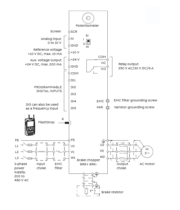
Wiring Details
Below image show control & power terminal details:
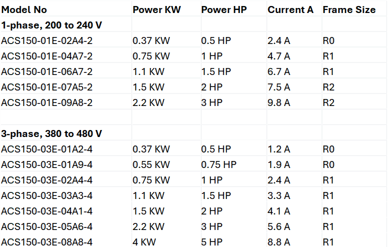
Drive Rating
Brake Resistance Details
| Part No. | Brake Resistor Minimum |
| 1-phase, 200 to 240 V | |
| ACS150-01X-02A4-2 | 70 ohm |
| ACS150-01X-04A7-2 | 40 ohm |
| ACS150-01X-06A7-2 | 40 ohm |
| ACS150-01X-07A5-2 | 30 ohm |
| ACS150-01X-09A8-2 | 30 ohm |
| 3-phase AC supply, 380 to 480 V | |
| ACS150-03X-01A2-4 | 200 ohm |
| ACS150-03X-01A9-4 | 175 ohm |
| ACS150-03X-02A4-4 | 165 ohm |
| ACS150-03X-03A3-4 | 150 ohm |
| ACS150-03X-04A1-4 | 130 ohm |
| ACS150-03X-05A6-4 | 100 ohm |
| ACS150-03X-07A3-4 | 70 ohm |
| ACS150-03X-08A8-4 | 70 ohm |
Faults & Alarms
Search from below list for ACS150 drive faults & alarms:
| Code | Cause & Solution | |
|---|---|---|
| A2001 OVERCURRENT | Cause: Output current limit controller is active. Solution: 1. Check motor load. 2. Check acceleration time (parameters 2202 ACCELER TIME 1 and 2205 ACCELER TIME 2). 3. Check motor and motor cable (including phasing). 4. Check ambient conditions. | |
| A2002 OVERVOLTAGE | Cause: DC overvoltage controller is active. Solution: 1. Check deceleration time (parameters 2203 DECELER TIME 1 and 2206 DECELER TIME 2). 2. Check input power line for static or transient overvoltage. | |
| A2003 UNDERVOLTAGE | Cause: DC undervoltage controller is active. Solution: Check input power supply. | |
| A2004 DIRLOCK | Cause: Change of direction is not allowed. Solution: Check parameter 1003 DIRECTION settings. | |
| A2006 AI1 LOSS | Cause: Analog input AI1 signal has fallen below limit defined by parameter 3021 AI1 FAULT LIMIT. Solution: 1. Check fault function parameter settings. 2. Check for proper analog control signal levels. 3. Check connections. | |
| A2009 DEVICE OVERTEMP | Cause: Drive IGBT temperature is excessive. Alarm limit is 120 °C. Solution: 1. Check ambient conditions. 2. Check air flow and fan operation. 3. Check motor power against drive power. | |
| A2010 MOTOR TEMP | Cause: Motor temperature is too high (or appears to be too high) due to excessive load, insufficient motor power, inadequate cooling or incorrect start-up data. Solution: 1. Check motor ratings, load and cooling. 2. Check start-up data. 3. Check fault function parameter settings. 4. Let motor cool down. 5. Ensure proper motor cooling: Check cooling fan, clean cooling surfaces, etc. | |
| A2011 UNDERLOAD | Cause: Motor load is too low due to, for example, release mechanism in driven equipment. Solution: 1. Check for problem in driven equipment. 2. Check fault function parameter settings. 3. Check motor power against drive power. | |
| A2012 MOTOR STALL | Cause: Motor is operating in stall region due to, for example, excessive load or insufficient motor power. Solution: 1. Check motor load and drive ratings. 2. Check fault function parameter settings. | |
| A2013 AUTORESET | Cause: Automatic reset alarm. Solution: Check parameter group 31 AUTOMATIC RESET settings. | |
| A2017 OFF BUTTON | Cause: Drive stop command has been given from control panel when local control lock is active. Solution: 1. Disable the local control mode lock by 1606 LOCAL LOCK and retry. | |
| A2018 PID SLEEP | Cause: Sleep function has entered the sleeping mode. Solution: See parameter group 40 PROCESS PID SET 1. | |
| A2023 EMERGENCY STOP | Cause: Drive has received emergency stop command and ramps to stop according to ramp time defined by parameter 2208 EMERG DEC TIME. Solution: 1. Check that it is safe to continue operation. 2. Return emergency stop push button to normal position. | |
| A2026 INPUT PHASE LOSS | Cause: Intermediate circuit DC voltage is oscillating due to missing input power line phase or blown fuse. Alarm is generated when DC voltage ripple exceeds 14% of nominal DC voltage. Solution: 1. Check input power line fuses. 2. Check for input power supply imbalance. 3. Check fault function parameter setting. 4. This is a programmable fault function, check parameter 3016 SUPPLY PHASE | |
| A5011 | Cause: Drive is controlled from another source. Solution: Change drive control to the local control mode. | |
| A5012 | Cause: Direction of rotation is locked. Solution: Enable change of direction. See parameter 1003 DIRECTION. | |
| A5013 | Cause: Panel control is disabled because start inhibit is active. Solution: 1. Start from the panel is not possible. Reset the emergency stop command or remove the 3-wire stop command before starting from the panel. 2. Check parameters 1001 EXT1 COMMANDS, 1002 EXT2 COMMANDS and 2109 EMERG STOP SEL. | |
| A5014 | Cause: Panel control is disabled because of drive fault. Solution: Reset drive fault and retry. | |
| A5015 | Cause: Panel control is disabled because the local control mode lock is active. Solution: Deactivate the local control mode lock and retry. See parameter 1606 LOCAL LOCK. | |
| A5019 | Cause: Writing non-zero parameter value is prohibited. Solution: Only parameter reset is allowed. | |
| A5022 | Cause: Parameter is write protected. Solution: Parameter value is read-only and cannot be changed. | |
| A5023 | Cause: Parameter change is not allowed, when drive is running. Solution: Stop drive and change parameter value. | |
| A5024 | Cause: Drive is executing task. Solution: Wait until task is completed. | |
| A5026 | Cause: Value is at or below minimum limit. | |
| A5027 | Cause: Value is at or above maximum limit. | |
| A5028 | Cause: Invalid value | |
| A5029 | Cause: Memory is not ready. Solution: Retry. | |
| A5030 | Cause: Invalid request | |
| A5031 | Cause: Drive is not ready for operation, for example, due to low DC voltage. Solution: Check input power supply. | |
| A5032 | Cause: Parameter error. | |
| F0001 OVERCURRENT | Cause: Output current has exceeded trip level. Overcurrent trip limit for drive is 325% of drive nominal current. Solution: 1. Check motor load. 2. Check acceleration time (parameters 2202 ACCELER TIME 1 and 2205 ACCELER TIME 2). 3. Check motor and motor cable (including phasing). 4. Check ambient conditions. Load capacity decreases if installation site ambient temperature exceed 40 °C. | |
| F0002 DC OVERVOLT | Cause: Excessive intermediate circuit DC voltage. DC overvoltage trip limit is 420 V for 200 V drives and 840 V for 400 V drives. Solutions: 1. Check that overvoltage controller is on (parameter 2005 OVERVOLT CTRL). 2. Check brake chopper and resistor (if used). DC overvoltage control must be deactivated when brake chopper and resistor are used. 3. Check deceleration time (parameters 2203 DECELER TIME 1 and 2206 DECELER TIME 2). 4. Check input power line for static or transient overvoltage. 5. Retrofit frequency converter with brake chopper and brake resistor. | |
| F0003 DEV OVERTEMP | Cause: Drive IGBT temperature is excessive. Fault trip limit is 135 °C. Solution: 1. Check ambient conditions. 2. Check air flow and fan operation. 3. Check motor power against drive power. | |
| F0004 SHORT CIRC | Cause: Short circuit in motor cable(s) or motor Solution: 1. Check motor and motor cable. | |
| F0006 DC UNDERVOLTAGE | Cause: Intermediate circuit DC voltage is not sufficient due to missing input power line phase, blown fuse, rectifier bridge internal fault or too low input power. Solution: 1. Check that undervoltage controller is on (parameter 2006 UNDERVOLT CTRL). 2. Check input power supply and fuses. | |
| F0007 AI1 LOSS | Cause: Analog input AI1 signal has fallen below limit defined by parameter 3021 AI1 FAULT LIMIT. Solution: 1. Check fault function parameter settings. 2. Check for proper analog control signal levels. 3. Check connections. | |
| F0009 MOT OVERTEMP | Cause: Motor temperature is too high (or appears to be too high) due to excessive load, insufficient motor power, inadequate cooling or incorrect start-up data. Solution: 1. Check motor ratings, load and cooling. 2. Check start-up data. 3. Check fault function parameter settings. 4. Let motor cool down. Ensure proper motor cooling: 5. Check cooling fan, clean cooling surfaces, etc. | |
| F0012 MOTOR STALL | Cause: Motor is operating in stall region due to, for example, excessive load or insufficient motor power. Solution: 1. Check motor load and drive ratings. 2. Check fault function parameter settings. | |
| F0014 EXT FAULT 1 | Cause: External fault 1 Check external devices for faults. Solution: 1. Check fault function parameter setting. | |
| F0015 EXT FAULT 2 | Cause: External fault 2 Solution: 1. Check external devices for faults. 2. Check fault function parameter setting. | |
| F0016 EARTH FAULT | Cause: Drive has detected earth (ground) fault in motor or motor cable. Solution: 1. Check motor. 2. Check motor cable. 3. Motor cable length must not exceed maximum specifications. Note: Disabling earth fault (ground fault) may damage drive. | |
| F0017 UNDERLOAD | Cause: Motor load is too low due to, for example, release mechanism in driven equipment. Solution: 1. Check for problem in driven equipment. 2. Check fault function parameter settings. 3. Check motor power against drive power. | |
| F0018 THERM FAIL | Cause: Drive internal fault. Thermistor used for drive internal temperature measurement is open or short-circuited. Solution: This hardware issue in drive need to repair or replace drive. | |
| F0021 CURR MEAS | Cause: Drive internal fault. Current measurement is out of range. Solution: This hardware issue in drive need to repair or replace drive. | |
| F0022 INPUT PHASE LOSS | Cause: Intermediate circuit DC voltage is oscillating due to missing input power line phase or blown fuse. Fault trip occurs when DC voltage ripple exceeds 14% of nominal DC voltage. Solution: 1. Check input power line fuses. 2. Check for input power supply imbalance. 3. Check fault function parameter setting. | |
F0026 DRIVE ID | Cause: Internal drive ID fault Solution: This hardware issue in drive need to repair or replace drive. | |
| F0027 CONFIG FILE | Cause: Internal configuration file error. Solution: This hardware issue in drive need to repair or replace drive. | |
| F0035 OUTPUT WIRING | Cause: Incorrect input power and motor cable connection (that is input power cable is connected to drive motor connection). Fault can be erroneously declared if drive is faulty or input power is delta grounded system and motor cable capacitance is large. Solution: 1. Check input power connections. 2. Check input & output connection. | |
| F0036 INCOMPATIBLE SW | Cause: Loaded software is not compatible. Solution: There is an hardware or software issue in drive, need to repaur or replace drive. | |
| F0101 SERF CORRUPT | Cause: Corrupted Serial Flash chip file system. Solution: There is an hardware or software issue in drive, need to repaur or replace drive. | |
| F0103 SERF MACRO | Cause: Active macro file missing from Serial Flash chip. Solution: There is an hardware or software issue in drive, need to repaur or replace drive. | |
| F0201 DSP T1 OVERLOAD | Cause: System error. Solution: There is an hardware or software issue in drive, need to repaur or replace drive. | |
| F0202 DSP T2 OVERLOAD | Cause: System error. Solution: There is an hardware or software issue in drive, need to repaur or replace drive. | |
| F0203 DSP T3 OVERLOAD | Cause: System error. Solution: There is an hardware or software issue in drive, need to repaur or replace drive. | |
| F0204 DSP STACK ERROR | Cause: System error. Solution: There is an hardware or software issue in drive, need to repaur or replace drive. | |
| F0206 MMIO ID ERROR | Cause: Internal I/O Control board (MMIO) fault. Solution: There is an hardware or software issue in drive, need to repaur or replace drive. | |
| F1000 PAR HZRPM | Cause: Incorrect speed/frequency limit parameter setting Solution: 1. Check parameter settings. 2. Following must apply: 2007 MINIMUM FREQ < 2008 MAXIMUM FREQ, 3. 2007 MINIMUM FREQ/9907 MOTOR NOM FREQ and 2008 MAXIMUM FREQ/9907 MOTOR NOM FREQ are within range. | |
| F1003 PAR AI SCALE | Cause: Incorrect analog input AI signal scaling Solution: 1. Check parameter group 13 ANALOG INPUTS settings. 2. Following must apply: 1301 MINIMUM AI1 < 1302 MAXIMUM AI1. |