Download Links
 Download Catalog Download Catalog |
Download Manual |
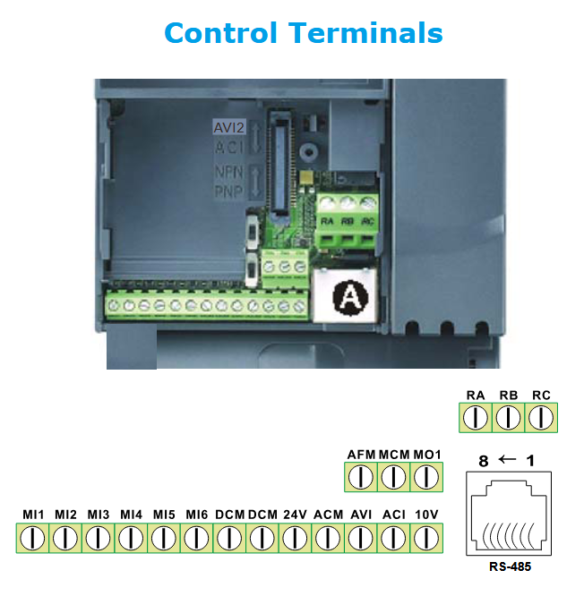
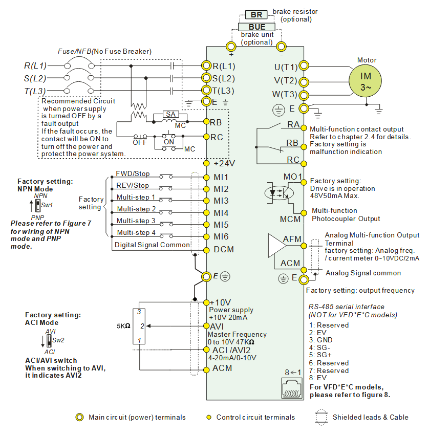
Wiring Details
Below image show terminal details:
Faults & Alarms
Search from below list for VFD-E series drive faults & alarms:
| Fault Code | Cause & Solution |
|---|---|
| bb External Base Block | Cause: This is a programmable fault (Refer to Pr. 08.07). Soultion: 1. When the external input terminal (B.B) is active, the AC motor drive output will be turned off. 2. Deactivate the external input terminal (B.B) to operate the AC motor drive again. |
| EF External fault | Cause: 1. When multi-function input terminals are set to external fault, the AC motor drive stops output. Soultion: 1. When multi-function input terminals (MI3-MI9) are set to external fault, the AC motor drive stops output U, V and W. 2. Give RESET command after fault has been cleared. |
| cE– Communication Fault | Cause: Communication Fault. Soultion: 1. Check the RJ45 connection between the AC motor drive for loose wires and wiring to the correct pins. 2. Check if the communication protocol is properly set. 3. Refer to Parameter Group 09 Communication Parameters in Chapter 4 for detailed information. |
| oc Overcurrent | Cause: Output current of the AC drive exceeds the OC level Soultion: – Extend the accel/decel time – Check whether the motor rating and the AC drive rating match up with each other – Check whether there is short-circuit among U-V-W of the AC drive – Check whether the wiring to the motor is short-circuited or grounded – Check whether the screw between the AC drive and the motor is tightened or not – Check whether the motor is over loaded |
| ov/ou overvoltage | Cause: DC voltage of the main circuit exceeds the over-voltage detection level – The DC bus voltage has exceeded its maximum allowable value. Soultion: – Check whether the input voltage is within the scope of the rated input voltage of the AC drive, and monitor whether there is any occurrence of the voltage transients – If it is of the motor inertia uprising voltage that caused the exceeding voltage on the DC high-voltage side within the AC drive, the solution is to extend the accel/decel time or install the braking resistor (optional) |
| oH1/oH2 Overheating | Cause: Overheating- Heat sink temperature too high Soultion: 1. Ensure that the ambient temperature falls within the specified temperature range. 2. Make sure that the ventilation holes are not obstructed. 3. Remove any foreign objects from the heatsinks and check for possible dirty heat sink fins. 4. Check the fan and clean it. 5. Provide enough spacing for adequate ventilation |
| Lu/Lv Low Voltage | Cause: DC high-voltage side is exceedingly low within the AC drive Soultion: – Check whether the input power voltage is normal – Check whether the loading will be put on another unexpected heavy loading – Whether the 3-phase model is of the single-phase power input or the phase-lacking |
| oL overload | Cause: AC drive overload- Output current exceeds the AC drive-bearable current; e.g. could sustain for 60 seconds if the output is 150% of the AC drive rated current. Soultion: – Decrease the loading and extend the acceleration time – Check whether the motor is overloaded – Reduce the torque compensation setting (Pr.07.02). – Increase the AC drive output capacity |
| oL1 Overload 1 | Cause: Overload 1- Internal electronic overload trip Soultion: 1. Check for possible motor overload. 2. Check electronic thermal overload setting. 3. Use a higher power motor. 4. Reduce the current level so that the drive output current does not exceed the value set by the Motor Rated Current Pr.07-00. |
| oL2 Motor overload | Cause: OL2- motor overload Motor with exceedingly great loading Soultion: – Check whether the loading of the motor is too great – Adjust the over-torque detection setting to an appropriate setting (Pr.06-03 to Pr.06-05). |
| HPF1 CC (current clamp) | Meaning: cc (current clamp) hardware protection error when power is ON. Cause & Solution: 1. Hardware failure – Cycle the power. 2. After this same fault comes then there is an hardware issue in drive need to repair or replace drive. |
| HPF2 OV hardware fault | Cause: OV hardware error Soultion: 1. Re-power on to try it. 2. After this same fault comes then there is an hardware issue in drive need to repair or replace drive. |
| HPF3 GFF hardware error | Cause: GFF hardware error Soultion: 1. Re-power on to try it. 2. After this same fault comes then there is an hardware issue in drive need to repair or replace drive. |
| HPF4 OC hardware fault | Cause: Oc hardware error Soultion: 1. Reboots the power. 2. After this same fault comes then there is an hardware issue in drive need to repair or replace drive. |
| bb External Base Block | Cause: This is a programmable fault (Refer to Pr. 08.07). Soultion: 1. When the external input terminal (B.B) is active, the AC motor drive output will be turned off. 2. Deactivate the external input terminal (B.B) to operate the AC motor drive again. |
| ocA Over-current during acceleration | Cause: Over-current during acceleration (Output current exceeds triple rated current during acceleration.). Soultion: 1. Short-circuit at motor output: Check for possible poor insulation at the output lines. 2. Acceleration Time too short: Increase the Acceleration Time. 3. AC motor drive output power is too small: Replace the AC motor drive with the next higher power model. |
| ocd Over-current during deceleration | Cause: Over-current during deceleration (Output current exceeds triple rated current during deceleration.) Soultion: 1. Short-circuit at motor output: Check for possible poor insulation at the output line. 2. Deceleration Time too short: Increase the Deceleration Time. 3. AC motor drive output power is too small: Replace the AC motor drive with the next higher power model. |
| ocn Over-current during steady state operation | Cause: Over-current during steady state operation (Output current exceeds triple rated current during constant speed.) Soultion: 1. Short-circuit at motor output: Check for possible poor insulation at the output line. 2. Sudden increase in motor loading: Check for possible motor stall. 3. AC motor drive output power is too small: Replace the AC motor drive with the next higher power model. |
| EF External fault | Cause: 1. When multi-function input terminals are set to external fault, the AC motor drive stops output. Soultion: 1. When multi-function input terminals (MI3-MI9) are set to external fault, the AC motor drive stops output U, V and W. 2. Give RESET command after fault has been cleared. |
| cF1.0 Internal EEPROM can not be programmed | Cause: Internal EEPROM can not be programmed. Soultion: 1. Press “RESET” key to the factory setting 2. After this same fault comes then there is an hardware issue in drive need to repair or replace drive. |
| cF1.1 Internal EEPROM can not be programmed | Cause: Internal EEPROM can not be programmed. Soultion: 1. Press “RESET” key to the factory setting 2. After this same fault comes then there is an hardware issue in drive need to repair or replace drive. |
| cF2.0 Internal EEPROM can not be read | Cause: Internal EEPROM can not be read. Soultion: 1. Press “RESET” key to the factory setting 2. After this same fault comes then there is an hardware issue in drive need to repair or replace drive. |
| cF2.1 Internal EEPROM can not be read | Cause: Internal EEPROM can not be read. Soultion: 1. Press “RESET” key to the factory setting 2. After this same fault comes then there is an hardware issue in drive need to repair or replace drive. |
| cF3.0 U-phase error | Cause: Wiring detection fault U-phase error. Soultion: There is an hardware or software issue in drive. Need to repair or replace drive. |
| cF3.1 V-phase error | Cause: Wiring detection fault V-phase error. Soultion: There is an hardware or software issue in drive. Need to repair or replace drive. |
| cF3.2 W-phase error | Cause: Wiring detection fault W-phase error. Soultion: There is an hardware or software issue in drive. Need to repair or replace drive. |
| cF3.3 Wiring detection (OV or LV) | Cause: DC bus wiring detection error.(OV or LV) Soultion: There is an hardware or software issue in drive. Need to repair or replace drive. |
| cF3.4 Wiring detection fault | Cause: Temperature sensor error. Soultion: There is an hardware or software issue in drive. Need to repair or replace drive. |
| GFF Ground Fault | Meaning: When the drive detects grounding short circuit on the output terminals (U/V/W), the drive closes the gate of the output immediately, the motor runs freely, and the display shows a GFF error. Cause & Solution: 1. Motor burnout or aging insulation occurred – Check the motor insulation value with megger. – Replace the motor if the insulation is poor. 2. Short circuit due to broken cable – Troubleshoot the short circuit. – Replace the cable. 3. Larger stray capacitance of the – cable and terminal – If the motor cable length exceeds 100 m, decrease the setting value for the carrier frequency. – Take remedies to reduce stray capacitance. 4. Malfunction caused by interference – Verify the grounding and wiring of the communication circuit. It is recommended to separate the communication circuit from the main circuit, or wire in 90 degree for effective anti-interference performance. 5. Hardware failure – Cycle the power after checking the status of motor, cable and cable length. If GFF still exists, return to the factory for repair. |
| cFA Auto accel/decel failure | Cause: Auto accel/decel failure. Soultion: 1. Check if the motor is suitable for operation by AC motor drive. 2. Check if the regenerative energy is too large. 3. Load may have changed suddenly. |
| cE– Communication Fault | Cause: Communication Fault. Soultion: 1. Check the RJ45 connection between the AC motor drive for loose wires and wiring to the correct pins. 2. Check if the communication protocol is properly set. 3. Refer to Parameter Group 09 Communication Parameters in Chapter 4 for detailed information. |
| CodE Software protection failure | Cause: Software protection failure.(Password locked) Soultion: There is an hardware or software issue in drive. Need to repair or replace drive. |
| AErr Analog signal error | Cause: Analog input current loss (including all analog 4–20 mA signals) – When the analog input is lower than 4 mA (only detects analog input 4–20 mA) Solution: 1. Loose or broken ACI wiring – Tighten the terminals again. – Replace with a new cable. 2. External device error – Replace with a new device. 3. Hardware error – If the AErr error still occurs after checking all the wiring, return to the factory for repair. |
| FbE PID feedback signal error | Cause: PID feedback signal error. Soultion: 1. Check the parameter settings (Pr.10.01) and AVI/ACI wiring. 2. Check for possible fault between the system response time and the PID feedback signal detection time (Pr.10.08) |
| PHL Phase loss | Cause: Power input phase-lacking Phase-lacking within the input power of the AC drive Three imbalanced conditions existed within the input voltage Soultion: – Check whether the power voltage is normal. – Check whether the screw at the input power terminal is tightened. |
| AUE Auto Tuning Fault | Cause: Motor auto-tuning error. Solution: 1. Press “STOP” key during auto-tuning – Re-execute auto-tuning. 2. Incorrect motor capacity (too large or too small) and parameter setting – Check motor capacity and related parameters. 3. Incorrect motor wiring – Check the wiring. 4. Motor shaft lock – Remove the cause of motor shaft lock. |
| CP10 Communication time-out | Cause: Communication time-out fault on the control board or power board. Soultion: 1. Press RESET key to set all parameters to factory setting. 2. After this same fault comes then there is an hardware issue in drive need to repair or replace drive. |
| PtC1/PtC2 Motor overheat protection | Cause: Motor overheat protection. Soultion: 1. Check if the motor is overheat 2. Check Pr.07.12 to Pr.07.17 settings |
| PGEr PG signal fault | Cause: PG signal fault. 1. Check the wiring of PG card. 2. Try another PG card. |
| CGUd CANopen Guarding Time out | Cause: CANopen Guarding Time out- When CANopen Node Guarding detects that one of the slaves does not respond. Soultion: Connect to CAN bus again and reset CAN bus. |
| CHbt CANopen Heartbeat Time out | Cause: CANopen Heartbeat Time out- When CANopen Heartbeat detects that one of the slaves does not response Soultion: 1. The heartbeat time is too short – Connect to CAN bus again and reset CAN bus 2. Malfunction caused by interference – Verify the wiring and grounding of the communication circuit. It is recommended to separate the communication circuit from the main circuit, or wire in 90 degree for effective anti-interference performance. – Make sure the communication circuit is wired in series. – Use CANopen cable or add terminating resistance. 3. Communication cable is broken or bad connected – Check or replace the communication cable. |
| CSYc CANopen SYNC Time out | Cause: CANopen SYNC Time out. Soultion: 1. Check if CANopen synchronous message is abnormal. |
| CSdo CANopen SDO Time out | Cause: CANopen SDO Time out. Soultion: 1. Check if command channels are full. |
| CSbF CANopen SDO buffer overflow | Cause: CANopen SDO buffer overflow. Soultion: 1. Too short time between commands, please check SDO message sent from the master 2. Reset CAN bus |
| CbSF CAN bus off | Cause: CAN bus off. Soultion: 1. Check if it connects to terminal resistor 2. Check if the signal is abnormal 3. Check if the master is connected |
| CbtU CAN Boot up fault | Cause: CAN Boot up fault Soultion: 1. Check if the master is connected 2. Reset CAN bus |
| CPto Fault communication protocol of CANopen | Cause: Fault communication protocol of CANopen. Soultion: 1. Check if the communication protocol is correct. |
| dEb | Cause: It will be displayed during deceleration when Pr.08-24 is not set to 0 and unexpected power off occurs, such as momentary power loss. Soultion: 1. Set Pr.08-24 to 0 2. Check if the input power is stable |
| AcL Abnormal Communication Loop | Cause: Abnormal Communication Loop. Soultion: 1. Check if the communication wiring is correct 2. After this same fault comes then there is an hardware issue in drive need to repair or replace drive. |
| cF01 Communication command fault | Cause: Communication command fault. Soultion: 1. Verify if there’s any fault occurred on communication command. |
| cF02 Communication address fault | Cause: Communication address fault. Soultion: 1. Verify if there’s any fault occurred on communication address. |
| cF03 Communication data fault | Cause: Communication data fault. Soultion: 1. Verify if there’s any fault occurred on communication data. |
| cF04 Communication format fault | Cause: Communication format fault Soultion: 1. Verify if there’s any fault occurred on communication format. |
| cF06 | Cause: Certain data are being processed so the motor drive is not responding at the moment. Soultion: The motor drive will respond after it processes some data. |
| cF10 Communication time out | Cause: Communication time out Soultion: 1. The communication time exceeds the setting at Pr09-03 2. Verify if the communication command is correct or if the data being transmitted is too big to send. |
| AoL2 oL2 Warning | When the motor drive’s output current is more than the detection level set at Pr06-04 and exceeds the detection time set at Pr06-05. The digital keypad (See Appendix B for more information) will display OL2. Press the RESET button on the digital keypad to clear the warning message. |
| AUE Motor auto-tuning | Cause: Motor auto-tuning. Soultion: Motor drive is performing the auto-tuning on parameters. As soon as the auto-tuning is done, an END message will be displayed. If there’s any fault occurred during the auto- tuning process, an Err message will be displayed. |
| SE1 Copying parameter(s) fails | Cause: Copying parameter(s) fails. Soultion: 1. Parameters cannot be copied. 2. Verify if there’s any fault occurred on the operation and the communication. 3. If there is no such fault and the parameters still cannot be copied, then there is an hardware issue in drive need to repair or replace drive. |
| SE2 | Cause: Parameter(s) copied cannot be written in. Soultion: Parameter(s) is/ are copied successfully but cannot be written in the motor drive. |
| PtC2 Motor drive PTC overheating warning | Cause: Motor drive PTC overheating warning Soultion: When the motor has PTC installed, the PTC function (Pr07-12) is enabled and the temperature reaches the overheating warning level (Pr07-15), this overheating issue will be treated by following the setting at Pr07-17. A PtC2 warning message will also be displayed on the digital keypad. |
| PGEr Warning on abnormal PG | Cause: Warning on abnormal PG. Soultion: 1. “PGEr” If the time for feedback signal exceeds the setting at Pr13-07, it will be considered as an abnormal feedback signal. 2. This issue will be treated by the setting at Pr.13.08 and a warning message PGEr will be displayed on the keypad. |
| FbE Warning on PID abnormal feedback signal | Cause: Warning on PID abnormal feedback signal Soultion: 1. If the PID feedback signal time exceeds the setting at Pr10-08, it will be considered as an abnormal feedback signal. 2. This issue will be treated by the setting at Pr10-09. |
| SAvE/SAuE | Cause: Parameter(s) is/are being written into the motor drive. Soultion: Parameter(s) is/are being written into the motor drive. As soon as that is done, a END message will be displayed on the keypad. |
| PE10 | Cause: Warning on USB card’s communication time out. Soultion: 1. If the USB card’s communication time is over the setting at Pr09-11, it will be considered as a time out. 2. This issue will be treated by the setting at Pr09-10. |
| AoFF | Cause: Warning on analogue input signal card. Soultion: The motor drive doesn’t receive data from analogue signal input card. |
| oPHL Output phase loss | Cause: Output phase loss of the drive. This fault also comes when you run drive without motor or one of phase is not connected. Warning on output phase loss Soultion: 1. Set Pr06-13=0, when one of the phases of the motor drive doesn’t do any output, a oPHL warning message will be displayed. 2. Verify if anything wrong on UVW output signal. |