Download Links
 Download Catalog Download Catalog |
Download Manual |
| Download Hardware Manual |
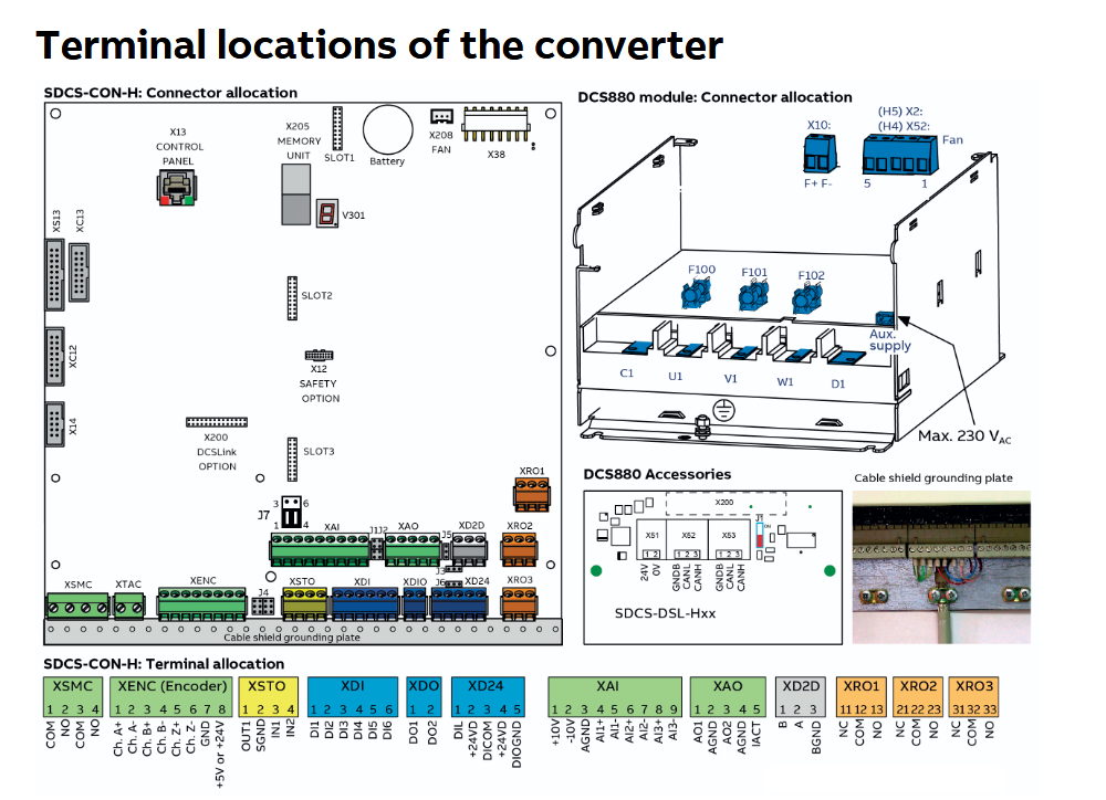
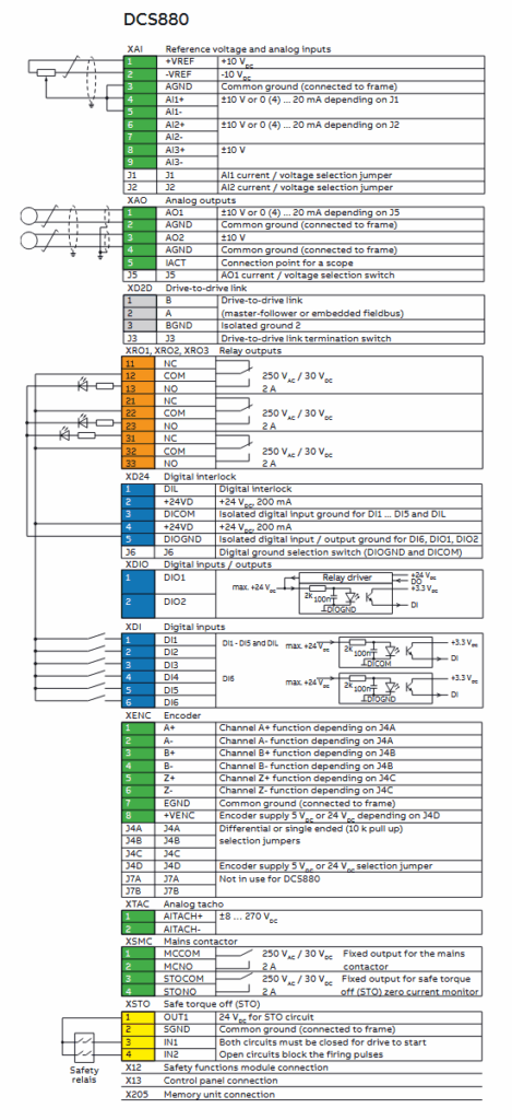
Wiring Details
Below image show terminal details:
Faults & Alarms
Search from below list for DCS880 drive faults & alarms:
| Fault Code | Cause & Solution |
|---|---|
| 1310 … 132F User defined | Cause: User defined warning. Solution: User defined warning by application program. |
| A103 DC-breaker acknowledge | Cause: Selected motor, DC-breaker acknowledge at the DI is missing. The firing angle is forced to the value of 30.45 Maximum firing angle and single firing pulses to suppress the DC current are given, thus the drive cannot be started or re-started while the DC breaker acknowledge is missing. Solution: Check: − The setting of 20.35 DC-breaker acknowledge source, if necessary invert the signal. |
| A104 Reversal volt function | Cause: Reversal volt function active. The armature voltage is too high compared to the mains voltage, before braking (switching from motoring to generating). Solution: Check: − If the setting of 31.61 Reversal volt delay is suitable for the system. − For too low mains voltage. See 99.01 Mains voltage. − Too high motor voltage. Lower 99.12 M1 nominal voltage and 99.14 M1 nominal (base) speed accordingly. − If the motor is accelerating during reversal e.g. hanging load. − The settings of the field current controller, EMF controller, flux linearization in group 28 EMF and field current control. E.g. field weakening is not activated. − For too high field current (e.g. problems with field weakening). − For overspeed. − For proper speed scaling. See 46.02 M1 speed scaling actual. − For proper armature voltage feedback. |
| A105 Dynamic braking acknowledge | Cause: Selected motor, dynamic braking is still pending. The firing angle is forced to the value of 30.45 Maximum firing angle and single firing pulses to suppress the DC current are given until zero speed is reached, thus the drive cannot be started or re-started while dynamic braking is active, except if 21.01 Start mode = Flying start dynamic braking. Solution: Check: − The setting of 20.43 Dynamic braking acknowledge source. − The setting of 21.01 Start mode. |
| A111 Mains low voltage | Cause: Mains/AC side low (under-) voltage. The firing angle is forced to the value of 30.45 Maximum firing angle and single firing pulses to suppress the DC current are given. Solution: Check: − The setting of 31.51. Mains loss mode, 31.52 Mains loss down time, 31.53 Mains loss low level 1 and 31.54 Mains loss low level 2. − That the mains voltage scaling is correct. See 99.10 Nominal mains voltage. − That the proper voltage coding resistors on the SDCS-PIN-H51 are used. − The condition of the mains (voltage, cabling, fuses, switchgear). − That all 3 phases are present directly at the drive. − H1 … H5: measure the fuses F100 … F102 on the SDCS-PIN-H01. − H6 … H8: check and measure the connections XU1/XU2, XV1/XV2 and XW1/XW2 on the SDCS-PIN-H51. − That the mains voltage is within the set tolerance. E.g. too deep mains voltage drops during load current. − For mains supply imbalance. − For loose mains cable connections. − That the mains contactor closes and opens and the timing. − For H1 … H4, that the field circuit has no short circuit or ground fault. − In case an On command is given, and the measured mains voltage is too low for longer than 500 ms warning A111 Mains low voltage is set. If the problem persists for longer than 10 s fault 3280 Mains low voltage is generated. |
| A112 P2P and M/F communication | Cause: DCSLink communication and DCSLink board (SDCS-DSL-H1x) communication loss. Solution: Check: − DCSLink node ID settings. See 70.05 DCSLink node ID. − The setting of 31.13 Fault stop mode communication and 70.07 DCSLink comm loss function. − The setting of 70.17 Mailbox 1 node ID, 70.23 Mailbox 2 node ID, 70.29 Mailbox 3 node ID and 70.35 Mailbox 4 node ID. − The setting of 70.18 Mailbox 1 cycle time/timeout, 70.24 Mailbox 2 cycle time/timeout, 70.30 Mailbox 3 cycle time/timeout and 70.36 Mailbox 4 cycle time/timeout. − The DCSLink cable connections. − The DCSLink terminations. |
| A113 Power unit communication | Cause: Communication errors between the control unit and a power unit. Solution: Check: − The connections between the control unit and the power unit: − The auxiliary power of the SDCS-OPL-H01. − The auxiliary code (format XXXYYYZZ). XXX specifies the transmitter FIFO error code. − 000: No transmitter FIFO error. − 001: Internal error [invalid call parameter]. − 002: Internal error [configuration not supported]. − 003: Transmission buffer full. YYY identifies the power unit. − 000: Broadcast. − 001: Power unit connected to channel1 on SDCS-DSL-H1x. − 002: Power unit connected to channel2 on SDCS-DSL-H1x. − 003: Power unit connected to channel3 on SDCS-DSL-H1x. − 004: Power unit connected to channel4 on SDCS-DSL-H1x. ZZ specifies the error source. − 01: Transmitter side [link error] from power unit to control unit. − 02: Transmitter side [no communication] from power unit to control unit. − 03: Receiver side [link error] from control unit to power unit. − 04: Receiver side [no communication] from control unit to power unit. − 05: Transmitter FIFO error, see XXX. − 06: SDCS-OPL-H01 not found. |
| A114 Armature current deviation | Cause: 27.02 Used current reference differs from 27.05 Motor current for longer than 5 s by more than 20 % of nominal motor current. If the current controller cannot match the given current reference, the warning signal is created. Normally the reason is a too small incoming voltage compared to the motor EMF. For non-motoric applications, it is possible to block the warning using 06.11.b07 Auxiliary control word 2. Solution: Check: − For blown DC fuses. − The ratio between mains voltage and armature voltage (either the mains voltage is too low, or the motor’s armature voltage is too high). − If the setting of 30.44 Minimum firing angle is too high. |
| A116 Brake long falling | Cause: Selected motor, the acknowledge signal for the mechanical brake closed (applied) stage at the DI is missing. Solution: Check: − The mechanical brake itself. − The mechanical brake cable connections. − The mechanical brake settings in group 44 Mechanical brake control. − That the acknowledgement signal, if used, matches the actual status of the brake. − The used digital inputs and outputs (groups 10 and 11). |
| A117 Armature current ripple | Cause: One or several thyristors may carry no current. Solution: Check: − The values of 01.50 Current ripple and 01.51 Current ripple filtered1. − The setting of 31.46 Current ripple function and 31.47 Current ripple level. − For too high gain of current controller. See 27.29 M1 current proportional gain. − For too fast rise of the current reference. − The positive/negative current feedback with an oscilloscope (6 pulses within one cycle visible?). − The thyristor gate-cathode resistance. − The thyristor gate connection. − The current transformers (T51, T52). − The condition of the mains (voltage, cabling, fuses, switchgear). |
| A118 Application | Cause: Application file new or different. Solution: 1. Check the AUX code. Actions see below. 0001 Found a new application on the memory unit. Activate the application on the memory unit by means of 96.16 Parameter save manually = Enable application. 0002 Application in drive memory and on memory unit are different. Activate the application on the memory unit by means of 96.16 Parameter save manually = Enable application. |
| A120 Overvoltage protection active | Cause: The overvoltage protection DCF506 of a large field exciter is active and the field exciter is blocked. Notes: − Only valid if 99.06 Operation mode = Large field exciter. − The DO of the DCF506 must be connected to a DI of the large field exciter. See 20.47 Overvoltage protection trigger source. − This alarm typically pops up for a short time, when the field current changes its direction. The firing angle is forced to the value of 30.45 Maximum firing angle and single firing pulses to suppress the field current are given. Solution: Check: − The setting of 20.47 Overvoltage protection trigger source if necessary invert the signal. − The field converter cables and connections. |
| A124 Speed scaling | Cause & Solution: The settings of: − 30.11 M1 minimum speed. − 30.12 M1 maximum speed. − 31.30 M1 overspeed trip margin. − 46.01 M1 speed scaling. − 99.14 M1 nominal (base) speed. Must be set in a range of 0.1 … 1.6 • 46.02 M1 speed scaling actual (1.6 = 32000/20000). − The parameters causing the warning can be identified in the AUX code (format YYZZ). YY specifies the parameter group. ZZ specifies the parameter number. The firing angle is forced to the value of 30.45 Maximum firing angle and single firing pulses to suppress the DC current are given. |
| A130 Mains phase loss | Cause: One or several mains voltage phase(s) are missing, or the mains voltage phases are imbalanced. The firing angle is forced to the value of 30.45 Maximum firing angle and single firing pulses to suppress the DC current are given. Solution: Check: − The condition of the mains (voltage, cabling, fuses, switchgear). − That all 3 phases are present directly at the drive. − H1 … H5: measure the fuses F100 … F102 on the SDCS-PIN-H01. − H6 … H8: check and measure the connections XU1/XU2, XV1/XV2 and XW1/XW2 on the SDCS-PIN-H51. − For mains supply imbalance. − For loose mains cable connections. − That the mains contactor closes and opens. − The AUX code: − 0: All phase voltages U (L1), V (L2) and W (L3) are missing. − 1: Mains voltage phases are imbalanced. Phase-to- phase voltage UUV is the smallest voltage. − 2: Mains voltage phases are imbalanced. Phase-to- phase voltage UVW is the smallest voltage. − 3: Phase V (L2) is missing. − 4: Mains voltage phases are imbalanced. Phase-to- phase voltage UWU is the smallest voltage. − 5: Phase U (L1) is missing. − 6: Phase W (L3) is missing. |
| A131 PLL deviation | Cause: PLL deviation level is exceeded and the current controller is blocked. See also 06.25.b13 Current controller status word 2. The firing angle is forced to the value of 30.45 Maximum firing angle and single firing pulses to suppress the DC current are given. Solution: Check: − For an instable mains voltage. − For a too fast armature current rise. − 95.39 PLL input deviation. − 95.40 PLL output, internal mains frequency. − 95.43 PLL offset synchronization transformer. − 95.44 PLL deviation level. − 95.45 PLL proportional gain. − 95.46 PLL filter time. − 95.47 PLL Uk compensation. |
| A132 Parameter setting conflict | Cause & Solution: Parameter settings conflicting with other parameters. The parameters causing the warning can be identified in the AUX code (format YYZZ YYZZ). YY specifies the parameter group. In case of 00, see the actions below. ZZ specifies the parameter number or the actions below. Additionally check: − 95.25 Set: Type code for proper value. 0070 No field reversal possible due to 28.54 Field current force direction = External reverse. 0071 Flux linearization parameters not consistent. See 28.31 Field current at 40 % flux, 28.32 Field current at 70 % flux and 28.33 Field current at 90 % flux. 0077 Encoder 1 parameters not consistent. Check: − 46.02 M1 speed scaling actual or 42.14 M2 speed scaling actual. − 92.10 Pulses/revolution. − 92.11 Pulse encoder type.0078 Encoder 2 parameters not consistent. Check: − 46.02 M1 speed scaling actual or 42.14 M2 speed scaling actual. − 93.10 Pulses/revolution. − 93.11 Pulse encoder type. |
| A137 Start condition conflict | Cause: Re-start of the drive is not possible. Solution: Check: − The AUX code (format XXXX 00YY). XXXX specifies the parameter group and number e.g.: − 0619: 06.19 Drive inhibit status word 2. − 0620: 06.20 Run inhibit status word. − 9524: 95.24 Service mode ≠ Normal mode. YY specifies the bit showing the reason, if applicable. |
| A2B3 Residual current detected | Cause: The drive has detected an unbalance typically due to a residual current in the motor or the motor cables. Sum of IL1 , IL2 , IL3 ≠ zero. Solution: Check: − The settings of 31.17 Residual current detection source, 31.18 Residual current detection type, 31.19 Residual current detection level and 31.20 Residual current detection delay. − The sum current transformer, if necessary change transformer or connected drive hardware. − The insulation resistances of motor and motor cables. Disconnect the mains, verify safe isolation from supply in armature and field circuits and make insulation tests for the complete installation. |
| A490 Incorrect temperature sensor setup | Cause: Problem with motor temperature measurement. Solution: Check the AUX code (format 0XYYZZZZ). X identifies the affected temperature monitoring function. 0 = parameter 35.11. 1 = parameter 35.21. YY indicates the selected temperature source, e.g. the setting of the selection parameter in hexadecimal. ZZZZ indicates the problem. Actions see below. 0001 Sensor type mismatch. – Check parameters 35.11/35.21 against 91.21/91.24. 0002 Temperature under limit. – Check parameters 35.11 … 35.14/ 35.21 … 35.24 and 91.21/91.24 if the sensor is connected to an encoder interface. Check the sensor and its wiring. 0003 Short circuit. – Check parameters 35.11 … 35.14/ 35.21 … 35.24 and 91.21/91.24 if the sensor is connected to an encoder interface. Check the sensor and its wiring. 0004 Open circuit. – Check parameters 35.11 … 35.14/ 35.21 … 35.24 and 91.21/91.24 if the sensor is connected to an encoder interface. Check the sensor and its wiring. |
| A491 Motor temperature 1 measured/estimated | Cause: Measured/Estimated motor temperature 1 has exceeded the warning level. Wait until the motor/motor model is cooled down. The fan contactor stays on as long as the warning is pending. Solution: Check: − The value of 35.02 Measured temperature 1. − The real motor temperature. Let motor cool down and restart. − The value of 35.13 Temperature 1 warning level. − The cooling of the motor or other temperature measured equipment. − The ambient conditions (e.g. ambient temperature). − The airflow and fan operation. − The motor fan supply voltage. − The motor fan direction of rotation. − The motor fan components. − The motor cooling air inlet (e.g. filters). − The motor cooling air outlet. − The motor load and drive ratings. − Inadmissible load cycle. − The wiring of the temperature sensor. − The resistance of the temperature sensor by measuring it. |
| A492 Motor temperature 2 measured/estimated | Cause: Measured/Estimated motor temperature 2 has exceeded the warning level. Wait until the motor/motor model is cooled down. The fan contactor stays on as long as the warning is pending. Solution: Check: − The value of 35.03 Measured temperature 2. − The real motor temperature. Let motor cool down and restart. − The value of 35.23 Temperature 2 warning level. − The cooling of the motor or other temperature measured equipment. − The ambient conditions (e.g. ambient temperature). − The airflow and fan operation. − The motor fan supply voltage. − The motor fan direction of rotation. − The motor fan components. − The motor cooling air inlet (e.g. filters). − The motor cooling air outlet. − The motor load and drive ratings. − Inadmissible load cycle. − The wiring of the temperature sensor. − The resistance of the temperature sensor by measuring it. Hint: − The measured/estimated motor temperature is blocked, if 35.21 Temperature 2 source = Disable. |
| A497 Motor temperature slot 1 measured | Cause: The thermistor protection module (FEN- xx or FPTC-xx) installed in slot 1 indicates overtemperature. Depending on the used module, a PTC and/or KTY temperature sensor can be attached. Solution: Check: − The cooling of the motor or other temperature measured equipment. − The motor load and drive ratings. − The wiring of the temperature sensor. − The resistance of the temperature sensor by measuring it. |
| A498 Motor temperature slot 2 measured | Cause: The thermistor protection module (FEN- xx or FPTC-xx) installed in slot 2 indicates overtemperature. Depending on the used module, a PTC and/or KTY temperature sensor can be attached. Solution: Check: − The cooling of the motor or other temperature measured equipment. − The motor load and drive ratings. − The wiring of the temperature sensor. − The resistance of the temperature sensor by measuring it. |
| A499 Motor temperature slot 3 measured | Cause: The thermistor protection module (FEN- xx or FPTC-xx) installed in slot 3 indicates overtemperature. Depending on the used module, a PTC and/or KTY temperature sensor can be attached. Solution: Check: − The cooling of the motor or other temperature measured equipment. − The motor load and drive ratings. − The wiring of the temperature sensor. − The resistance of the temperature sensor by measuring it. |
| A4A0 Control board temperature measured | Cause: Excessive control board temperature. Solution: Check the AUX code (format XXXXZZZZ). ZZZZ indicates the problem. Actions see below. None Temperature above warning limit of xx °C or xx °F. Check: − The value of 05.10 Control board temperature. − The ambient conditions. − The airflow and fan operation. − The heatsink fins for dust pick-up. 0001 Thermistor broken. |
| A4B0 Bridge temperature measured | Cause: Excessive bridge temperature. Wait until the bridge is cooled down. The fan contactor stays on as long as the warning is pending. Shutdown temperature, see 07.65 Drive max bridge temperature set. The bridge overtemperature warning will already appear at approximately 5°C below the shutdown temperature. Solution: Check: − The values of 05.11 Ch1 bridge temperature … 05.14 Ch4 bridge temperature. − The setting of 20.38 Drive fan acknowledge source. − The setting of 20.40 Drive/Motor fan delay time. − The ambient conditions (e.g. ambient temperature). − The airflow and fan operation. − The drive fan supply voltage. − The drive fan direction of rotation. − The drive fan components. − The heatsink fins for dust pick-up. − The drive cooling air inlet (e.g. filters). − The drive cooling air outlet. − For open drive doors. − The motor power against the drive power. − Inadmissible load cycle. − When 95.25 Set: Type code = None, that 95.29 Set: Drive max bridge temperature is set properly. − The AUX code (format XXXYYYZZ). YYY identifies the power unit channel. In case of a hardparallel configuration. |
| A534 12-pulse current difference | Cause: The current of difference of a 12-pulse parallel configuration exceeded the current difference level. Solution: Check: − The settings of 29.07 12-pulse parallel current difference level and 29.08 12-pulse parallel current difference delay. − The settings of the current controller in group 27 Armature current control. |
| A560 Power unit, unbalanced current | Cause: The unbalanced current between hardparallel connected power units is excessive. Solution: Check: − That the mains and motor cable routing is according to the specification for hardparallel configurations. − The branch fuses. − The thyristors. − The AUX code (format XXXYYYZZ). YYY identifies the power unit channel. ZZ identifies the affected thyristor. Example: 00000314 means thyristor 14 in the power unit connected to channel3. |
| A561 Power unit, thyristor loss function | Cause: Displays the thyristors/branch fuses of a power unit which are lost, in other words not conducting any current. Solution: Check: − The branch fuses. − The thyristors. − The AUX code (format XXXYYYZZ). YYY identifies the power unit channel. ZZ identifies the affected thyristor. Example: 00000314 means thyristor14 in the power unit connected to channel3. |
| A581 Drive fan acknowledge | Cause: Drive cooling fan feedback at the DI is missing. Solution: Check: − The settings of 20.38 Drive fan acknowledge source and 20.40 Drive/Motor fan delay time. − The drive fan operation and connection. − The drive fan contactor. − The drive fan circuit. − The drive fan klixon. − The drive fan components. − The drive fan supply voltage. − The drive fan direction of rotation. − The drive door open. − The drive cooling air inlet (e.g. filter). − The drive cooling air outlet. − H7 and H8 pressure switch (setting should be 2 mbar). − The used digital inputs and outputs (groups 10 and 11). |
| A596 12-pulse slave blocked | Cause: The 12-pulse slave is preventing the 12-pulse master from starting. Solution: Check: − Warnings in the 12-pulse slave. Note: The warning level depends on the 12-pulse slave warning level. |
| A5A0 Safe torque off | Cause: Safe torque off active, no drive problem. Solution: Check: − 31.22 STO indication run/stop. − The safe torque off circuit. |
| A5A3 Safe off mains contactor XSMC:STO | Cause: Safe torque off monitor DC current not zero (zero current time out). The DCS880 has the possibility to open the mains contactor using a hardware supervision of the DC current in case of a safe torque off request. This is called fault shutdown path. In case safe torque off is requested and current zero is detected in less than 300 ms the XSMC:STO relay is kept closed. In case safe torque off is requested and current zero is not detected in less than 300 ms the XSMC:STO relay is opened and the fault shutdown path becomes active. Solution: Check: − For defective parts (e.g. thyristors) in the unit. − The SDCS-CON-H01. − For high inductive loads. |
| A5F4 Control board battery | Cause: The battery on the SDCS-CON-H01 is low. Solution: Exchange the battery. |
| A682 Flash erase speed exceeded | Cause: The flash memory in the memory unit has been erased too frequently. This compromises the lifetime of the memory. Avoid forcing unnecessary parameter saves by 96.16 Parameter save manually or cyclic parameter writes. E.g. user logger triggering via parameters. Solution: 1. Check the AUX code (format XYYYYZZZ). X specifies the source of warning. − 1: Generic flash memory erase supervision. ZZZ specifies the flash memory subsector number that generated the warning. |
| A6B0 User lock open | Cause: The user lock is open and parameters 96.100 … 96.102 are visible. Solution: Close the user lock by entering an invalid pass code in 96.07 Pass code. |
| A6B1 User pass code not confirmed | Cause & Solution: A new user pass code has been entered, but not confirmed yet. A new user pass code has been entered in 96.100 Change user pass code. Confirm the new pass code by entering the same code in 96.101 Confirm user pass code. To cancel, close the user lock without confirming the new code. To close the user lock, enter an invalid user pass code into 96.07 Pass code then activate 96.27 Control board boot or cycle the power. |
| A6D1 FBA A parameter conflict | Cause: Fieldbus adapter A (FBA A): The drive does not have a functionality requested by a PLC or a requested functionality has not been activated. The settings of parameter groups 50 Fieldbus adapter (FBA) and 51 FBA A settings are not set according to the fieldbus adapter or the device has not been selected. Solution: Check: − The PLC programming.− The settings of parameter groups 50 Fieldbus adapter (FBA) and 51 FBA A settings. − The configuration of the fieldbus adapter. |
| A6D2 FBA B parameter conflict | Cause: Fieldbus adapter B (FBA B): The drive does not have a functionality requested by a PLC or a requested functionality has not been activated. The settings of parameter groups 50 Fieldbus adapter (FBA) and 54 FBA B settings are not set according to the fieldbus adapter or the device has not been selected. Solution: Check: − The PLC programming. − The settings of parameter groups 50 Fieldbus adapter (FBA) and 54 FBA B settings. − The configuration of the fieldbus adapter. |
| A6DA Reference source parametrization | Cause: A reference source is simultaneously connected to multiple parameters with different units. See also 65B1. Solution: Check: − The reference source selection parameters. − The AUX code (format YYZZ). YY specifies the parameter group. ZZ specifies the parameter number. |
| A6E5 AI parametrization | Cause: The current/voltage hardware setting of an analog input does not correspond to the parameter settings. Solution: Check the AUX code. The code identifies the analog input whose settings are in conflict. Adjust either the jumper (J1, J2) setting on the control board or parameters 12.15, 12.25. |
| A6E6 ULC configuration | Cause: User load curve configuration error. Solution: 1. Check the AUX code (format XXXXZZZZ). ZZZZ indicates the problem. Actions see below. 0000 Speed points inconsistent. Check that each speed point, see parameters 37.11 … 37.15, has a higher value than the previous point. 0002 Underload point above overload point. Check that each overload point, see parameters 37.31 … 37.35, has a higher value than the corresponding underload point, see parameters 37.21 … 37.25. 0003 Overload point below underload point. Check that each overload point, see parameters 37.31 … 37.35, has a higher value than the corresponding underload point, see parameters 37.21 … 37.25. |
| AA780 Motor stall | Cause: Selected motor, the motor is operating in the stall region because of excessive load or insufficient motor power. The motor torque exceeded 31.25 Stall torque level for a time longer than 31.28 Stall time while the speed feedback was below 31.26 Stall speed level. Solution: Check: − The motor load/mechanics (e.g. brake). − The drive ratings. − For correct field current. − The settings of 31.24 Stall function, 31.25 Stall torque level, 31.26 Stall speed level and 31.28 Stall time. − The settings for current and torque limits in group 30 Control limits. |
| A781 Motor fan acknowledge | Cause: Motor/External cooling fan feedback at the DI is missing. Solution: Check: − The setting of 20.39 Motor fan acknowledge source. − The fan operation and connection. Replace the motor/external fan if faulty. − The fan contactor. − The fan supply voltage. |
| A782 Measurement circuit FEN temperature | Cause 1: Problem with the temperature measurement when a FEN-xx is used. Solution: Check that 35.11 Temperature 1 source and 35.21 Temperature 2 source setting corresponds to the actual installation connected to the encoder interface. Cause 2: Problem with the temperature measurement when a FEN-01 is used. Solution: A non-supported KTY sensor is connected to the encoder interface FEN-01. Use either a PTC sensor or another encoder interface module. |
| A797 Speed feedback configuration | Cause: The speed feedback configuration via encoder interface modules has changed. Solution: Check the AUX code (format XXYYZZZZ). XX specifies the encoder interface module. − 01: For module 1 see parameters 91.11 and 91.12. − 02: For module 2 see parameters 91.13 and 91.14. YY specifies the encoder. − 01: Group 92 Encoder 1 configuration. − 02: Group 93 Encoder 2 configuration. ZZZZ indicates the problem. Actions see below. 0001 Adapter not found in specified slot. Check module location. See parameters 91.12 and 91.14. 0002 Detected type of interface module does not match parameter setting. Check the module type parameters 91.11 and 91.13 against status parameters 91.02 and 91.03. 0003 Logic version too old. 0004 Firmware version too old. 0006 Encoder type incompatible with interface module type. Check module type parameters 91.11 and 91.13 against encoder type parameters 92.01 and 93.01. 0007 Adapter not configured. Check module location parameters 91.12 and 91.14. 0008 Speed feedback configuration has changed. Use 91.10 Encoder parameter refresh to validate any changes in the settings. 0009 No encoders configured in the encoder module. Configure the encoder in group 92 Encoder 1 configuration or 93 Encoder 2 configuration. 000A Non-existing emulation input. Check input selection parameters 91.31 and 91.41. 000B Echo not supported by the selected input. E.g. resolver or absolute encoder.Check: − The input selection parameters 91.31 and 91.41. − The interface module type against the encoder type. 000C Emulation in continuous mode not supported. Check: − The input selection parameters 91.31 and 91.41. − The serial link mode parameters 92.30 and 93.30. |
| A798 Encoder interface communication | Cause: Measured motor/load feedback via an encoder interface module is lost. Solution: Check: − That the encoder interface module is properly seated in its slot. − That the encoder interface module or slot connectors are not damaged. To pinpoint the problem, try installing the module into another slot. − The AUX code (format XXXXYYYY). YYYY indicates the problem. Actions see below. 0001 Failed answer to encoder configuration message. 0002 Failed answer to adapter watchdog disable message. 0003 Failed answer to adapter watchdog enable message. 0004 Failed answer to adapter configuration message. 0005 Too many failed answers inline to speed and position messages. 0006 DDCS driver failed. |
| A7A1 Mechanical brake closing failed | Cause: Selected motor, the acknowledge signal for the mechanical brake closed (applied) stage at the DI is missing. Solution: Check: − The mechanical brake itself. − The mechanical brake cable connections. − The mechanical brake settings in group 44 Mechanical brake control. − That the acknowledgement signal, if used, matches the actual status of the brake. − The used digital inputs and outputs (groups 10 and 11). |
| A7A2 Mechanical brake opening failed | Cause: Selected motor, the acknowledge signal for the mechanical brake opened (lifted) stage at the DI is missing. Solution: Check: − The mechanical brake itself. − The mechanical brake cable connections. − The mechanical brake settings in group 44 Mechanical brake control. − That the acknowledgement signal, if used, matches actual status of brake. − The used digital inputs and outputs (groups 10 and 11). |
| A7A5 Mechanical brake opening not allowed | Cause: Selected motor, open (lift) conditions of the mechanical brake are not fulfilled. The brake has been prevented from opening (lifting) by 44.11 M1 keep brake closed, 44.12 M1 Brake close request or torque actual does not reach 44.26 M1 Torque proving reference, during torque proving. Solution: Check: − The mechanical brake settings in group 44 Mechanical brake control. Especially 44.11 M1 keep brake closed and 44.12 M1 Brake close request. − That the acknowledgement signal, if used, matches the actual status of the brake. − The used digital inputs and outputs (groups 10 and 11). |
| A7AA Extension AI parameterization | Cause: The hardware current/voltage and parameter settings do not match for an analog input on an I/O extension module. Solution: 1. Check the AUX code (format XX0000YY). XX specifies the number of the I/O extension module. − 01: Group 14 I/O extension module 1. − 02: Group 15 I/O extension module 2. − 03: Group 16 I/O extension module 3. YY specifies the analog input on the module. |
| A7AB I/O extension configuration | Cause: The I/O extension module/DCSLink board (SDCS-DSL-H1x) types and locations specified by parameters do not match the detected configuration or do not communicate with the drive. Solution: Check: − The type and location settings of the modules/board. See parameters 14.01, 14.02, 15.01, 15.02, 16.01, 16.02, 70.01, 70.02, 70.05, 70.07 and 95.16. − That the module/board is properly seated in its slot. − That the module/board and the slot connector is not damaged. − Try installing the module into another slot. − Check the AUX code (format XXYYYYYY). XX specifies the number of the I/O extension module. − 01: Group 14 I/O extension module 1. − 02: Group 15 I/O extension module 2. − 03: Group 16 I/O extension module 3. − 04: Group 70 DCSLink Communication or group 95 HW configuration. YYYYYY indicates the problem. Actions see below. 000001 Communication with module/board failed. 000002 Module/Board not found. 000003 Configuration of module/board failed. |
| A7B0 Motor speed feedback | Cause: Selected motor, no motor speed feedback is received. Solution: Check the AUX code (format XXYYZZZZ). XX specifies the location of the speed feedback device. Either an encoder interface module or the control board. − 01: Encoder interface module 1, see parameters 91.11 and 91.12. − 02: Encoder interface module 2, see parameters 91.13 and 91.14. − 03: Control board, see group 94 OnBoard speed feedback configuration. YY specifies the speed feedback device. − 01: Encoder 1, see group 92 Encoder 1 configuration. − 02: Encoder 2, see group 93 Encoder 2 configuration. − 03: OnBoard encoder, see group 94 OnBoard speed feedback configuration. − 04: Tacho, see group 94 OnBoard speed feedback configuration. ZZZZ indicates the problem. Actions see below. 0001 Motor gear definition invalid or outside limits. Check motor gear settings. See 90.43 Motor gear numerator and 90.44 Motor gear denominator. This warning is always active independent of 31.35 Motor feedback fault. 0002 Speed feedback device not configured. Check the settings of the speed feedback device: − Encoder 1, see group 92 Encoder 1 configuration. − Encoder 2, see group 93 Encoder 2 configuration. − The OnBoard encoder, see group 94 OnBoard speed feedback configuration. − The tacho, see group 94 OnBoard speed feedback configuration. Use 91.10 Encoder parameter refresh to validate any changes in the settings for an encoder. 0003 Speed feedback device stopped working. Check the status of the speed feedback device. 0004 Speed feedback device drift detected. Check for slippage between speed feedback device and motor. 0007 The comparison of the measured speed feedback from pulse encoder or analog tacho to measured EMF has failed. Check: − The setting of 90.41 M1 feedback selection, 31.14 Fault stop mode fault level 3, 31.35 Motor feedback fault, 31.36 Speed feedback monitor level and 31.37 EMF feedback monitor level. − At the encoder: The encoder itself, alignment, cabling, coupling, power supply (feedback might be too low), mechanical disturbances, jumper J4 on the SDCS-CON- H01. − At the tacho: The tacho itself, tacho polarity and voltage, alignment, cabling, coupling, mechanical disturbances.− EMF: The armature cable connection form the drive to the motor and the polarity. |
| A7B1 Load speed feedback | Cause: Selected motor, no load speed feedback is received. Attention: The warning can only be reset by setting 96.27 Control board boot = Reboot or by cycling the auxiliary power. Solution: Check the AUX code (format XXYYZZZZ). XX specifies the location of the speed feedback device. Either an encoder interface module or the control board. − 01: Encoder interface module 1, see parameters 91.11 and 91.12. − 02: Encoder interface module 2, see parameters 91.13 and 91.14. − 03: Control board, see group 94 OnBoard speed feedback configuration. YY specifies the speed feedback device. − 01: Encoder 1, see group 92 Encoder 1 configuration. − 02: Encoder 2, see group 93 Encoder 2 configuration. − 03: OnBoard encoder, see group 94 OnBoard speed feedback configuration. − 04: Tacho, see group 94 OnBoard speed feedback configuration. ZZZZ indicates the problem. Actions see below. 0001 Load gear definition invalid or outside limits. Check load gear settings. See 90.53 Load gear numerator and 90.54 Load gear denominator. This warning is always active independent of 31.38 Load feedback fault. 0002 Feed constant definition invalid or outside limits. Check feed constant settings. See 90.63 Feed constant numerator and 90.64 Feed constant denominator. This warning is always active independent of 31.38 Load feedback fault. 0003 Motor/Load gear definition invalid or outside limits. Check motor/load gear settings. See 90.61 Gear numerator and 90.62 Gear denominator. This warning is always active independent of 31.38 Load feedback fault. 0004 Speed feedback device not configured. Check the settings of the speed feedback device: − Encoder 1, see group 92 Encoder 1 configuration. − Encoder 2, see group 93 Encoder 2 configuration. − The OnBoard encoder, see group 94 OnBoard speed feedback configuration. − The tacho, see group 94 OnBoard speed feedback configuration. Use 91.10 Encoder parameter refresh to validate any changes in the settings for an encoder. 0005 Speed feedback device stopped working. Check the status of the speed feedback device.0007 The comparison of the measured speed feedback from pulse encoder or analog tacho to measured EMF has failed. Check: − The setting of 90.41 M1 feedback selection, 31.14 Fault stop mode fault level 3, 31.35 Motor feedback fault, 31.36 Speed feedback monitor level and 31.37 EMF feedback monitor level. − At the encoder: The encoder itself, alignment, cabling, coupling, power supply (feedback might be too low), mechanical disturbances, jumper J4 on the SDCS-CON- H01. − At the tacho: The tacho itself, tacho polarity and voltage, alignment, cabling, coupling, mechanical disturbances. − EMF: The armature cable connection form the drive to the motor and the polarity. |
| A7C1 FBA A communication | Cause: Fieldbus adapter A (FBA A): Cyclical communication between PLC and fieldbus adapter module A or between drive and fieldbus adapter module A is lost. Fault 7510 FBA A communication is only activated after the first data set from the overriding control is received by the drive. Before the first data set is received, only warning A7C1 FBA A communication is active. The reason is to suppress unnecessary faults (the startup of the overriding control is usually slower than the one of the drive). Solution: Check: − The status of the fieldbus communication. See user documentation of the fieldbus interface. − The settings of groups 50 Fieldbus adapter (FBA), 51 FBA A settings, 52 FBA A data in and 53 FBA A data out. − The cable connections. − The fieldbus cable termination. − The fieldbus adapter. − That the master can communicate. |
| A7C2 FBA B communication | Cause: Fieldbus adapter B (FBA B): Cyclical communication between PLC and fieldbus adapter module B or between drive and fieldbus adapter module B is lost. Fault 7520 FBA B communication is only activated after the first data set from the overriding control is received by the drive. Before the first data set is received, only warning A7C2 FBA B communication is active. The reason is to suppress unnecessary faults (the startup of the overriding control is usually slower than the one of the drive). Solution: Check: − The status of the fieldbus communication. See user documentation of the fieldbus interface. − The settings of group 50 Fieldbus adapter (FBA), 54 FBA B settings, 55 FBA B data in and 56 FBA B data out. − The cable connections. − The fieldbus cable termination. − The fieldbus adapter. − That the master can communicate. |
| A7CA DDCS controller communication | Cause: Cyclical communication between DDCS controller and drive is lost or there is no communication at all. The drive is waiting for the very first data set. Solution: Check: − The status/settings of the DDCS controller. See user documentation of the DDCS controller. − The adapters between DDCS controller and drive. − The setting of 20.01 Command location. − The settings of group 60 DDCS communication, 61 D2D and DDCS transmit data and 62 D2D and DDCS receive data. − The fiber optic cable connections. |
| A7CB Master-follower link communication | Cause: Cyclical communication between master and a follower (DDCS/D2D) is lost or there is no communication at all. The drive is waiting for the very first data set. Solution: Check: − The AUX code. It indicates which node address on the master-follower link is affected. See 60.02 M/F node address in each drive. − The setting of 60.14 M/F follower selection. − The setting of 20.01 Command location. − The settings of group 60 DDCS communication. − The cable connections. |
| A7CE EFB communication | Cause: Cyclical communication to the embedded fieldbus (EFB) is lost. Fault 6681 EFB communication is only activated after the first data set from the overriding control is received by the drive. Before the first data set is received, only warning A7CE EFB communication is active. The reason is to suppress unnecessary faults (the startup of the overriding control is usually slower than the one of the drive). Solution: Check: − The status of the fieldbus master (online, offline, error etc.). − The settings of group 58 FBA Embedded fieldbus. − The cable connections to connector XD2D on the control board. − The fieldbus cable termination. |
| A7DC FSx undefined warning | See FSPS-21 PROFIsafe safety functions module (AXD50000158638). |
| A7E1 Speed feedback device | Cause: Speed feedback device error. Solution: Check the AUX code (format XXYYZZZZ). XX specifies the location of the speed feedback device. Either an encoder interface module or the control board. − 01: Encoder interface module 1, see parameters 91.11 and 91.12. − 02: Encoder interface module 2, see parameters 91.13 and 91.14. − 03: Control board, see group 94 OnBoard speed feedback configuration. YY specifies the speed feedback device. − 01: Encoder 1, see group 92 Encoder 1 configuration. − 02: Encoder 2, see group 93 Encoder 2 configuration. − 03: OnBoard encoder, see group 94 OnBoard speed feedback configuration. − 04: Tacho, see group 94 OnBoard speed feedback configuration. − 05: EMF, see group 94 OnBoard speed feedback configuration. ZZZZ indicates the problem. Actions see below. 0001 Cable fault. If the encoder was working previously, check the encoder, encoder cable and encoder interface module for damage. Check: − The conductor order at both ends of the encoder cable. − The groundings of the encoder cable. − 92.21 Encoder cable fault mode. − 94.29 OnBoard encoder cable fault mode. 0002 No encoder signal. Check the condition of the encoder. 0003 Overspeed.0004 Overfrequency. 0005 Resolver ID run failed. 0006 Resolver overcurrent. 0008 Absolute encoder communication error. 0009 Absolute encoder initialization error. 000A Absolute SSI encoder configuration error. |
| A7EE Control panel/PC tool link communication | Cause: This alarm occurs even though no control is expected from the control panel/PC tool. The control panel/PC tool connected via USB or the PC tool connected via FENA-11/21 has stopped communicating. Solution: Check: − The setting of 49.04 Communication loss time. If needed extend the time out to 2000 ms. Do not forget to verify the setting by means of 49.06 Refresh settings Refresh. − The setting of 49.05 Communication loss action. If changed, do not forget to verify the setting by means of 49.06 Refresh settings Refresh. − The control panel/PC tool connection/cable. − The control panel connector. − The mounting platform if being used (e.g. DPMP-01). − Disconnect and reconnect the control panel/PC tool. |
| A880 Motor bearings | Cause: Warning generated by an on-time timer or a value counter. Solution: 1. See group 33 Generic timer & counter. 2. Check the AUX code for the source of the warning. − 0: 33.13 On-time 1 source. − 1: 33.23 On-time 2 source. − 4: 33.53 Value counter 1 source. − 5: 33.63 Value counter 2 source. |
| A881 Output relay | Cause: Warning generated by an edge counter. Solution: See group 33 Generic timer & counter. |
| A882 Motor starts | Cause: Warning generated by an edge counter. Solution: See group 33 Generic timer & counter. |
| A883 Power ups | Cause: Warning generated by an edge counter. Solution: See group 33 Generic timer & counter. |
| A884 Mains contactor | Cause: Programmable warnings, see 33.35 Edge counter 1 warn message and 33.45 Edge counter 2 warn message. Solution: Check the AUX code for the source of the warning. − 2: 33.33 Edge counter 1 source. − 3: 33.43 Edge counter 2 source. |
| A885 DC-breaker | Cause: Programmable warnings, see 33.35 Edge counter 1 warn message and 33.45 Edge counter 2 warn message. Solution: Check the AUX code for the source of the warning. − 2: 33.33 Edge counter 1 source. − 3: 33.43 Edge counter 2 source. |
| A886 On-time 1 | Cause: Warning generated by on-time timer 1. See group 33 Generic timer & counter. Solution: 1. Check the source of the warning. See 33.13 On-time 1 source. |
A887 On-time 2 | Cause: Warning generated by on-time timer 2. See group 33 Generic timer & counter. Solution: 1. Check the source of the warning. See 33.23 On-time 2 source. |
| A888 Edge counter 1 | Cause: Warning generated by edge counter 1. See group 33 Generic timer & counter. Solution: 1. Check the source of the warning. See 33.33 Edge counter 1 source. |
| A889 Edge counter 2 | Cause: Warning generated by edge counter 2. See group 33 Generic timer & counter. Solution: 1. Check the source of the warning. See 33.43 Edge counter 2 source. |
| A88A Value counter 1 | Cause: Warning generated by value counter 1. See group 33 Generic timer & counter. Solution: 1. Check the source of the warning. See 33.53 Value counter 1 source. |
| A88B Value counter 2 | Cause: Warning generated by value counter 2. See group 33 Generic timer & counter. Solution: 1. Check the source of the warning. See 33.63 Value counter 2 source. |
| A88C Clean device | Cause: Warning generated by an on-time timer. See group 33 Generic timer & counter. Programmable warnings, see 33.14 On-time 1 warn message and 33.24 On-time 2 warn message. Solution: 1. Check the AUX code for the source of the warning. − 0: 33.13 On-time 1 source. − 1: 33.23 On-time 2 source. − 10: 05.04 Fan on-time counter. |
| A88D Any fan | Cause: Warning generated by an on-time timer. See group 33 Generic timer & counter. Programmable warnings, see 33.14 On-time 1 warn message and 33.24 On-time 2 warn message. Solution: 1. Check the AUX code for the source of the warning. − 0: 33.13 On-time 1 source. − 1: 33.23 On-time 2 source. − 10: 05.04 Fan on-time counter. |
| A88E Cabinet fan | Cause: Warning generated by an on-time timer. See group 33 Generic timer & counter. Programmable warnings, see 33.14 On-time 1 warn message and 33.24 On-time 2 warn message. Solution: 1. Check the AUX code for the source of the warning. − 0: 33.13 On-time 1 source. − 1: 33.23 On-time 2 source. − 10: 05.04 Fan on-time counter. |
| A88F Cooling fan | Cause: Warning generated by an on-time timer. See group 33 Generic timer & counter. Programmable warnings, see 33.14 On-time 1 warn message and 33.24 On-time 2 warn message. Solution: 1. Check the AUX code for the source of the warning. − 0: 33.13 On-time 1 source. − 1: 33.23 On-time 2 source. − 10: 05.04 Fan on-time counter. |
| A890 Additional cooling fan | Cause: Warning generated by an on-time timer. See group 33 Generic timer & counter. Programmable warnings, see 33.14 On-time 1 warn message and 33.24 On-time 2 warn message. Solution: 1. Check the AUX code for the source of the warning. − 0: 33.13 On-time 1 source. − 1: 33.23 On-time 2 source. − 10: 05.04 Fan on-time counter. |
| A8A0 AI supervision | Cause: An analog signal is outside the limits specified for the analog input. Solution: Check: − The AUX code (format XYY). X specifies the location of the input. − 0: Control board. − 1: I/O extension module 1. − 2: I/O extension module 2 − 3: I/O extension module 3. − 4: …. YY specifies the input and limit. − 01: AI1 under minimum. − 02: AI1 over maximum. − 03: AI2 under minimum. − 04: AI2 over maximum. − 05: AI3 under minimum. − 06: AI3 over maximum. − The signal level at the analog input. − The wiring connected to the input. − Polarity of the connection. − The minimum and maximum limits of the input in groups 12 Standard AI, 14 I/O extension module 1, 15 I/O extension module 2 and 16 I/O extension module 3. |
| A8B0 Signal supervision 1 | Cause: Warning generated by signal supervision 1. See group 32 Supervision. Solution: Check the source of the warning. See 32.07 Supervision 1 signal. |
| A8B1 Signal supervision 2 | Cause: Warning generated by signal supervision 2. See group 32 Supervision. Solution: 1. Check the source of the warning. See 32.17 Supervision 2 signal. |
| A8B2 Signal supervision 3 | Cause: Warning generated by signal supervision 3. See group 32 Supervision. Solution: 1. Check the source of the warning. See 32.27 Supervision 3 signal. |
| A8BE ULC overload | Cause: Selected signal has exceeded the user overload curve. See group 37 User load curve. Solution: Check: − For any operating conditions increasing the monitored signal. E.g., the load of the motor if the torque or current is being monitored. − The definition of the load curve. |
| A8BF ULC underload | Cause: Selected signal has fallen below the user underload curve. See group 37 User load curve. Solution: Check: − For any operating conditions decreasing the monitored signal. E.g., the loss of load if the torque or current is being monitored. − The definition of the load curve. |
| A8C0 Fan service counter | Cause: A cooling fan has reached the end of its estimated lifetime. See 05.41 Main fan service counter. Solution: 1. Check the AUX code for the fan to be replaced. − 0: Main cooling fan. − 1: Auxiliary cooling fan. − 2: Auxiliary cooling fan 2. − 3: Cabinet cooling fan. |
| A981 External warning 1 | Cause: There is no problem with the drive itself! Warning generated by external device 1. See group 31 Fault functions and fault levels. Solution: 1. Check: − External device 1. − 31.01 External event 1 source. |
| A982 External warning 2 | Cause: There is no problem with the drive itself! Warning generated by external device 2. See group 31 Fault functions and fault levels. Solution: Check: − External device 2. − 31.03 External event 2 source. |
| A983 External warning 3 | Cause: There is no problem with the drive itself! Warning generated by external device 3. See group 31 Fault functions and fault levels. Solution: Check: − External device 3. − 31.05 External event 3 source. |
| A984 External warning 4 | Cause: There is no problem with the drive itself! Warning generated by external device 4. See group 31 Fault functions and fault levels. Solution: Check: − External device 4. − 31.07 External event 4 source. |
| A985 External warning 5 | Cause: There is no problem with the drive itself! Warning generated by external device 5. See group 31 Fault functions and fault levels. Solution: Check: − External device 5. − 31.09 External event 5 source. |
| AF8C Process PID sleep mode | Cause: Reserved . |
| AF90 Autotuning | Cause: The autotuning or assistant did not complete successfully. To clear the warning, either finish an autotuning/assistant successfully or keep Reset (e.g. via DI) depressed for over 3 seconds. Solution: Check the AUX code (format XXXXYYYY). XXXX specifies the autotuning or assistant. − 0001: Field current autotuning. − 0002: Armature current autotuning. − 0003: Speed feedback assistant. − 0004: Speed controller autotuning. − 0005: EMF controller autotuning. − 0006: Flux linearization autotuning. − 0007: Thyristor test. For drives size H5 … H8 make sure, that 99.11 M1 nominal current is set to 50 A or higher. − 0008: Tacho fine tuning. YYYY indicates the problem. Actions see below. 00010001 − The drive was stopped before the autotuning finished. − The On command was prematurely removed. − Autotuning aborted by a fault. Repeat autotuning until successful. 00010002 Motor is turning. No speed zero indication. 00010003 Armature current not zero. 00010004 Field current autotuning wrongly started in armature drive, please use the field exciter. 00010005 No field exciter selected. See 99.07 M1 used field exciter type. 00010006 Autotuning timeout, On command was not set in time. 00010007 … 0001000A − Measured field current does not reach the field current reference. − No detection of field resistance. − Field circuit open (e.g. not connected) respectively interrupted. 0001000B Unable to detect a field inductance. 0001000C Firmware fault. 00020002 − The drive was stopped before the autotuning finished. − The Run command was prematurely removed. − Autotuning aborted by a fault. Repeat autotuning until successful. 00020003 Autotuning timeout, Run command was not set in time or is missing. 00020004 − Invalid nominal armature current setting. − Armature current 99.11 M1 nominal current is set to zero. 00020005 Motor is turning. No speed zero indication. 00020006 Armature circuit and/or armature voltage measurement circuit wrongly connected (e.g. at C1/D1 or at the SDCS-PIN- H51). 00020007 No load connected to armature circuit. 00020008 Armature voltage measurement circuit open (e.g. not connected at C1/D1 or at the SDCS-PIN-H51) or interrupted. This can be checked by measuring the motor resistance at C1/D1 and the SDCS-PIN-H51. Check also current and torque limits. 00020009 Firmware fault. 00030001 − The drive was stopped before the autotuning finished. − The Run command was prematurely removed. − Autotuning aborted by a fault. Repeat autotuning until successful. 00030002 Tuning of speed controller, speed feedback assistant or tacho fine-tuning not possible due to speed limitation. See 30.11 M1 minimum speed and 30.12 M1 maximum speed. 00030003 Tuning of speed controller, speed feedback assistant or tacho fine-tuning not possible due to voltage limitation. During the tuning of the speed controller, the speed feedback assistant or the tacho fine-tuning base speed, 99.14 M1 nominal (base) speed, might be reached. Thus, full armature voltage, 99.12 M1 nominal voltage, is necessary. In case the mains voltage is too low to provide for the needed armature voltage the autotuning procedure is canceled. Check and adapt if needed: − 99.10 Nominal mains voltage. − 99.12 M1 nominal voltage. − 99.14 M1 nominal (base) speed. 00030004 Autotuning timeout, Run command was not set in time or is missing. 00030005 Motor could not accelerate to base speed. Decrease 23.12 Acceleration time 1 to get more torque and current. 00030006 Tacho adjustment faulty or not OK or the tacho voltage is too high during autotuning 00040001 − The drive was stopped before the autotuning finished. − The Run command was prematurely removed. − Autotuning aborted by a fault. Repeat autotuning until successful. 00040002 Autotuning timeout, Run command was not set in time or is missing. 00040003 Tuning of speed controller, speed feedback assistant or tacho fine-tuning not possible due to speed limitation. See 30.11 M1 minimum speed and 30.12 M1 maximum speed. 00040004 … 00040006 Motor is turning. No speed zero indication. 00040007 Motor could not decelerate with full autotuning torque. 00040008 Armature current not zero. 00040009 Tuning of speed controller, speed feedback assistant or tacho fine-tuning not possible due to voltage limitation. During the tuning of the speed controller, the speed feedback assistant or the tacho fine-tuning base speed, 99.14 M1 nominal (base) speed, might be reached. Thus, full armature voltage, 99.12 M1 nominal voltage, is necessary. In case the mains voltage is too low to provide for the needed armature voltage the autotuning procedure is canceled. Check and adapt if needed: − 99.10 Nominal mains voltage. − 99.12 M1 nominal voltage. − 99.14 M1 nominal (base) speed. 0004000A Required torque reference could not be reached before the drive reached base speed. 0004000B Drive is not in speed control mode. See 19.01 Actual operation mode. 0004000C Motor could not accelerate to base speed. Decrease 23.12 Acceleration time 1 to get more torque and current. 0004000D No writing of control parameters of speed controller possible. 0004000E Firmware fault. |
| AFE1 Off2 (emergency off) | Cause: The drive has received an Off2 command (emergency off/fast current off). There is no problem with the drive itself! Solution: Check: − The AUX code (format 00XXYYYY). XX specifies the source of the Off2 command. − 04: 20.04 Off2 source 1 (emergency off). − 08: 20.08 Off2 source 2 (emergency off). − 09: 06.09.b01 Used main control word. YYYY specifies the digital input or bit. − 0000: Other [bit]; source selection. − 0100: Off2 command; 0, emergency off/fast current off. − 0101: Off2 inactive; 1, normal operation. − 0103: DI1; 10.02.b00 DI delayed status. − 0104: DI2; 10.02.b01 DI delayed status. − 0105: DI3; 10.02.b02 DI delayed status. − 0106: DI4; 10.02.b03 DI delayed status. − 0107: DI5; 10.02.b04 DI delayed status. − 0108: DI6; 10.02.b05 DI delayed status. − 0111: DIO1; 11.02.b00 DIO delayed status. − 0112: DIO2; 11.02.b01 DIO delayed status. − 0119: DIL; 10.02.b15 DI delayed status. − 1001: 06.09.b01 Used main control word. − That it is safe to continue operation. − That it is safe to reset the source of the Off2 command. E.g. a push button. Then restart the drive. − If necessary, invert the signal, since the signal should be low active. − If On/Run command is still high. |
| AFE2 Off3 (emergency stop) | Cause: The drive has received an Off3 command (emergency stop). There is no problem with the drive itself! Solution: Check: − The AUX code (format 00XXYYYY). XX specifies the source of the Off3 command. − 01: 200.05.b02 FSO control word 1. − 05: 20.05 Off3 source (emergency stop). − 09: 06.09.b02 Used main control word. YYYY specifies the digital input or bit. − 0000: Other [bit]; source selection. − 0100: Off3 command; 0, emergency stop. − 0101: Off3 inactive; 1, normal operation. − 0103: DI1; 10.02.b00 DI delayed status. − 0104: DI2; 10.02.b01 DI delayed status. − 0105: DI3; 10.02.b02 DI delayed status. − 0106: DI4; 10.02.b03 DI delayed status. − 0107: DI5; 10.02.b04 DI delayed status. − 0108: DI6; 10.02.b05 DI delayed status. − 0111: DIO1; 11.02.b00 DIO delayed status. − 0112: DIO2; 11.02.b01 DIO delayed status. − 0119: DIL; 10.02.b15 DI delayed status. − 1002: 06.09.b02 Used main control word. − 1003: 200.05.b02 FSO control word 1. − That it is safe to continue operation. − That it is safe to reset the source of the Off3 command. E.g. a push button. Then restart the drive. − If necessary, invert the signal, since the signal should be low active. − If On/Run command is still high. |
| AFE7 Follower | Cause: A follower has tripped. Solution: 1. Check the AUX code to find out the node address of the faulted follower. See 60.02 M/F node address. 2. Correct the fault in the follower. |
| B5A0 Safe torque off | Cause: Safe torque off active, no drive problem. Solution: 1. See Safety supplement for functional safety converter DCS880 (3ADW000452). 2. Check: − 31.22 STO indication run/stop. − The safe torque off circuit. |
| B5A3 Safe off mains contactor XSMC:STO | Cause: Safe torque off monitor DC current not zero (zero current time out). The DCS880 has the possibility to open the mains contactor using a hardware supervision of the DC current in case of a safe torque off request. This is called fault shutdown path. In case safe torque off is requested and current zero is detected in less than 300 ms the XSMC:STO relay is kept closed. In case safe torque off is requested and current zero is not detected in less than 300 ms the XSMC:STO relay is opened and the fault shutdown path becomes active. Solution: Check: − For broken parts (e.g. thyristors) in the unit. − The SDCS-CON-H01. − For high inductive loads. |
| B5A4 Firmware internal diagnostics | Cause: The control board rebooted unexpectedly. |
| F1411 CU logic error | Cause: The CPU of the control board, at some point, writes a value into a FPGA register and repeatedly reads the register. If the read value is not what the CPU thinks is correct, then it generates fault 1411 CU logic error. Possible causes could be, that: − The FPGA has been reset due to a disturbed mains/auxiliary voltage (e.g. a voltage dip). − The FPGA has been reset due to a loss of the clock signal or too high interference in the clock signal. Solution: Check: − The firmware version. See 07.05 Firmware version. − For any mains/auxiliary voltage network issues when the fault happens. − For strong disturbances when the fault happens. E.g. the start of a big machine etc. − How many drives are affected. − When several drives trip, if the trip happens at the same time (simultaneously) or if the drives trip one by one. |
| F1412 Fault reset | Cause: A fault has been reset. |
| F1414 Backup/Restore Timeout | Cause: The unit encountered problems creating a backup file or restoring one. Please try again. Solution: Check: − The control panel/PC-tool communication and if it is still in backup/restore state. |
| F2310 Armature overcurrent | Cause: The armature current has exceeded either 07.63 Drive DC overcurrent level or 31.44 Armature overcurrent level. Solution: Check: − That the start-up data in group 99 corresponds to the motor rating plate and that the drive is matching the motor. − The setting of 07.63 Drive DC overcurrent level and 31.44 Armature overcurrent level. If tripping while using the DCS880 Assistant, set 31.44 Armature overcurrent level = 230.00 %. When finished, set back to the original value. − The settings of the current controller in group 27 Armature current control. − The settings of current and torque limits in group 30 Control limits. − The motor and motor cables. − All connections in the armature circuit. − The incoming voltage for synchronizing. If the synchronizing voltage is not taken from the mains directly, but via a synchronizing transformer or the 230 VAC /115 VAC network, check that there is no phase shift between the same phases. Use an oscilloscope to verify. − The mains/branch fuses. − The thyristors. − That there are no contactors opening and closing in the motor cables. − That there are no power factor correction capacitors or surge absorbers between line reactor and drive. − The AUX code (format XXXYYYZZ). YYY identifies the power unit channel. In case of a hardparallel configuration. ZZ identifies the cause: − 01: Overcurrent in 27.05 Motor current. − 02: Overcurrent in 27.06 Motor peak current. In case of a rebuild kit check: − For proper connection of the firing pulses. − For proper connection of the CTs. − That 95.25 Set: Type code = None. − The setting of 95.27 Set: Drive DC current scaling, because 07.63 Drive DC overcurrent level = 2.3 • 95.27 Set: Drive DC current scaling. |
| F2330 Residual current detected | Cause: The drive has detected an unbalance typically due to a residual current in the motor or the motor cables. Sum of IL1, IL2, IL3 ≠ zero. Solution: Check: − The settings of 31.17 Residual current detection source, 31.18 Residual current detection type, 31.19 Residual current detection level and 31.20 Residual current detection delay. − The insulation resistances of motor and motor cables. Disconnect the mains, verify safe isolation from supply in armature and field circuits and make insulation tests for the complete installation.− The residual current transformer, if necessary change transformer or connected drive hardware. |
| F3130 Mains phase loss | Cause: One or several mains voltage phase(s) are missing, or the mains voltage phases are imbalanced. The firing angle is forced to the value of 30.45 Maximum firing angle and single firing pulses to suppress the DC current are given. Solution: Check: − The condition of the mains (voltage, cabling, fuses, switchgear). − That all 3 phases are present directly at the drive. − H1 … H5: measure the fuses F100 … F102 on the SDCS-PIN-H01. − H6 … H8: check and measure the connections XU1/XU2, XV1/XV2 and XW1/XW2 on the SDCS- PIN-H51. − For mains supply imbalance. − For loose mains cable connections. − That the mains contactor closes and opens. − The AUX code: − 0: All phase voltages U (L1), V (L2) and W (L3) are missing. − 1: Mains voltage phases are imbalanced. Phase- to-phase voltage UUV is the smallest voltage. − 2: Mains voltage phases are imbalanced. Phase- to-phase voltage UVW is the smallest voltage. − 3: Phase V (L2) is missing. − 4: Mains voltage phases are imbalanced. Phase- to-phase voltage UWU is the smallest voltage. − 5: Phase U (L1) is missing. − 6: Phase W (L3) is missing. |
| F3280 Mains low voltage | Cause: Mains low (under-) voltage (AC side). The firing angle is forced to the value of 30.45 Maximum firing angle and single firing pulses to suppress the DC current are given. Solution: Check: − The setting of 31.51. Mains loss mode, 31.52 Mains loss down time, 31.53 Mains loss low level 1 and 31.54 Mains loss low level 2. − That the mains voltage scaling is correct. See 99.10 Nominal mains voltage. − The cutting of the voltage coding resistors on the SDCS-PIN-H51. − The condition of the mains (voltage, cabling, fuses, switchgear). − That all 3 phases are present directly at the drive. − H1 … H5: measure the fuses F100 … F102 on the SDCS-PIN-H01. − H6 … H8: check and measure the connections XU1/XU2, XV1/XV2 and XW1/XW2 on the SDCS- PIN-H51.− That the mains voltage is within the set tolerance. − For mains supply imbalance. − For loose mains cable connections. − That the mains contactor closes and opens. − For H1 … H4, that the field circuit has no short circuit or ground fault. − In case an On command is given, and the measured mains voltage is too low for longer than 500 ms A111 Mains low voltage is set. If the problem persists for longer than 10 s 3280 Mains low voltage is generated. |
| F4310 Bridge temperature measured | Cause: Excessive bridge temperature. Wait until the bridge is cooled down. The fan contactor stays on as long as the fault is pending. Temperature fault level, see 07.65 Drive max bridge temperature set. The bridge overtemperature warning will already appear at approximately 5°C below the temperature fault level. Solution: Check: − The values of 05.11 Ch1 bridge temperature … 05.14 Ch4 bridge temperature. − The setting of 20.38 Drive fan acknowledge source. − The setting of 20.40 Drive/Motor fan delay time. − The ambient conditions (e.g. ambient temperature). − The airflow and fan operation. − The drive fan supply voltage. − The drive fan direction of rotation. − The drive fan components. − The heatsink fins for dust pick-up. − The drive cooling air inlet (e.g. filters). − The drive cooling air outlet. − For open drive doors. − The motor power against the drive power. − Inadmissible load cycle. − When 95.25 Set: Type code = None, that 95.29 Set: Drive max bridge temperature is set properly. − The AUX code (format XXXYYYZZ). YYY identifies the power unit channel. In case of a hardparallel configuration. |
| F4981 Motor temperature 1 measured/ estimated | Cause: Measured/Estimated motor temperature 1 has exceeded the fault level. Wait until the motor/motor model is cooled down under the warning level. The fan contactor stays on as long as the fault is pending. It is not possible to reset the fault as long as the motor remains too hot. Solution: Check: − The value of 35.02 Measured temperature 1. − The real motor temperature. Let motor cool down and restart. − The value of 35.12 Temperature 1 fault level. − The setting of 35.15 Supervision 1 klixon source, if klixons are used. − The cooling of the motor or other temperature measured equipment.− The ambient conditions (e.g. ambient temperature). − The airflow and fan operation. − The motor fan supply voltage. − The motor fan direction of rotation. − The motor fan components. − The motor cooling air inlet (e.g. filters). − The motor cooling air outlet. − The motor load and drive ratings. − Inadmissible load cycle. − The wiring of the temperature sensor. − The resistance of the temperature sensor by measuring it. Hint: − The measured/estimated motor temperature is blocked, if 35.11 Temperature 1 source = Disable. |
| F4982 Motor temperature 2 measured/ estimated | Cause: Measured/Estimated motor temperature 2 has exceeded the fault level. Wait until the motor/motor model is cooled down under the warning level. The fan contactor stays on as long as the fault is pending. It is not possible to reset the fault as long as the motor remains too hot. Solution: Check: − The value of 35.03 Measured temperature 2. − The real motor temperature. Let motor cool down and restart. − The value of 35.22 Temperature 2 fault level. − The setting of 35.25 Supervision 2 klixon source, if klixons are used. − The cooling of the motor or other temperature measured equipment. − The ambient conditions (e.g. ambient temperature). − The airflow and fan operation. − The motor fan supply voltage. − The motor fan direction of rotation. − The motor fan components. − The motor cooling air inlet (e.g. filters). − The motor cooling air outlet. − The motor load and drive ratings. − Inadmissible load cycle. − The wiring of the temperature sensor. − The resistance of the temperature sensor by measuring it. Hint: − The measured/estimated motor temperature is blocked, if 35.21 Temperature 2 source = Disable. |
| 4990 FPTC-xx module not found | Cause & Solution: A thermistor protection module (FPTC-xx) was activated in 35.30 FPTC configuration word, but it is not detected. Power down the drive/control unit and make sure that the module is properly inserted in the correct slot. The last digit of the AUX code identifies the slot. |
| F4991 Motor temperature slot 1 measured | Cause: The thermistor protection module (FEN-xx or FPTC-xx) installed in slot 1 indicates overtemperature. Solution: 1. KTY temperature sensor can be attached. 2. Check: − The cooling of the motor or other temperature measured equipment. − The motor load and drive ratings. − The wiring of the temperature sensor. − The resistance of the temperature sensor by measuring it. |
| F4992 Motor temperature slot 2 measured | Cause: The thermistor protection module (FEN-xx or FPTC-xx) installed in slot 2 indicates overtemperature. Solution: 1. KTY temperature sensor can be attached. 2. Check: − The cooling of the motor or other temperature measured equipment. − The motor load and drive ratings. − The wiring of the temperature sensor. − The resistance of the temperature sensor by measuring it. |
| F4993 Motor temperature slot 3 measured | Cause: The thermistor protection module (FEN-xx or FPTC-xx) installed in slot 3 indicates overtemperature. Solution: 1. KTY temperature sensor can be attached. 2. Check: − The cooling of the motor or other temperature measured equipment. − The motor load and drive ratings. − The wiring of the temperature sensor. − The resistance of the temperature sensor by measuring it. |
| F5080 Drive fan acknowledge | Cause: Drive cooling fan feedback at the DI is missing. Solution: Check: − The settings of 20.38 Drive fan acknowledge source and 20.40 Drive/Motor fan delay time. − The drive fan operation and connection. − The drive fan contactor. − The drive fan circuit. − The drive fan klixon. − The drive fan components. − The drive fan supply voltage. − The drive fan direction of rotation. − The drive door open. − The drive cooling air inlet (e.g. filter). − The drive cooling air outlet. − H7 an H8 pressure switch (setting should be 2 mbar). − The used digital inputs and outputs (groups 10 and 11) |
| F5090 STO hardware fault | Cause: Safe torque off hardware failure. This fault is generated when the SDCS-CON-H01 detects any hardware fault in the safe torque off circuit. Thus, the unit is shut down to safe torque off state. See Safety supplement for functional safety converter DCS880 (3ADW000452). Solution: Check: − The AUX code is in HEX and contains location information, especially with hardparallel power units. When converted into a 32-bit binary number, the bits of the code indicate the following: − Bit 0: Ch1 power unit STO2. − Bit 1: Ch2 power unit STO2. − Bit 2: Ch3 power unit STO2. − Bit 3: Ch4 power unit STO2. Bits of non-existing power units are set to 1. − Bits 4 … 11: N/A.− Bit 12: Ch1 power unit STO1. − Bit 13: Ch2 power unit STO1. − Bit 14: Ch3 power unit STO1. − Bit 15: Ch4 power unit STO1. Bits of non-existing power units are set to 1. − Bits 16 … 23: N/A. − Bit 24: STO2 drive/control unit. − Bit 25: STO1 drive/control unit. − Bit 26: STO Active drive/control unit. − Bit 27: STO Active power units. − Bits 31 … 28: Channel of the faulty power unit (0 …4). − 1111: STO Active of control unit and power units is in conflict. |
| F5091 Safe torque off | Cause: Safe torque off active, no drive problem. See Safety supplement for functional safety converter DCS880 (3ADW000452). Solution: Check: − 31.22 STO indication run/stop. − The safe torque off circuit. |
| F5092 STO overall fault | Cause & Solution: OR function of faults 5090, 5093, 5095, FA81, FA82. It becomes active when any of the following faults is detected in the safe torque off related circuits: − 5090 STO hardware fault. − 5093 Safe off mains contactor XSMC:STO. − 5095 Power unit STO stuck at. − 5096 Power units STO discrepancy. − 5097 Power units STO hardware fault. − FA81 Safe torque off 1 loss fault. − FA82 Safe torque off 2 loss fault. |
| F5093 Safe off mains contactor XSMC:STO | Cause: Safe torque off monitor DC current not zero (zero current time out). The DCS880 has the possibility to open the mains contactor using a hardware supervision of the DC current in case of a safe torque off request. This is called fault shutdown path. In case safe torque off is requested and current zero is detected in less than 300 ms the XSMC:STO relay is kept closed. In case safe torque off is requested and current zero is not detected in less than 300 ms the XSMC:STO relay is opened and the fault shutdown path becomes active. See Safety supplement for functional safety converter DCS880 (3ADW000452). Note: Reset is only possible by activating 96.27 Control board boot or by cycling the power. Solution: Check: − For broken parts (e.g. thyristors) in the unit. − The SDCS-CON-H01. − For high inductive loads. |
| F5094 Measurement circuit bridge temperature | Cause: Problems with the internal temperature measurement of the bridge. Solution: Check: − The wiring of the temperature sensor. − The temperature sensor. − The AUX code (format XXXYYYZZ). YYY identifies the power unit channel. In case of a hardparallel configuration. |
| F5095 Power units STO stuck at | Cause: If a discrepancy between the safe torque off signals in th control unit and a power unit is detected the drive is shut down. Solution: Check: − For loose fiber optic cable connections and re-plug the cables. − For a broken SDCS-DSL-H12 or SDCS-DSL-H14 in the control unit and exchange it. Contact ABB to perform a revalidation test. − For a broken SDCS-OPL-H01 in a power unit and exchange it. Contact ABB to perform a revalidation test. − The AUX code (format 000000ZZ). − 01: Ch1 power unit STO1. − 02: Ch1 power unit STO2. − 03: Ch1 power unit STO1 Diag. − 04: Ch1 power unit STO2 Diag. − 05: Ch2 power unit STO1. − 06: Ch2 power unit STO2. − 07: Ch2 power unit STO1 Diag. − 08: Ch2 power unit STO2 Diag. − 09: Ch3 power unit STO1. − 10: Ch3 power unit STO2. − 11: Ch3 power unit STO1 Diag. − 12: Ch3 power unit STO2 Diag. − 13: Ch4 power unit STO1. − 14: Ch4 power unit STO2. − 15: Ch4 power unit STO1 Diag. − 16: Ch4 power unit STO2 Diag. |
| F5096 Power units STO discrepancy | Cause: If the state of STO1 and STO2 is different for longer than 200 ms fault 5096 is generated. Solution: Check: − Operate the safety relay so that the On/Off timing of STO1 and STO2 are synchronized. − If the safety relay contacts are welded. If welded, replace the safety relay. − The gap between the On/Off timing of STO1 and STO2. Keep the gap smaller than 201 ms. − The AUX code (format 000000ZZ). − 01: Ch1 power unit STO1 stuck at low. − 02: Ch1 power unit STO1 stuck at high. − 03: Ch1 power unit STO2 stuck at low. − 04: Ch1 power unit STO2 stuck at high. − 05: Ch2 power unit STO1 stuck at low. − 06: Ch2 power unit STO1 stuck at high. − 07: Ch2 power unit STO2 stuck at low. − 08: Ch2 power unit STO2 stuck at high. − 09: Ch3 power unit STO1 stuck at low. − 10: Ch3 power unit STO1 stuck at high. − 11: Ch3 power unit STO2 stuck at low. − 12: Ch3 power unit STO2 stuck at high. − 13: Ch4 power unit STO1 stuck at low. − 14: Ch4 power unit STO1 stuck at high. − 15: Ch4 power unit STO2 stuck at low. − 16: Ch4 power unit STO2 stuck at high. |
| F5097 Power units STO hardware fault | Cause: The unit is shut down: − If a discrepancy between the safe torque off signals in the control unit and a power unit is detected. − If a safety-relay does not switch off after the control unit has received a safe torque off request. Solution: Check: − For loose fiber optic cable connections and re-plug the cables. − For a broken SDCS-DSL-H12 or SDCS-DSL-H14 in the control unit and exchange it. Contact ABB to perform a revalidation test. − For a broken SDCS-OPL-H01 in a power unit and exchange it. Contact ABB to perform a revalidation test. − The AUX code is in HEX and contains location information. When converted into a 32-bit binary number, the bits of the code indicate the following: − Bit 0: Ch1 power unit STO1. − Bit 1: Ch1 power unit STO2. − Bit 2: Ch1 power unit STO1 Diag. − Bit 3: Ch1 power unit STO2 Diag. − Bit 4: Ch2 power unit STO1. − Bit 5: Ch2 power unit STO2. − Bit 6: Ch2 power unit STO1 Diag. − Bit 7: Ch2 power unit STO2 Diag. − Bit 8: Ch3 power unit STO1. − Bit 9: Ch3 power unit STO2. − Bit 10: Ch3 power unit STO1 Diag. − Bit 11: Ch3 power unit STO2 Diag. − Bit 12: Ch4 power unit STO1. − Bit 13: Ch4 power unit STO2. − Bit 14: Ch4 power unit STO1 Diag. − Bit 15: Ch4 power unit STO2 Diag. − Bit 16: Ch1 power unit safety relay timeout. − Bit 17: Ch2 power unit safety relay timeout. − Bit 18: Ch3 power unit safety relay timeout. − Bit 19: Ch4 power unit safety relay timeout. − Bits 20 … 23: N/A. − Bit 24: STO2 control unit. − Bit 25: STO1 control unit. − Bits 26, 27: N/A. − Bit 28: Ch1 power unit faulty. − Bit 29: Ch2 power unit faulty. − Bit 30: Ch3 power unit faulty. − Bit 31: Ch4 power unit faulty. |
| F50FE Type code | Cause: The hardware of the drive/SDCS-CON-H01 does not match the information stored in the memory unit. This may occur e.g. after a firmware update, memory unit replacement or replacement of the SDCS-CON-H01. To reset, cycle the auxiliary power of the drive. Solution: Check: − The settings of 95.14 Set: Power unit (if shown and available), 95.25 Set: Type code, 95.27 Set: Drive DC current scaling and 95.28 Set: Drive AC voltage scaling. − The AUX code (format ZZ). ZZ indicates the AUX code category. − 06 = Power unit rating ID invalid. − 07 = Reading power unit rating ID or power unit type failed on power unit connection. − 08 = Power unit not supported (illegal rating ID). − 10 = Type code out of range. For module sizes H1 … H5 the current and voltage range of the type code setting is limited to max 1190 A DC and max 600 V AC . − 20 = Saving of 95.25 Set: Type code failed. − 21 = Saving of 95.14 Set: Power unit failed. |
| F5610 … F562F User defined | Cause: User defined fault by application program. |
| F5681 Power unit, communication | Cause: Communication errors between the control unit and a power unit. Solution: Check: − The connections between the control unit and the power unit. − The auxiliary power of the SDCS-OPL-H01. − The AUX code (format XXXYYYZZ). XXX specifies the transmitter FIFO error code. − 000: No transmitter FIFO error. − 001: Internal error [invalid call parameter]. − 002: Internal error [configuration not supported]. − 003: Transmission buffer full. YYY identifies the power unit. − 000: Broadcast. − 001: Power unit connected to channel1 on SDCS-DSL-H1x. − 002: Power unit connected to channel2 on SDCS-DSL-H1x. − 003: Power unit connected to channel3 on SDCS-DSL-H1x. − 004: Power unit connected to channel4 on SDCS-DSL-H1x. ZZ specifies the error source. − 01: Transmitter side [link error] from power unit to control unit. − 02: Transmitter side [no communication] from power unit to control unit. − 03: Receiver side [link error] from control unit to power unit. − 04: Receiver side [no communication] from control unit to power unit. − 05: Transmitter FIFO error, see XXX. − 06: SDCS-OPL-H01 not found. |
| F5692 Power unit, power board failure | Cause: Power unit, SDCS-POW-H01 failure. Solution: 1. Check the AUX code (format XXXYYYZZ). YYY identifies the power unit channel. In case of a hardparallel configuration. |
| F6000 Internal firmware | Cause: Internal firmware error. To reset, cycle the auxiliary power of the drive. If the problem persists,need to repaur or replace drive. Solution: 1. Check the AUX code (format YYYY). YYYY indicates the problem. Actions see below. 0001 Default setting of parameters wrong. 0002 Parameter flash memory image too small for all parameters. 0004 Illegal write attempt on a signal or write-protected parameter, e.g. writing on 06.01 Main control word or 06.09 Used main control word. 0006 Wrong type code. 0007 An un-initialized interrupt has occurred. 0010 Wrong parameter value. 0101 … 9999 The read only parameter, which is being written to by means of a pointer parameter, e.g. 62.51 Data set 10 data 1 selection, Adaptive Program or application program, can be identified by means of the last 4 digits. |
| F6306 FBA A mapping file | Cause: Fieldbus adapter A mapping file read error. Solution: There is an hardware or software issue in drive, need to repaur or replace drive. |
| F6307 FBA B mapping file | Cause: Fieldbus adapter B mapping file read error. Solution: There is an hardware or software issue in drive, need to repaur or replace drive. |
| F6481 Internal task overload | Cause: Internal fault. Solution: 1. Cycle the power of the drive or use 96.27 Control board boot. 2. If the problem persists then need to repaur or replace drive. |
| F6487 Internal stack overflow | Cause: Internal fault. Solution: 1. Cycle the power of the drive or use 96.27 Control board boot. 2. Solution: There is an hardware or software issue in drive, need to repaur or replace drive. |
| F64A1 Internal file load | Solution: Cause: File read error. 1. Cycle the power of the drive or use 96.27 Control board boot. 2. Check: − The memory unit. − Re-load the firmware. − Exchange the memory unit. − Exchange the SDCS-CON-H01. |
| F64A2 Internal record load | Cause: Internal record load. Solution: 1. Internal record load error. 2. Solution: There is an hardware or software issue in drive, need to repaur or replace drive. |
| F64A3 Application loading | Cause: Application file incompatible or corrupted. Solution: 1. Check the AUX code. 2. Actions see below. 8006 Not enough memory for the application. 8007 The application contains the wrong library version. 800A The application contains an unknown target (system) library function. 800B … XXXX The application load failed. For more details, check 05.22 Diagnostic. |
| F64A5 Licensing | Cause: Running the control program is prevented either because a restrictive license exists, or because a required license is missing. Solution: 1. Record the AUX codes of all active licensing faults. 2. There is an hardware or software issue in drive, need to repaur or replace drive. |
| F64A6 Adaptive program | Cause: Error running the adaptive program. Solution: 1. Check the AUX code (format XXXXYYYY). XXXX specifies the number of the function block. XXXX = 0000 is a generic error. YYYY indicates the problem. Actions see below. 000A Program corrupted or block non-existent. Restore the template program or download the program to the drive. 000C Required block input missing. Check the inputs of the block. 000E Program corrupted or block non-existent. Restore the template program or download the program to the drive. 0011 Program too large. Remove blocks until the error stops. 0012 Program is empty. Correct the program and download it to the drive. 001C A nonexistent parameter or block is used in the program. Edit the program to correct the parameter reference, or to use an existing block. 001D Parameter type invalid for selected input. Edit the program to correct the parameter reference. 001E Output to parameter failed because the parameter was write-protected. Check: − The parameter reference in the program. − For other sources affecting the target parameter. 0023 Program file incompatible with current firmware version. Adapt the program to current block library and firmware version. 0024 Program file incompatible with current firmware version. Adapt the program to current block library and firmware version. 002A Too many blocks. Edit the program to reduce the number of blocks. |
| F64B0 Memory unit detached | Cause: The memory unit was detached while the drive/control unit is powered. Solution: Switch off the power of the drive/control unit and reinstall the memory unit. In case the memory unit was not actually removed when the fault occurred, check that the memory unit is properly inserted into its connector and its mounting screw is tight. Then cycle the power of the drive or use 96.27 Control board boot. |
| F64B1 Internal firmware | Cause: Internal firmware fault. Solution: 1. Cycle the power of the drive or use 96.27 Control board boot. 2. If problem not resolved then hardware or software issue in drive, need to repaur or replace drive. |
| F64B2 User set fault | Cause: Loading of user parameter set failed. Ensure that a valid user parameter set exists. Reload if uncertain. Solution: Check: − That the requested set does exists. See 96.14 Macro select. − That the set is compatible with the control program. − If the drive was switched off during loading. − The memory unit. |
| F64E1 Kernel overload | Cause: Operating system error. Solution: 1. Cycle the power of the drive or use 96.27 Control board boot. 2. If the problem persists then hardware or software issue in drive, need to repaur or replace drive. |
| F6581 Parameter system | Cause: Parameter load or save failed. Solution: Try forcing a save using 96.16 Parameter save manually. |
| F65A1 FBA A parameter conflict | Cause: Fieldbus adapter A (FBA A): The drive does not have a functionality requested by a PLC or a requested functionality has not been activated. The settings of parameter groups 50 Fieldbus adapter (FBA) and 51 FBA A settings are not set according to the fieldbus adapter or the device has not been selected. Solution: Check: − The PLC programming. − The settings of parameter groups 50 Fieldbus adapter (FBA) and 51 FBA A settings. − The configuration of the fieldbus adapter. |
| F65A2 FBA B parameter conflict | Cause: Fieldbus adapter B (FBA B): The drive does not have a functionality requested by a PLC or a requested functionality has not been activated. The settings of parameter groups 50 Fieldbus adapter (FBA) and 54 FBA B settings are not set according to the fieldbus adapter or the device has not been selected. Solution: Check: − The PLC programming. − The settings of parameter groups 50 Fieldbus adapter (FBA) and 54 FBA B settings. − The configuration of the fieldbus adapter. |
| F65B1 Reference source parametrization | Cause: A reference source is simultaneously connected to multiple parameters with different units. Solution: Check: − The reference source selection parameters. |
| F6681 EFB communication | Cause: Cyclical communication to the embedded fieldbus (EFB) is lost. Fault 6681 EFB communication is only activated after the first data set from the overriding control is received by the drive. Before the first data set is received, only warning A7CE EFB communication is active. The reason is to suppress unnecessary faults (the startup of the overriding control is usually slower than the one of the drive). Solution: Check: − The status of the fieldbus master (online, offline, error etc.). − The settings of group 58 FBA Embedded fieldbus.− The cable connections to connector XD2D on the control board. − The fieldbus termination. |
| F6682 EFB configuration file | Cause: Embedded fieldbus (EFB) configuration file could not be read. Solution: Reload firmware or replace the unit. |
| F6683 EFB invalid parameterization | Cause: Embedded fieldbus (EFB) parameter settings are inconsistent or not compatible with the selected protocol. Solution: 1. Check the settings of group 58 Embedded fieldbus and verify they are consistent with the configured protocol. |
| F6684 EFB load fault | Cause: Embedded fieldbus (EFB) protocol firmware could not be loaded or version mismatch between embedded fieldbus (EFB) protocol firmware and drive firmware. Solution: 1. Reload firmware or replace the unit. |
| F6881 Text data overflow | Cause: Internal fault. Solution: 1. Reset the fault. 2. If fault not reset then there is an hardware or software issue in drive, need to repaur or replace drive. |
| F6882 Text 32-bit table overflow | Cause: Internal fault. Solution: 1. Reset the fault. 2. If fault not reset then there is an hardware or software issue in drive, need to repaur or replace drive. |
| F6883 Text 64-bit table overflow | Cause: Internal fault. Solution: 1. Reset the fault. 2. If fault not reset then there is an hardware or software issue in drive, need to repaur or replace drive. |
| F6885 Text file overflow | Cause: Internal fault. Solution: 1. Reset the fault. 2. If fault not reset then there is an hardware or software issue in drive, need to repaur or replace drive. |
| F7081 Control panel/PC tool link communication | Cause: This fault occurs only when the drive is controlled from the control panel/PC tool (local mode). The control panel/PC tool connected via USB or the PC tool connected via FENA-11/21 has stopped communicating. Solution: Check: − The setting of 49.04 Communication loss time. If needed extend the time out to 2000 ms. Do not forget to verify the setting by means of 49.06 Refresh settings Refresh. − The setting of 49.05 Communication loss action. If changed, do not forget to verify the setting by means of 49.06 Refresh settings Refresh. − The control panel/PC tool connection/cable. − The control panel connector. − The mounting platform if being used (e.g. DPMP-01). − Disconnect and reconnect the control panel/PC tool. |
| F7082 I/O extension configuration | Cause: The I/O extension module/DCSLink board (SDCS-DSL-H1x) types and location specified by parameters do not match the detected configuration or do not communicate with the drive. Solution: Check: − The type and location settings of the modules/board. See parameters 14.01, 14.02, 15.01, 15.02, 16.01, 16.02, 70.01, 70.02, 70.05, 70.07 and 95.16. − That the module/board is properly seated in its slot. − That the module/board and the slot connector is not damaged. − Try installing the module into another slot. |
| F7083 Control panel reference conflict | Cause: Use of saved control panel reference in multiple control modes attempted. Solution: The control panel reference can only be saved for one reference type at a time. Consider the possibility of using a copied reference instead of saved reference (see the reference selection parameter). |
| F7084 Control panel/PC tool version conflict | Cause: The current version of the control panel/PC tool does not support a function. E.g. older control panel versions cannot be used as a source of external references. Solution: Update the control panel/PC tool. |
| F7085 Incompatible option module | Cause: Option module not supported. E.g. type Fxxx-xx-M fieldbus adapters are not supported. Solution: Replace the module with a supported type. Check the AUX code. It specifies the interface to which the unsupported module is connected: − 1: Fieldbus interface A. − 2: Fieldbus interface B. |
| F7121 Motor stall | Cause: Selected motor, the motor is operating in the stall region because of excessive load or insufficient motor power. The motor torque exceeded 31.25 Stall torque level for a time longer than 31.28 Stall time while the speed feedback was below 31.26 Stall speed level. Solution: Check: − The motor load/mechanics (e.g. brake). − The drive ratings. − For correct field current. − The settings of 31.24 Stall function, 31.25 Stall torque level, 31.26 Stall speed level and 31.28 Stall time. − The settings for current and torque limits in group 30 Control limits. |
| F71A2 Mechanical brake closing failed | Cause: Selected motor, the acknowledge signal at the DI for the mechanical brake closed (applied) stage is missing. Solution: Check: − The mechanical brake itself. − The mechanical brake cable connections. − The mechanical brake settings in group 44 Mechanical brake control.− That the acknowledgement signal, if used, matches actual status of brake. − The used digital inputs and outputs (groups 10 and 11) |
| F71A3 Mechanical brake opening failed | Cause: Selected motor, the acknowledge signal at the DI for the mechanical brake opened (lifted) stage is missing. Solution: Check: − The mechanical brake itself. − The mechanical brake cable connections. − The mechanical brake settings in group 44 Mechanical brake control. − That the acknowledgement signal, if used, matches actual status of brake. − The used digital inputs and outputs (groups 10 and 11). |
| F71A5 Mechanical brake opening not allowed | Cause: Selected motor, open (lift) conditions of the mechanical brake are not fulfilled. The brake has been prevented from opening (lifting) by 44.11 M1 keep brake closed, 44.12 M1 Brake close request or torque actual does not reach 44.26 M1 Torque proving reference, during torque proving. Solution: Check: − The mechanical brake settings in group 44 Mechanical brake control. Especially 44.11 M1 keep brake closed and 44.12 M1 Brake close request. − That the acknowledgement signal, if used, matches the actual status of the brake. − The used digital inputs and outputs (groups 10 and 11). |
| F71B1 Motor fan acknowledge | Cause: Motor/External cooling fan feedback at the DI is missing. Solution: Check: − The setting of 20.39 Motor fan acknowledge source. − The fan operation and connection. Replace the motor/external fan if faulty. − The fan contactor. − The fan supply voltage. |
| F7301 Motor speed feedback | Cause: Selected motor, no motor speed feedback is received. Solution: Check the AUX code (format XXYYZZZZ). XX specifies the location of the speed feedback device. Either an encoder interface module or the control board. − 01: Encoder interface module 1, see parameters 91.11 and 91.12. − 02: Encoder interface module 2, see parameters 91.13 and 91.14. − 03: Control board, see group 94 OnBoard speed feedback configuration. YY specifies the speed feedback device. − 01: Encoder 1, see group 92 Encoder 1 configuration. − 02: Encoder 2, see group 93 Encoder 2 configuration. − 03: OnBoard encoder, see group 94 OnBoard speed feedback configuration. − 04: Tacho, see group 94 OnBoard speed feedback configuration. ZZZZ indicates the problem. Actions see below. 0002 Speed feedback device not configured. Check the settings of the speed feedback device: − Encoder 1, see group 92 Encoder 1 configuration. − Encoder 2, see group 93 Encoder 2 configuration. − The OnBoard encoder, see group 94 OnBoard speed feedback configuration. − The tacho, see group 94 OnBoard speed feedback configuration. Use 91.10 Encoder parameter refresh to validate any changes in the settings for an encoder. 0003 Speed feedback device stopped working. Check the status of the speed feedback device. 0004 Speed feedback device drift detected. Check for slippage between speed feedback device and motor. 0007 The comparison of measured speed feedback from pulse encoder or analog tacho to measured EMF has failed. Check: − The setting of 90.41 M1 feedback selection, 31.14 Fault stop mode fault level 3, 31.35 Motor feedback fault, 31.36 Speed feedback monitor level and 31.37 EMF feedback monitor level. − At the encoder: The encoder itself, alignment, cabling, coupling, power supply (feedback might be too low), mechanical disturbances, jumper J4 on the SDCS-CON-H01. − If an encoder is used as speed feedback device, run the drive in EMF speed feedback, 90.41 M1 feedback selection = EMF, look at 94.16 OnBoard encoder position and use a scope to measure the encoder pulses. − At the tacho: The tacho itself, tacho polarity and voltage, alignment, cabling, coupling, mechanical disturbances. − EMF: The armature cable connection form the drive to the motor and their polarity. |
| F7310 Overspeed | Cause: Selected motor, the motor is turning faster than highest allowed speed due to incorrectly set minimum/maximum speed, insufficient braking torque or changes in load when in torque control. Solution: Check: − Record 23.03 Speed reference 7 and 90.01 Motor speed for control. − The settings of 30.11 M1 minimum speed, 30.12 M1 maximum speed and 31.30 M1 overspeed trip margin. − The settings of the speed controller in group 25 Speed control. − The setting of 46.02 M1 speed scaling actual. − The torque control settings. − For correct speed feedback when using an encoder or a tacho. Thus, compare the value of 90.01 Motor speed for control vs. the measured motor speed (handheld tacho). − For proper connection of the speed feedback measurement. − For correct field current. − If the motor was accelerated by the load. − If the DC-voltage measurement (C1, D1) might be swapped when EMF speed feedback is used. − The DC voltage measurement is properly connected to the motor. − If the armature circuit is open (e.g. DC-fuses, DC- breaker, …) when EMF speed feedback is used. |
| F7380 Encoder internal | Cause: Internal encoder fault. |
| F7381 Speed feedback device | Cause: Speed feedback device error. Solution: Check the AUX code (format XXYYZZZZ). XX specifies the location of the speed feedback device. Either an encoder interface module or the control board. − 01: Encoder interface module 1, see parameters 91.11 and 91.12. − 02: Encoder interface module 2, see parameters 91.13 and 91.14. − 03: Control board, see group 94 OnBoard speed feedback configuration. YY specifies the speed feedback device. − 01: Encoder 1, see group 92 Encoder 1 configuration. − 02: Encoder 2, see group 93 Encoder 2 configuration. − 03: OnBoard encoder, see group 94 OnBoard speed feedback configuration. − 04: Tacho, see group 94 OnBoard speed feedback configuration. − 05: EMF, see group 94 OnBoard speed feedback configuration. ZZZZ indicates the problem. Actions see below. 0001 Cable fault. If the encoder was working previously, check the encoder, encoder cable and encoder interface module for damage. Check: − The conductor order at both ends of the encoder cable. − The groundings of the encoder cable. − 92.21 Encoder cable fault mode. − 94.29 OnBoard encoder cable fault mode. 0002 No encoder signal. Check the condition of the encoder. 0003 Overspeed. 0005 Resolver ID run failed. 0006 Resolver overcurrent fault. 0008 Absolute encoder communication error. 0009 Absolute encoder initialization error. |
| F73A0 Speed feedback configuration | Cause: The speed feedback configuration via encoder interface modules has changed. Solution: 1. Check the AUX code (format XXYYZZZZ). XX specifies the encoder interface module. − 01: For module 1 see parameters 91.11 and 91.12. − 02: For module 2 see parameters 91.13 and 91.14. YY specifies the encoder. − 01: Group 92 Encoder 1 configuration. − 02: Group 93 Encoder 2 configuration. ZZZZ indicates the problem. Actions see below.0001 Adapter not found in specified slot. Check module location. See parameters 91.12 and 91.14. 0002 Detected type of interface module does not match parameter setting. Check the module type parameters 91.11 and 91.13 against status parameters 91.02 and 91.03. 0003 Logic version too old. 0004 Firmware version too old. 0006 Encoder type incompatible with interface module type. Check module type parameters 91.11 and 91.13 against encoder type parameters 92.01 and 93.01.0007 Adapter not configured. Check module location parameters 91.12 and 91.14. 0008 Speed feedback configuration has changed. Use 91.10 Encoder parameter refresh to validate any changes in the settings. 0009 No encoders configured in the encoder module. Configure the encoder in group 92 Encoder 1 configuration or 93 Encoder 2 configuration. 000A Non-existing emulation input. Check input selection parameters 91.31 and 91.41. 000B Echo not supported by the selected input. E.g. resolver or absolute encoder. Check: − The input selection parameters 91.31 and 91.41. − The interface module type against the encoder type. 000C Emulation in continuous mode not supported. Check: − The input selection parameters 91.31 and 91.41. − The serial link mode parameters 92.30 and 93.30 |
| F73A1 Load speed feedback | Cause: Selected motor, no load speed feedback is received. Solution: Check the AUX code (format XXYYZZZZ). XX specifies the location of the speed feedback device. Either an encoder interface module or the control board. − 01: Encoder interface module 1, see parameters 91.11 and 91.12. − 02: Encoder interface module 2, see parameters 91.13 and 91.14. − 03: Control board, see group 94 OnBoard speed feedback configuration. YY specifies the speed feedback device. − 01: Encoder 1, see group 92 Encoder 1 configuration. − 02: Encoder 2, see group 93 Encoder 2 configuration. − 03: OnBoard encoder, see group 94 OnBoard speed feedback configuration. − 04: Tacho, see group 94 OnBoard speed feedback configuration. ZZZZ indicates the problem. Actions see below.0004 Speed feedback device not configured. Check the settings of the speed feedback device: − Encoder 1, see group 92 Encoder 1 configuration. − Encoder 2, see group 93 Encoder 2 configuration. − The OnBoard encoder, see group 94 OnBoard speed feedback configuration. − The tacho, see group 94 OnBoard speed feedback configuration. Use 91.10 Encoder parameter refresh to validate any changes in the settings for an encoder. 0005 Speed feedback device stopped working. Check the status of the speed feedback device. 0007 The comparison of the measured speed feedback from pulse encoder or analog tacho to measured EMF has failed. Check:− The setting of 90.41 M1 feedback selection, 31.14 Fault stop mode fault level 3, 31.35 Motor feedback fault, 31.36 Speed feedback monitor level and 31.37 EMF feedback monitor level. − At the encoder: The encoder itself, alignment, cabling, coupling, power supply (feedback might be too low), mechanical disturbances, jumper J4 on the SDCS-CON-H01. − At the tacho: The tacho itself, tacho polarity and voltage, alignment, cabling, coupling, mechanical disturbances. − EMF: The armature cable connection form the drive to the motor and the polarity. |
| F73B0 Emergency ramp stop | Cause: Emergency stop did not finish within the expected time. Solution: Check: − The settings of 31.31 Emergency ramp supervision and 31.32 Emergency ramp supervision delay. − The settings of parameters 23.11 … 23.19 for Off3 stop mode 1 (21.03 Emergency stop mode = Ramp stop). − The setting of 23.23 Emergency stop time for Off3 stop mode 2 (21.03 Emergency stop mode = Emergency ramp stop). − The current and torque limits in group 30 Control limits. |
| F73B1 Normal ramp stop | Cause: Normal (non-emergency) ramp stop did not finish within the expected time. Solution: Check: − The settings of 31.33 Ramp stop supervision and 31.34 Ramp stop supervision delay. − The settings of parameters 23.11 … 23.19. |
| F7510 FBA A communication | Cause: Fieldbus adapter A (FBA A): Cyclical communication between PLC and fieldbus adapter module A or between drive and fieldbus adapter module A is lost. Fault 7510 FBA A communication is only activated after the first data set from the overriding control is received by the drive. Before the first data set is received, only warning A7C1 FBA A communication is active. The reason is to suppress unnecessary faults (the startup of the overriding control is usually slower than the one of the drive). Solution: Check: − The status of the fieldbus communication. See user documentation of the fieldbus interface. − The settings of groups 50 Fieldbus adapter (FBA), 51 FBA A settings, 52 FBA A data in and 53 FBA A data out. − The cable connections. − The fieldbus termination. − The fieldbus adapter. − That the master can communicate. |
| F7520 FBA B communication | Cause: Fieldbus adapter B (FBA B): Cyclical communication between PLC and fieldbus adapter module B or between drive and fieldbus adapter module B is lost. Fault 7520 FBA B communication is only activated after the first data set from the overriding control is received by the drive. Before the first data set is received, only warning A7C2 FBA B communication is active. The reason is to suppress unnecessary faults (the startup of the overriding control is usually slower than the one of the drive). Check: − The status of the fieldbus communication. See user documentation of the fieldbus interface. − The settings of group 50 Fieldbus adapter (FBA), 54 FBA B settings, 55 FBA B data in and 56 FBA B data out. − The cable connections. − The fieldbus termination. − The fieldbus adapter. − That the master can communicate. |
| F7581 DDCS controller communication | Cause: Cyclical communication between DDCS controller and drive is lost or there is no communication at all. The drive is waiting for the very first data set. Solution: Check: − The status/settings of the DDCS controller. See user documentation of the DDCS controller. − The adapters between DDCS controller and drive. − The setting of 20.01 Command location. − The settings of group 60 DDCS communication, 61 D2D and DDCS transmit data and 62 D2D and DDCS receive data. − The fiber optic cable connections. |
| F7582 Master-follower link communication | Cause: Cyclical communication between master and a follower (DDCS/D2D) is lost or there is no communication at all. The drive is waiting for the very first data set. Solution: Check: − The AUX code. It indicates which node address on themaster-follower link is affected. See 60.02 M/F node address in each drive. − The setting of 60.14 M/F follower selection. − The setting of 20.01 Command location. − The settings of group 60 DDCS communication. − The cable connections. |
| F7A9A FSx undefined fault | Cause: See FSPS-21 PROFIsafe safety functions module (AXD50000158638). |
| F7A9B FSx internal fault | Cause: See FSPS-21 PROFIsafe safety functions module (AXD50000158638). |
| F7A9C FSx STO diagnostics fault | Cause: See FSPS-21 PROFIsafe safety functions module (AXD50000158638). |
| F7A9D FSx temperature fault | Cause: See FSPS-21 PROFIsafe safety functions module (AXD50000158638). |
| F7A9F FSx communication fault | Cause: See FSPS-21 PROFIsafe safety functions module (AXD50000158638). |
| F7AA0 FSx safety ramp fault | Cause: See FSPS-21 PROFIsafe safety functions module (AXD50000158638). |
| F8001 ULC underload | Cause: Selected signal has fallen below the user underload curve. See group 37 User load curve. Solution: 1. Check for any operating conditions decreasing the monitored signal. E.g., the loss of load if the torque or current is being monitored. 2. Check the definition of the load curve. |
| F8002 ULC overload | Cause: Selected signal has exceeded the user overload curve. See group 37 User load curve. Solution: Check: − For any operating conditions increasing the monitored signal. E.g., the load of the motor if the torque or current is being monitored. − The definition of the load curve. |
| F80A0 AI supervision | Cause: An analog signal is outside the limits specified for the analog input. Solution: Check: 1. The AUX code (format XYY). X specifies the location of the input. − 0: Control board. − 1: I/O extension module 1. − 2: I/O extension module 2 − 3: I/O extension module 3. − 4: …. YY specifies the input and limit. − 01: AI1 under minimum. − 02: AI1 over maximum. − 03: AI2 under minimum. − 04: AI2 over maximum. − 05: AI3 under minimum. − 06: AI3 over maximum. − The signal level at the analog input. − The wiring connected to the input. − Polarity of the connection. − The minimum and maximum limits of the input in groups 12 Standard AI, 14 I/O extension module 1, 15 I/O extension module 2 and 16 I/O extension module 3 |
| F80B0 Signal supervision 1 | Cause: Fault generated by signal supervision 1. See group 32 Supervision. Solution: 1. Check the source of the warning. See 32.07 Supervision 1 signal. |
| F80B1 Signal supervision 2 | Cause: Fault generated by signal supervision 2. See group 32 Supervision. Solution: 1. Check the source of the warning. See 32.17 Supervision 2 signal. |
| F80B2 Signal supervision 3 | Cause: Fault generated by signal supervision 3. See group 32 Supervision. Solution: Check the source of the warning. See 32.27 Supervision 3 signal. |
| F9081 External fault 1 | Cause: There is no problem with the drive itself! Fault generated by external device 1. See group 31 Fault functions and fault levels. Solution: Check: − External device 1. − 31.01 External event 1 source. |
| F9082 External fault 2 | Cause: There is no problem with the drive itself! Fault generated by external device 2. See group 31 Fault functions and fault levels. Solution: Check: − External device 2. − 31.03 External event 2 source. |
| F9083 External fault 3 | Cause: There is no problem with the drive itself! Fault generated by external device 3. See group 31 Fault functions and fault levels. Solution: Check: − External device 3. − 31.05 External event 3 source. |
| F9084 External fault 4 | Cause: There is no problem with the drive itself! Fault generated by external device 4. See group 31 Fault functions and fault levels. Solution: Check: − External device 4. − 31.07 External event 4 source. |
| F9085 External fault 5 | Cause: There is no problem with the drive itself! Fault generated by external device 5. See group 31 Fault functions and fault levels. Solution: Check: − External device 5. − 31.09 External event 5 source. |
| FF501 Auxiliary undervoltage | Cause: Too low auxiliary voltage, e.g. short dip, while Ready run = 1. To reset, cycle the auxiliary power of the drive. Solution: Check: − The auxiliary voltage itself. − The internal auxiliary voltages on the SDCS-CON-H01. − If the problem persists, change SDCS-CON-H01 and/or SDCS-PIN-H01 or SDCS-POW-H01 respectively. |
| FF503 Armature overvoltage | Cause: Too high voltage on the armature/DC side. Solution: Check: − If the setting of 31.50 Overvoltage level is suitable for the system. − The settings of the field current controller, EMF controller, flux linearization in group 28 EMF and field current control. E.g. field weakening is not activated. − For too high field current (e.g. problems with field weakening). − If the motor was accelerated by the load. − For overspeed. − For proper speed scaling. See 46.02 M1 speed scaling actual. − For proper armature voltage feedback. − The cutting of the voltage coding resistors on the SDCS-PIN-H51. |
| FF504 Reversal volt function | Cause: Reversal volt function active. The armature voltage is too high compared to the mains voltage, before braking (switching from motoring to generating). Solution: Check: − If the setting of 31.61 Reversal volt delay is suitable for the system. − For too low mains voltage. See 99.01 Mains voltage. − Too high motor voltage. Lower 99.12 M1 nominal voltage and 99.14 M1 nominal (base) speed accordingly. − If the motor is accelerating during reversal e.g. hanging load. − The settings of the field current controller, EMF controller, flux linearization in group 28 EMF and field current control. E.g. field weakening is not activated. − For too high field current (e.g. problems with field weakening). − For overspeed. − For proper speed scaling. See 46.02 M1 speed scaling actual. − For proper armature voltage feedback. |
| F513 Mains overvoltage | Cause: Too high voltage on the mains/AC side. The actual mains voltage is > 1.3 * 99.10 Nominal mains voltage for longer than 10 s while Ready run = 1. Solution: Check: − If the mains voltage is within the set tolerance. − If the mains voltage scaling is correct. See 99.10 Nominal mains voltage. − The cutting of the voltage coding resistors on the SDCS-PIN-H51. |
| F514 Mains synchronization lost | Cause: The synchronization with the mains has been lost. Solution: Check: − That 99.01 Mains voltage has the proper value after an On command has been given. − The mains frequency (50 Hz ±5 Hz; 60 Hz ±5 Hz) and stability (df/dt = 17 %/s) see 95.39 PLL input deviation and 95.40 PLL output, internal mains frequency. − The condition of the mains (voltage, cabling, fuses, switchgear). − That all 3 phases are present directly at the drive. − H1 … H5: measure the fuses F100 … F102 on the SDCS-PIN-H01. − H6 … H8: check and measure the connections XU1/XU2, XV1/XV2 and XW1/XW2 on the SDCS- PIN-H51. − For mains supply imbalance. − For loose mains cable connections. − That the mains contactor closes and opens. − For a ground fault. − The AUX code: − 1: No synchronization signal. − 2: Phase sequence lost. − 3: Deviation level of PLL exceeded. See 95.44 PLL deviation level. |
| F515 M1 field exciter overcurrent | Cause: Motor 1 field exciter overcurrent. Solution: Check: − Record 28.14 M1 field current reference and 28.15 M1 field current. − In case this fault happens during field exciter autotuning, deactivate the supervision by setting 31.59 M1 field overcurrent level = 325 %. − The setting of 31.59 M1 field overcurrent level. − The settings of the field current controller in group 28 EMF and field current control. − The connections of the field exciter. − The insulation of cables and field winding. − The resistance of the field winding. − For fault messages at the field exciter itself (flashing LEDs). See 04.26 M1 field exciter fault word and 04.36 M1 field exciter warning word. |
| F516 M1 field exciter communication | Cause: Motor 1 field exciter loss of communication. Solution: Check: − The settings of 99.07 M1 used field exciter type and 70.12 Field exciter timeout. − The auxiliary voltage for integrated and external field exciter. − The DCSLink cable connections. − The DCSLink termination. Set dipswitch S1100:1 = ON (DCF803-0016, DCF803-0035 and FEX-425-Int). − The DCSLink node ID settings. See 70.05 DCSLink node ID and 70.13 M1 field exciter node ID or switches S800 and S801 on DCF803-0016, DCF803-0035 and FEX-425- Int respectively. − For fault messages at the field exciter itself (flashing LEDs), 04.26 M1 field exciter fault word and 04.36 M1 field exciter warning word. − The AUX code: − 2: Communication timeout in the armature converter. − 3: Communication timeout in a field exciter. − 4: Commination timeout in a field exciter running as multi FEX. |
| F517 Armature current ripple | Cause: One or several thyristors may carry no current. Solution: Check: − The values of 01.50 Current ripple and 01.51 Current ripple filtered1. − The setting of 31.46 Current ripple function and 31.47 Current ripple level. − For too high gain of current controller. See 27.29 M1 current proportional gain. − The positive/negative current feedback with an oscilloscope (6 pulses within one cycle visible?). − The thyristor gate-cathode resistance. − The thyristor gate connection. − The current transformers (T51, T52). − The condition of the mains (voltage, cabling, fuses, switchgear). |
| F518 M2 field exciter overcurrent | Cause: Motor 2 field exciter overcurrent. Solution: Check: − Record 42.45 M2 field current reference and 42.46 M2 field current. − In case this fault happens during field exciter autotuning, deactivate the supervision by setting 42.63 M2 field overcurrent level = 325 %. − The setting of 42.63 M2 field overcurrent level. − The settings of the field current controller in group 42 Shared motion (2nd motor). − The connections of the field exciter. − The insulation of cables and field winding. − The resistance of the field winding. − For fault messages at the field exciter itself (flashing LEDs), 04.27 M2 field exciter fault word and 04.37 M2 field exciter warning word. |
| F519 M2 field exciter communication | Cause: Motor 2 field exciter loss of communication. Solution: Check:− The settings of 42.49 M2 used field exciter type and 70.12 Field exciter timeout. − The auxiliary voltage for integrated and external field exciter. − The DCSLink cable connections. − The DCSLink termination set dipswitch S1100:1 = ON (DCF803-0016, DCF803-0035 and FEX-425-Int). − The DCSLink node ID settings. See 70.05 DCSLink node ID and 70.14 M2 field exciter node ID or switches S800 and S801 on DCF803-0016, DCF803-0035 and FEX-425- Int respectively. − For fault messages at the field exciter itself (flashing LEDs), 04.27 M2 field exciter fault word and 04.37 M2 field exciter warning word. − The AUX code: − 2: Communication timeout in the armature converter. − 3: Communication timeout in a field exciter. − 4: Commination timeout in a field exciter running as multi FEX. |
| F521 Field acknowledge | Cause: Selected motor, field acknowledge at the DI is missing. Solution: Check: − The setting of 99.07 M1 used field exciter type. The selection must match the connected field exciter type. − 06.26 M1 field exciter status word. − For fault messages at the field exciter itself (flashing LEDs), 04.26 M1 field exciter fault word and 04.36 M1 field exciter warning word. F521 Field acknowledge missing is the sum fault for all field related faults like: − F515 M1 field exciter overcurrent. − F516 M1 field exciter communication. − F529 M1 field exciter not OK. − F537 M1 field exciter ready lost. − F541 M1 field exciter low current. |
| F524 Mains contactor acknowledge | Cause: Mains contactor acknowledge at the DI is missing. Solution: Check: − The settings of 20.33 Mains contactor control mode and 20.34 Mains contactor acknowledge source. − The switch on/off sequence. − The auxiliary contactor/relay switching the mains contactor after an On/Off command. − The safety relays if existing. − The used digital inputs and outputs (groups 10 and 11). |
| F529 M1 field exciter not OK | Cause: Motor 1 field exciter is not okay. A fault was found during self-diagnosis of the field exciter or a power failure happened in the field exciter. Solution: Check: − The field exciter operation. E.g. the field contactor or mains contactor (in case of an OnBoard field exciter) is not closed or closing too late. − For fault messages at the field exciter itself (flashing LEDs), 04.26 M1 field exciter fault word and 04.36 M1 field exciter warning word. |
| F530 M2 field exciter not OK | Cause: Motor 2 field exciter is not okay. A fault was found during self-diagnosis of the field exciter or a power failure happened in the field exciter. Solution: Check: − The field exciter operation. E.g. the field contactor or mains contactor (in case of an OnBoard field exciter) is not closed or closing too late. − For fault messages at the field exciter itself (flashing LEDs), 04.27 M2 field exciter fault word and 04.37 M2 field exciter warning word. |
| F533 12-pulse reversal timeout | Cause: The current direction is not changed before 29.06 12-pulse reversal timeout is elapsed. Solution: Check: − For high inductive motor and increase the timeout. − Too high motor voltage compared to mains voltage |
| F534 12-pulse current difference | Cause: The current of difference of a 12-pulse parallel configuration exceeded the current difference level. Solution: Check: − The settings of 29.07 12-pulse parallel current difference level and 29.08 12-pulse parallel current difference delay. − The settings of the current controller in group 27 Armature current control. |
| F535 12-pulse communication | Cause: 12-pulse communication is disturbed. Solution: Check: − The settings of 70.05 DCSLink node ID, 70.07 DCSLink comm loss function, 70.08 12-pulse timeout and 70.09 12-pulse slave node ID. − DCSLink cable connections. − DCSLink termination. |
| F536 12-pulse slave | Cause: The 12-pulse slave has tripped. 12-pulse master is tripped by a fault of the 12-pulse slave. Solution: Correct the fault in the 12-pulse slave. |
| F537 M1 field exciter ready lost | Cause: Motor 1 field exciter lost the ready-for-operation message while working. The mains voltage of the field exciter is missing or not in synchronism. Solution: Check: − If all mains phases are present. − If the mains voltage is within the set tolerance. − For fault messages at a DCF803/DCF804/FEX-425 see the flashing LEDs, 04.26 M1 field exciter fault word and 04.36 M1 field exciter warning word. − For fault messages at a large field exciter (DCS880- S0b) see the seven-segment display and the event logger. |
| F538 M2 field exciter ready lost | Cause: Motor 2 field exciter lost the ready-for-operation message while working. The mains voltage of the field exciter is missing or not in synchronism. Solution: Check: − If all mains phases are present.− If the mains voltage is within the set tolerance. − For fault messages at a DCF803/DCF804/FEX-425 see the flashing LEDs, 04.27 M2 field exciter fault word and 04.37 M2 field exciter warning word. − For fault messages at a large field exciter (DCS880- S0b) see the seven-segment display and the event logger. |
| F539 Fast current rise | Cause: The rise of the current (di/dt) is too fast. This indicates a short circuit or a commutation fault during regenerative braking. Solution: Check: − The setting of 31.45 Maximum current rise level. |
| F541 M1 field exciter low current | Cause: Motor 1 field exciter low (under-) current. Solution: Check: − Record 28.14 M1 field current reference and 28.15 M1 field current. − The settings of 31.57 Minimum field current trip delay and 31.58 M1 field current low level. − The settings of the EMF controller, flux linearization and field current controller in group 28 EMF and field current control. − The motor nameplate for minimum current at maximum field weakening ≡ maximum speed. − The field circuit fuses. − The field auxiliary supply voltage. − The field contactor is not closed. − If the field current oscillates. − If the motor is not compensated and has a high armature reaction. − For fault messages at the field exciter itself (flashing LEDs), 04.26 M1 field exciter fault word and 04.36 M1 field exciter warning word. |
| F542 M2 field exciter low current | Cause: Motor 2 field exciter low (under-) current. Solution: Check: − Record 42.45 M2 field current reference and 42.46 M2 field current. − The settings of 31.57 Minimum field current trip delay and 42.62 M2 field current low level. − The settings of the EMF controller, flux linearization and field current controller in group 42 Shared motion (2nd motor). − The motor nameplate for minimum current at maximum field weakening ≡ maximum speed. − The field circuit fuses. − The field auxiliary supply voltage. − The field contactor is not closed. − If the field current oscillates. − If the motor is not compensated and has a high armature reaction. − For fault messages at the field exciter itself (flashing LEDs), 04.27 M2 field exciter fault word and 04.37 M2 field exciter warning word. |
| F544 P2P and M/F communication | Cause: DCSLink communication and DCSLink board (SDCS-DSL- H1x) communication loss. Solution: Check: − DCSLink node ID settings. See 70.05 DCSLink node ID. − The setting of 31.13 Fault stop mode communication and 70.07 DCSLink comm loss function. − The setting of 70.17 Mailbox 1 node ID, 70.23 Mailbox 2 node ID, 70.29 Mailbox 3 node ID and 70.35 Mailbox 4 node ID. − The setting of 70.18 Mailbox 1 cycle time/timeout, 70.24 Mailbox 2 cycle time/timeout, 70.30 Mailbox 3 cycle time/timeout and 70.36 Mailbox 4 cycle time/timeout. − The DCSLink cable connections. − The DCSLink terminations. |
| F547 Drive hardware | Cause: Drive hardware failure. Solution: To reset, cycle the auxiliary power of the drive. If the problem persists, check the AUX code (format YYYY). YYYY indicates the problem. Actions see below. – 0050 Parameter flash memory faulty (erase). – 0051 Parameter flash memory faulty (program). – 0052 Check connector XC12 on SDCS-CON-H01 and connector XC12 on SDCS-PIN-H01/H51. |
| F556 Torque proving | Cause: Selected motor, torque proving. The acknowledge signal for torque proving is missing. Solution: Check: − The setting of 44.25 M1 brake torque proving time. − The Adaptive Program, application program or overriding control providing the torque proving OK signal. See 06.11.b04 Auxiliary control word 2. |
| F557 Reversal time | Cause: The current direction was not changed before 27.40 Zero current timeout is elapsed. Solution: Check: − For high inductive motor and increase the timeout. − Too high motor voltage compared to mains voltage. − If possible lower 27.38 Reversal delay and increase 27.40 Zero current timeout. − The AUX code (format XX).− 12: Changing current direction from bridge 1 to bridge 2 did not take place. − 10: Extinguishing bridge 1 current after switching off the drive did not take place. − 20: Extinguishing bridge 2 current after switching off the drive did not take place. − 21: Changing current direction from bridge 2 to bridge 1 did not take place. |
| F560 Power unit, unbalanced current | Cause: The unbalanced current between hardparallel connected power units is excessive. Solution: Check: − That the mains and motor cable routing is according to the specification for hardparallel configurations. − The branch fuses. − The thyristors. − The AUX code (format XXXYYYZZ). YYY identifies the power unit channel. ZZ identifies the affected thyristor. Example: 00000314 means thyristor14 in the power unit connected to channel3. |
| F561 Power unit, thyristor loss function | Cause: Displays the thyristors/branch fuses of a power unit which are lost, in other words not conducting any current. Solution: Check: − The branch fuses. − The thyristors. − The AUX code (format XXXYYYZZ). YYY identifies the power unit channel. ZZ identifies the affected thyristor. Example: 00000314 means thyristor14 in the power unit connected to channel3. |
| FA81 Safe torque off 1 loss fault | Cause: If the state of XSTO:IN1 and XSTO:IN2 is different for longer than 200 ms a fault, FA81 or FA82, is generated.See safety supplement for functional safety converter DCS880 (3ADW000452). Solution: Check: − For poor contact of XSTO:IN1 and XSTO:IN2.− The On/Off timing of XSTO:IN1 and XSTO:IN2. − That the jumpers between XSTO:OUT1 and XSTO:IN1 and XSTO:OUT1 and XSTO:IN2 are removed. − Operate the safety relay so that the On/Off timing of XSTO:IN1 and XSTO:IN2 are synchronized. − If the safety relay contacts are welded. If welded, replace the safety relay. − The gap between the On/Off timing of XSTO:IN1 and XSTO:IN2. Keep the gap smaller than 201 ms. |
| FA82 Safe torque off 2 loss fault | Cause: If the state of XSTO:IN1 and XSTO:IN2 is different for longer than 200 ms a fault, FA81 or FA82, is generated.See safety supplement for functional safety converter DCS880 (3ADW000452). Solution: Check: − For poor contact of XSTO:IN1 and XSTO:IN2.− The On/Off timing of XSTO:IN1 and XSTO:IN2. − That the jumpers between XSTO:OUT1 and XSTO:IN1 and XSTO:OUT1 and XSTO:IN2 are removed. − Operate the safety relay so that the On/Off timing of XSTO:IN1 and XSTO:IN2 are synchronized. − If the safety relay contacts are welded. If welded, replace the safety relay. − The gap between the On/Off timing of XSTO:IN1 and XSTO:IN2. Keep the gap smaller than 201 ms. |
| FB11 Memory unit missing | Cause & Solution: No memory unit is attached to the control board. Power down the drive/control unit. Check that the memory unit is properly inserted into the control board. The memory unit attached to the control board is empty. Power down the drive/control unit. Attach a memory unit with the appropriate firmware to the control board. |
| FB12 Memory unit incompatible | Cause: The memory unit attached to the control board is incompatible. Solution: 1. Try to download a compatible firmware. 2. If the problem persists, power down the drive/control unit. 3. Attach a compatible memory unit. |
| Panel and Drive not compatible | Cause: The control panel attached to the control board is incompatible or broken. Solution: Attach a working and compatible control panel. |
| FB13 Memory unit, firmware incompatible | Cause: The firmware on the attached memory unit is incompatible with the control board. Solution: 1. Try to download a compatible firmware. 2. If the problem persists, power down the drive/control unit. 3. Attach a memory unit with a compatible firmware. |
| FB14 Memory unit, firmware load failed | Cause: The firmware on the attached memory unit could not be loaded to the control board. Memory unit might be empty, download a compatible firmware. Solution: 1. If the problem persists, power down the drive/control unit. 2. Check that the memory unit is properly inserted into the control board. 3. If the problem persists, replace the memory unit. |
| FF7E Follower | Cause: A follower has tripped. Solution: 1. Check the AUX code to find out the node address of the faulted follower. See 60.02 M/F node address. Correct the fault in the follower. |
| FF81 FBA A force fault | Cause: A fault has been forced through fieldbus adapter A. Solution: 1. Check the fault information provided by the PLC. |
| FF82 FBA B force fault | Cause: A fault has been forced through fieldbus adapter B. Solution: 1. Check the fault information provided by the PLC. |
| FF8E EFB force fault | Cause: A fault has been forced through the embedded fieldbus (EFB) interface. Solution: 1. Check the fault information provided by the Modbus controller. |