Download Links
 Download Catalog Download Catalog |
Download Manual |
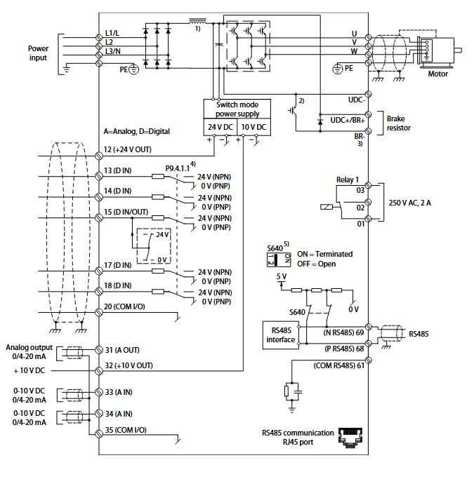
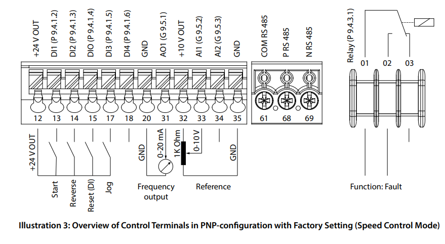
Wiring Details
Below image show terminal details:
Faults & Alarms
Search from below list for iC2 drive faults & alarms:
| Fault Code | Cause & Solution |
|---|---|
| WARNING 2 W2 Live Zero Error | Cause: This warning or fault only appears if programmed in P 9.5.6.2 Live Zero Timeout Function. The signal on 1 of the analog inputs is less than 50% of the minimum value programmed for that input. Broken wiring or a faulty device sending the signal can cause this condition. Troubleshooting: – Check connections on all the analog input terminals. Control card terminals 33 and 34 for signals, terminal 35 common. – Check that the drive programming and switch settings match the analog signal type. – Perform an input terminal signal test. |
| FAULT 2 F2 Live Zero Error | Cause: This warning or fault only appears if programmed in P 9.5.6.2 Live Zero Timeout Function. The signal on 1 of the analog inputs is less than 50% of the minimum value programmed for that input. Broken wiring or a faulty device sending the signal can cause this condition. Troubleshooting: – Check connections on all the analog input terminals. Control card terminals 33 and 34 for signals, terminal 35 common. – Check that the drive programming and switch settings match the analog signal type. – Perform an input terminal signal test. |
| Warning/ fault 3 No Motor | Cause: No motor has been connected to the output of the drive. |
| WARNING 4 Mains Phase Loss | Cause: A phase is missing on the supply side, or the mains voltage imbalance is too high. This message also appears for a fault in the input rectifier. Options are programmed in P 1.3.1 Mains Imbalance Function. Troubleshooting: – Check the supply voltage and supply currents to the drive. |
| FAULT 4 Mains Phase Loss | Cause: A phase is missing on the supply side, or the mains voltage imbalance is too high. This message also appears for a fault in the input rectifier. Options are programmed in P 1.3.1 Mains Imbalance Function. Troubleshooting: – Check the supply voltage and supply currents to the drive. |
| WARNING 7 DC Overvoltage | Cause: If the DC-link voltage exceeds the limit, the drive trips after a time. Troubleshooting: – Extend the ramp time. – Change the ramp type. |
| FAULT 7 DC Overvoltage | Cause: If the DC-link voltage exceeds the limit, the drive trips after a time. Troubleshooting: – Extend the ramp time. – Change the ramp type. |
| WARNING 8 DC Under Voltage | Cause: If the DC-link voltage (DC) drops below the undervoltage limit, the drive trips after a fixed time delay. The time delay varies with unit size. Troubleshooting: – Check that the supply voltage matches the drive voltage. – Perform the input voltage test. – Perform the soft charge circuit test. |
| FAULT 8 DC Under Voltage | Cause: If the DC-link voltage (DC) drops below the undervoltage limit, the drive trips after a fixed time delay. The time delay varies with unit size. Troubleshooting: – Check that the supply voltage matches the drive voltage. – Perform the input voltage test. – Perform the soft charge circuit test. |
| WARNING 9 Inverter Overload | Cause: The drive is about to cut out because of an overload (too high current for too long). The counter for electronic, thermal inverter protection issues a warning at 90% and trips at 100%, while giving a FAULT. The drive cannot be reset until the counter is below 0%. – The fault occurs when the drive has run with more than 100% overload for too long. Troubleshooting: – Compare the output current shown on the control panel with the drive rated current. – Compare the output current shown on the control panel with measured motor current. – Show the thermal drive load on the control panel and monitor the value. When running above the drive continuous current rating, the counter increases. When running below the drive continuous current rating, the counter decreases. |
| FAULT 9 Inverter Overload | Cause: The drive is about to cut out because of an overload (too high current for too long). The counter for electronic, thermal inverter protection issues a warning at 90% and trips at 100%, while giving a FAULT. The drive cannot be reset until the counter is below 0%. – The fault occurs when the drive has run with more than 100% overload for too long. Troubleshooting: – Compare the output current shown on the control panel with the drive rated current. – Compare the output current shown on the control panel with measured motor current. – Show the thermal drive load on the control panel and monitor the value. When running above the drive continuous current rating, the counter increases. When running below the drive continuous current rating, the counter decreases. |
| WARNING 10 Motor Overload Temperature | Cause: According to the electronic thermal protection (ETR), the motor is too hot. Select whether the drive issues a warning or an alarm when the counter reaches 100% in P 4.6.7 Motor Thermal Protection. The fault occurs when the motor runs with more than 100% overload for too long. Troubleshooting: – Check if the motor is overheating. Check if the motor is mechanically overloaded. – Check that the motor current set in P 4.2.2.3 Nominal Current is correct. – Ensure that the motor data in P 4.2.2.1 Nominal Power to P 4.2.2.5 Nominal Speed is set correctly. – Running AMA in P 4.2.1.3 AMA Mode tunes the drive to the motor more accurately and reduces thermal loading. |
| FAULT 10 Motor Overload Temperature | Cause: According to the electronic thermal protection (ETR), the motor is too hot. Select whether the drive issues a warning or an alarm when the counter reaches 100% in P 4.6.7 Motor Thermal Protection. The fault occurs when the motor runs with more than 100% overload for too long. Troubleshooting: – Check if the motor is overheating. Check if the motor is mechanically overloaded. – Check that the motor current set in P 4.2.2.3 Nominal Current is correct. – Ensure that the motor data in P 4.2.2.1 Nominal Power to P 4.2.2.5 Nominal Speed is set correctly. – Running AMA in P 4.2.1.3 AMA Mode tunes the drive to the motor more accurately and reduces thermal loading. |
| WARNING 11 Motor Thermistor Overtemp | Cause: Check whether the thermistor is disconnected. Select whether the drive issues a warning or an fault in P 4.6.7 Motor Thermal Protection. Troubleshooting: – Check for motor overheating. – Check if the motor is mechanically overloaded. – When using terminal 33 or 34, check that the thermistor is connected correctly between either terminal 33 or 34 (analog voltage input) and terminal 32 (+10 V supply). Also check that the terminal switch for 33 or 34 is set for voltage. Check that P 4.6.8 Thermistor Resource selects terminal 33 or 34. – When using terminal 13, 14, or 18 (digital inputs), check that the thermistor is connected correctly between the digital input terminal used (digital input PNP only) and terminal 32. Select the terminal to use in P 4.6.8 Thermistor Resource. |
| FAULT 11 Motor Thermistor Overtemp | Cause: Check whether the thermistor is disconnected. Select whether the drive issues a warning or an fault in P 4.6.7 Motor Thermal Protection. Troubleshooting: – Check for motor overheating. – Check if the motor is mechanically overloaded. – When using terminal 33 or 34, check that the thermistor is connected correctly between either terminal 33 or 34 (analog voltage input) and terminal 32 (+10 V supply). Also check that the terminal switch for 33 or 34 is set for voltage. Check that P 4.6.8 Thermistor Resource selects terminal 33 or 34. – When using terminal 13, 14, or 18 (digital inputs), check that the thermistor is connected correctly between the digital input terminal used (digital input PNP only) and terminal 32. Select the terminal to use in P 4.6.8 Thermistor Resource. |
| WARNING 12 Torque Limit | Cause: The torque has exceeded the value in P 5.10.1 Motor Torque Limit or the value in P 5.10.2 Regenerative Torque Limit. P 5.10.6 Trip Delay at Torque Limit can change this warning from a warning-only condition to a warning followed by an fault. Troubleshooting: – If the motor torque limit is exceeded during ramp-up, extend the ramp-up time. – If the generator torque limit is exceeded during ramp-down time, extend the ramp-down time. – If torque limit occurs while running, increase the torque limit. Make sure that the system can operate safely at a higher torque. – Check the application for excessive current draw on the motor. |
| FAULT 12 Torque Limit | Cause: The torque has exceeded the value in P 5.10.1 Motor Torque Limit or the value in P 5.10.2 Regenerative Torque Limit. P 5.10.6 Trip Delay at Torque Limit can change this warning from a warning-only condition to a warning followed by an fault. Troubleshooting: – If the motor torque limit is exceeded during ramp-up, extend the ramp-up time. – If the generator torque limit is exceeded during ramp-down time, extend the ramp-down time. – If torque limit occurs while running, increase the torque limit. Make sure that the system can operate safely at a higher torque. – Check the application for excessive current draw on the motor. |
| WARNING 13 Overcurrent | Cause: The inverter peak current limit (approximately 200% of the rated current) is exceeded. The warning lasts about 5 s, then the drive trips and issues an fault. Shock loading or fast acceleration with high-inertia loads can cause this fault. Troubleshooting: – Remove power and check if the motor shaft can be turned. – Check that the motor size matches the drive. – Check P 4.2.2.1 Nominal Power to P 4.2.2.5 Nominal Speed for correct motor data. |
| FAULT 13 Overcurrent | Cause: The inverter peak current limit (approximately 200% of the rated current) is exceeded. The warning lasts about 5 s, then the drive trips and issues an fault. Shock loading or fast acceleration with high-inertia loads can cause this fault. Troubleshooting: – Remove power and check if the motor shaft can be turned. – Check that the motor size matches the drive. – Check P 4.2.2.1 Nominal Power to P 4.2.2.5 Nominal Speed for correct motor data. |
| FAULT 14 Earth (Ground) Fault | Cause: There is a discharge from the output phases to ground, either in the cable between the drive and the motor or in the motor itself. Troubleshooting: – Turn off the drive and remove the ground fault. – Measure the resistance to ground the motor cables and the motor with a megohmmeter to check for ground faults in the motor. |
| FAULT 16 Short Circuit | Cause: There is short-circuiting in the motor or motor wiring. Troubleshooting : – Remove the power to the drive and repair the short circuit. |
| WARNING 17 Control Word Timeout | Cause: There is no communication to the drive. The warning is only active when P 5.2.16 Watchdog Response is NOT set to [0] Off. If P 5.2.16 Watchdog Response is set to [5] Stop and trip, a warning appears, and the drive ramps down to a stop and shows an fault. Troubleshooting: – Check the connections on the serial communication cable. – Increase P 5.2.17 Watchdog Delay. – Check the operation of the communication equipment. – Verify that proper EMC installation was performed. |
| FAULT 17 Control Word Timeout | Cause: There is no communication to the drive. The warning is only active when P 5.2.16 Watchdog Response is NOT set to [0] Off. If P 5.2.16 Watchdog Response is set to [5] Stop and trip, a warning appears, and the drive ramps down to a stop and shows an fault. Troubleshooting: – Check the connections on the serial communication cable. – Increase P 5.2.17 Watchdog Delay. – Check the operation of the communication equipment. – Verify that proper EMC installation was performed. |
| FAULT 18 Start Falied | Cause: The speed cannot exceed the value set in P 5.6.7 Start Max Speed [Hz] during start within the start time which is set in P 5.6.8 Start Max Time to Trip. The fault may be caused by a blocked motor. Troubleshooting: – Check if the motor is blocked. – Check if the start max speed is set higher than the working speed after ramp up. – Check if the start max time to trip is set shorter than the normal ramp up time. |
| FAULT 25 Brake Resistor Short Circuit | Cause: The brake resistor is monitored during start-up. If a short circuit occurs, the brake function is disabled and the fault appears. The drive is tripped. Troubleshooting: – Remove the power to the drive and check the connection of the brake resistor. |
| WARNING 26 Brake Resistor Power Limit | Cause: The power transmitted to the brake resistor is calculated as a mean value over the last 120 s of run time. The calculation is based on the DC-link voltage and the brake resistor value set in P 3.3.2 Brake Resistor Value. The warning is active when the dissipated braking power is higher than the value set in P 3.3.3 Brake Resistor Power Limit. The drive trips if the warning persists for 1200 s. Troubleshooting: – Decrease brake energy via lower speed or longer ramp time. |
| FAULT 26 Brake Resistor Power Limit | Cause: The power transmitted to the brake resistor is calculated as a mean value over the last 120 s of run time. The calculation is based on the DC-link voltage and the brake resistor value set in P 3.3.2 Brake Resistor Value. The warning is active when the dissipated braking power is higher than the value set in P 3.3.3 Brake Resistor Power Limit. The drive trips if the warning persists for 1200 s. Troubleshooting: – Decrease brake energy via lower speed or longer ramp time. |
| FAULT 27 Brake IGBT/Brake Chopper Short Circuited | Cause: The brake transistor is monitored during start-up. If a short circuit occurs, the brake function is disabled, and an fault is issued. The drive is tripped. Troubleshooting: – Remove the power to the drive and remove the brake resistor. |
| FAULT 28 Brake Check | Cause: The brake resistor is not connected or not working. Troubleshooting: – Check if the brake resistor is connected or it is too large for the drive. |
| FAULT 30 Motor Phase U Missing | Cause: Motor phase U between the drive and the motor is missing. Troubleshooting: – Turn off the drive and check motor phase U. |
| FAULT 31 Motor Phase V Missing | Cause: Motor phase V between the drive and the motor is missing. Troubleshooting: – Turn off the drive and check motor phase V. |
| FAULT 32 Motor Phase W Missing | Cause: Motor phase W between the drive and the motor is missing. Troubleshooting: – Turn off the drive and check motor phase W. |
| WARNING 36 Mains Failure | Cause: This warning/alarm is only active if the supply voltage to the drive is lost and P 2.3.7 Power Loss Controller Limit is not set to [0] No Function. Troubleshooting: – Check the fuses to the drive and mains supply to the unit. |
| FAULT 36 Mains Failure | Cause: This warning/alarm is only active if the supply voltage to the drive is lost and P 2.3.7 Power Loss Controller Limit is not set to [0] No Function. Troubleshooting: – Check the fuses to the drive and mains supply to the unit. |
| FAULT 38 Internal Fault | Cause: When an internal fault occurs, a code number is shown. Troubleshooting: See below Table for the causes and solutions for different internal faults. If the fault persists, contact the Danfoss supplier or service department for assistance. – 140-142: Power board EEPROM data error. Upgrade the software in the drive to the latest version. – 176: The firmware in the drive does not match the drive. Upgrade the software in the drive to the latest version. – 256: Flash ROM checksum error. Upgrade the software in the drive to the latest version. – 2304: Firmware mismatch between the control card and the power card. Upgrade the software in the drive to the latest version. – 2560: Communication error between the control card and the power card. Upgrade the software in the drive to the latest version. If the fault occurs again, check the connection between the control card and the power card. – 3840: Serial flash version error. Upgrade the software in the drive to the latest version. – 4608: Drive power size error. Upgrade the software in the drive to the latest version. If the fault occurs again, contact a Danfoss supplier. – Other: Other internal faults. Power cycle the drive. |
| WARNING 40 Overload of Digital Output Terminal 15 | Troubleshooting: – Check the load connected to terminal 15 or remove the short-circuit connection. – Check P 9.4.1.1 Digital I/O Mode and P 9.4.2.1 T 15 Mode. |
| FAULT 46 Gate Drive Voltage | Cause: The supply for the gate drive on the power card is out of range. It is generated by the switch mode supply (SMPS) on the power card. Troubleshooting: – Check for a defective power card. |
| WARNING 47 24 V Supply Low | Cause: The 24 V DC is measured on the control card. This alarm appears when the detected voltage of terminal 12 is lower than 18 V. Troubleshooting: – Check for a defective control card. |
| FAULT 47 24 V Supply Low | Cause: The 24 V DC is measured on the control card. This alarm appears when the detected voltage of terminal 12 is lower than 18 V. Troubleshooting: – Check for a defective control card. |
| FAULT 50 AMA Calibration Failed | Solution: There is an hardware or software issue in drive. Need to repair or replace drive. |
| FAULT 51 AMA Check Unom and Inom | Cause: The settings for motor voltage, motor current, and motor power are wrong. Troubleshooting: – Check settings in P 4.2.2.1 Nominal Power to P 4.2.2.5 Nominal Speed. |
| FAULT 52 AMA Low Inom | Cause: The motor current is too low. Troubleshooting: – Check the settings in parameter 1-24 Motor Current. |
| FAULT 53 AMA Big Motor | Cause: The motor is too big for the AMA to operate. |
| FAULT 54 AMA Small Motor | Cause: The motor is too small for the AMA to operate. |
| FAULT 55 AMA Parameter Range | Cause: The AMA cannot run because the paramenter values of the motor are out of the acceptable range. |
| FAULT 56 AMA Interrupt | Cause: The AMA is manually interrupted. |
| FAULT 57 AMA Timeout | Troubleshooting: – Try to restart the AMA. Repeated restarts can overheat the motor. |
| FAULT 58 AMA Internal | Solution: There is an hardware or software issue in drive. Need to repair or replace drive. |
| WARNING 59 Current Limit | Cause: The current is higher than the value in P 2.7.1 Output Current Limit %. Troubleshooting: – Ensure that the motor data in P 4.2.2.1 Nominal Power to P 4.2.2.5 Nominal Speed is set correctly. – Increase the current limit if necessary. Ensure that the system can operate safely at a higher limit. |
| FAULT 59 Current Limit | Cause: The current is higher than the value in P 2.7.1 Output Current Limit %. Troubleshooting: – Ensure that the motor data in P 4.2.2.1 Nominal Power to P 4.2.2.5 Nominal Speed is set correctly. – Increase the current limit if necessary. Ensure that the system can operate safely at a higher limit. |
| FAULT 60 External Interlock | Cause: A digital input signal indicates a fault condition external to the drive. An external interlock has commanded the drive to trip. Troubleshooting: – Clear the external fault condition. – To resume normal operation, apply 24 V DC to the terminal programmed for external interlock. – Reset the drive. |
| FAULT 63 Mechanical Brake Low | Cause: The actual motor current has not exceeded the release brake current within the start delay time window. |
| WARNING 69 Power Card Temperature | Cause: The cutout temperature of the power card has exceeded the upper limit. Troubleshooting: – Check that the ambient operating temperature is within limits. – Check the fan operation. – Check the power card. |
| FAULT 69 Power Card Temperature | Cause: The cutout temperature of the power card has exceeded the upper limit. Troubleshooting: – Check that the ambient operating temperature is within limits. – Check the fan operation. – Check the power card. |
| FAULT 80 Drive Initialized to Default Value | Cause: Parameter settings are initialized to default settings after a manual reset. Troubleshooting: – To clear the fault, reset the unit. |
| WARNING 87 Auto DC-Braking | Cause: Occurs in IT mains when the drive coasts, and the DC voltage is higher than 830 V for 400 V units and 425 V for 200 V units. The motor consumes energy on the DC link. This function can be enabled/disabled in P 2.3.13 Auto DC Braking. |
| WARNING 95 Lost Load Detected | Cause: Torque is below the torque level set for no load, indicating a lost load detection. P 5.2.9 Lost Load Function is set for alarm. Troubleshooting: – Troubleshoot the system. – Reset the drive after the fault is cleared. |
| FAULT 95 Lost Load Detected | Cause: Torque is below the torque level set for no load, indicating a lost load detection. P 5.2.9 Lost Load Function is set for alarm. Troubleshooting: – Troubleshoot the system. – Reset the drive after the fault is cleared. |
| FAULT 99 Locked Rotor | Cause: The rotor is blocked. It is only enabled for PM motor control. Troubleshooting: – Check if the motor shaft is locked. – Check if the start current triggers the current limit set in P 2.1.5 Output Current Limit %. – Check if it increases the value in P 4.6.15 Sync. Locked Rotor Detection Time [s]. |
| FAULT 126 Motor Rotating | Cause: During AMA start-up, the motor is rotating. It is only valid for PM motor. Troubleshooting: – Check if the motor is rotating before starting the AMA. |
| WARNING 127 Back EMF Too High | Cause: This warning applies to PM motors only. When the back EMF exceeds 90% x Uinvmax (overvoltage threshold) and does not drop to normal level within 5 s, this warning is reported. The warning remains until the back EMF returns to a normal level. |
| Warning fault 61 | Feedback Error |
| Err. 89 Parameter read only | Meaning: Parameters cannot be changed. |
| Err. 95 Not while running | Meaning: Parameters can only be changed when the motor is stopped. |
| Err. 96 A wrong password was entered | Meaning: Occurs when using a wrong password for changing a password-protected parameter. |