Download Links
 Download Catalog Download Catalog |
Download Manual |
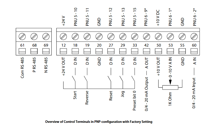
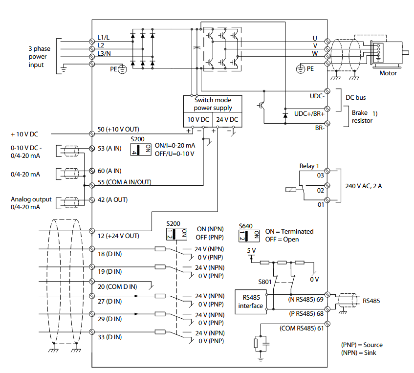
Wiring Details
Below image show terminal details:
Faults & Alarms
Search from below list for FC51 drive faults & alarms:
| Fault Code | Cause & Solution |
|---|---|
| WARNING 2 Live zero error | Cause: Signal on terminal 53 or 60 is less than 50% of value set in 6-10 Terminal 53 Low Voltage, 6-12 Terminal 53 Low Current and 6-22 Terminal 60 Low Current. |
| ALARM 2 Live zero error | Cause: Signal on terminal 53 or 60 is less than 50% of value set in 6-10 Terminal 53 Low Voltage, 6-12 Terminal 53 Low Current and 6-22 Terminal 60 Low Current. |
| WARNING 4 Mains phase loss | Cause: A phase is missing on the supply side, or the mains voltage imbalance is too high. This message also appears for a fault in the input rectifier on the frequency converter. Troubleshooting: – Check the supply voltage and supply currents to the frequency converter. The fault may be caused by mains distortions. Installing Danfoss Line Filter may rectify this problem. |
| ALARM 4 Mains phase loss | Cause: A phase is missing on the supply side, or the mains voltage imbalance is too high. This message also appears for a fault in the input rectifier on the frequency converter. Troubleshooting: – Check the supply voltage and supply currents to the frequency converter. The fault may be caused by mains distortions. Installing Danfoss Line Filter may rectify this problem. |
| WARNING 7 DC overvoltage | Cause: If the intermediate circuit voltage exceeds the limit, the frequency converter trips after a time. Troubleshooting: – Connect a brake resistor – Extend the ramp time – Change the ramp type – Activate the functions in 2-10 Brake Function – Increase 14-26 Trip Delay at Inverter Fault – The fault may be caused by mains distortions. Installing Danfoss Line Filter may rectify this problem. |
| ALARM 7 DC overvoltage | Cause: If the intermediate circuit voltage exceeds the limit, the frequency converter trips after a time. Troubleshooting: – Connect a brake resistor – Extend the ramp time – Change the ramp type – Activate the functions in 2-10 Brake Function – Increase 14-26 Trip Delay at Inverter Fault – The fault may be caused by mains distortions. Installing Danfoss Line Filter may rectify this problem. |
| WARNING 8 DC under voltage | Cause: If the intermediate circuit voltage (DC link) drops below the under voltage limit, the frequency converter checks if a 24 V DC backup supply is connected. If no 24 V DC backup supply is connected, the frequency converter trips after a fixed time delay. The time delay varies with unit size. Troubleshooting: – Check that the supply voltage matches the frequency converter voltage. – Perform input voltage test. – Perform soft charge circuit test. |
| ALARM 8 DC under voltage | Cause: If the intermediate circuit voltage (DC link) drops below the under voltage limit, the frequency converter checks if a 24 V DC backup supply is connected. If no 24 V DC backup supply is connected, the frequency converter trips after a fixed time delay. The time delay varies with unit size. Troubleshooting: – Check that the supply voltage matches the frequency converter voltage. – Perform input voltage test. – Perform soft charge circuit test. |
| WARNING 9 Inverter overload | Cause: The frequency converter is about to cut out because of an overload (too high current for too long). The counter for electronic, thermal inverter protection issues a warning at 98% and trips at 100%, while giving an alarm. The frequency converter cannot be reset until the counter is below 90%. – The fault is that the frequency converter has run with more than 100% overload for too long. Troubleshooting: – Compare the output current shown on the LCP with the frequency converter rated current. – Compare the output current shown on the LCP with measured motor current. – Display the Thermal Drive Load on the LCP and monitor the value. When running above the frequency converter continuous current rating, the counter increases. When running below the frequency converter continuous current rating, the counter decreases. |
| ALARM 9 Inverter overload | Cause: The frequency converter is about to cut out because of an overload (too high current for too long). The counter for electronic, thermal inverter protection issues a warning at 98% and trips at 100%, while giving an alarm. The frequency converter cannot be reset until the counter is below 90%. – The fault is that the frequency converter has run with more than 100% overload for too long. Troubleshooting: – Compare the output current shown on the LCP with the frequency converter rated current. – Compare the output current shown on the LCP with measured motor current. – Display the Thermal Drive Load on the LCP and monitor the value. When running above the frequency converter continuous current rating, the counter increases. When running below the frequency converter continuous current rating, the counter decreases. |
| WARNING 10 Motor overload temperature | Cause: According to the electronic thermal protection (ETR), the motor is too hot. Select whether the frequency converter gives a warning or an alarm when the counter reaches 100% in 1-90 Motor Thermal Protection. The fault occurs when the motor is overloaded by more than 100% for too long. Troubleshooting: – Check for motor overheating. – Check if the motor is mechanically overloaded – Check that the motor current set in 1-24 Motor Current is correct. – Ensure that Motor data in parameters 1-20 through 1-25 are set correctly. – Running AMT in 1-29 Automatic Motor Tuning (AMT). The inverter peak current limit (approx. 200% of the rated current) is exceeded. The warning will last approx. 8-12 s, then the frequency converter trips and issues an alarm. Turn off the frequency converter and check if the motor shaft can be turned and if the motor sizematches the frequency converter. If extended mechanical brake control is selected, trip can be reset externally. may tune the frequency converter to the motor more accurately and reduce thermal loading. |
| ALARM 10 Motor overload temperature | Cause: According to the electronic thermal protection (ETR), the motor is too hot. Select whether the frequency converter gives a warning or an alarm when the counter reaches 100% in 1-90 Motor Thermal Protection. The fault occurs when the motor is overloaded by more than 100% for too long. Troubleshooting: – Check for motor overheating. – Check if the motor is mechanically overloaded – Check that the motor current set in 1-24 Motor Current is correct. – Ensure that Motor data in parameters 1-20 through 1-25 are set correctly. – Running AMT in 1-29 Automatic Motor Tuning (AMT). The inverter peak current limit (approx. 200% of the rated current) is exceeded. The warning will last approx. 8-12 s, then the frequency converter trips and issues an alarm. Turn off the frequency converter and check if the motor shaft can be turned and if the motor sizematches the frequency converter. If extended mechanical brake control is selected, trip can be reset externally. may tune the frequency converter to the motor more accurately and reduce thermal loading. |
| WARNING 11 Motor thermistor over temp | Cause: The thermistor might be disconnected. Select whether the frequency converter gives a warning or an alarm in 1-90 Motor Thermal Protection. Troubleshooting: – Check for motor overheating. – Check if the motor is mechanically overloaded. |
| ALARM 11 Motor thermistor over temp | Cause: The thermistor might be disconnected. Select whether the frequency converter gives a warning or an alarm in 1-90 Motor Thermal Protection. Troubleshooting: – Check for motor overheating. – Check if the motor is mechanically overloaded. |
| WARNING 13 Over current | Cause: The inverter peak current limit (approx. 200% of the rated current) is exceeded. The warning will last approx. 8-12 s, then the frequency converter trips and issues an alarm. Turn off the frequency converter and check if the motor shaft can be turned and if the motor size matches the frequency converter. If extended mechanical brake control is selected, trip can be reset externally. Troubleshooting: – Remove power and check if the motor shaft can be turned. – Check that the motor size matches the frequency converter. – Check parameters 1-20 through 1-25. for correct motor data. |
| ALARM 13 Over current | Cause: The inverter peak current limit (approx. 200% of the rated current) is exceeded. The warning will last approx. 8-12 s, then the frequency converter trips and issues an alarm. Turn off the frequency converter and check if the motor shaft can be turned and if the motor size matches the frequency converter. If extended mechanical brake control is selected, trip can be reset externally. Troubleshooting: – Remove power and check if the motor shaft can be turned. – Check that the motor size matches the frequency converter. – Check parameters 1-20 through 1-25. for correct motor data. |
| ALARM 14 Earth (ground) fault | Cause: There is current from the output phases to earth, either in the cable between the frequency converter and the motor or in the motor itself. Troubleshooting: – Remove power to the frequency converter and repair the earth fault. – Check for earth faults in the motor by measuring the resistance to ground of the motor leads and the motor with a megohmmeter. |
| ALARM 16 Short circuit | Cause: There is short-circuiting in the motor or motor wiring. Solution: Remove power to the frequency converter and repair the short circuit. |
| WARNING 17 Control word timeout | Cause: There is no communication to the frequency converter. The warning is only active when 8-04 Control Word Timeout Function is NOT set to OFF. – If 8-04 Control Word Timeout Function is set to Stop and Trip, a warning appears and the frequency converter ramps down until it trips, while giving an alarm. 8-03 Control Timeout Time could possibly be increased Troubleshooting: – Check connections on the serial communication cable. – Increase 8-03 Control Word Timeout Time – Check the operation of the communication equipment. – Verify a proper installation based on EMC requirements. |
| ALARM 17 Control word timeout | Cause: There is no communication to the frequency converter. The warning is only active when 8-04 Control Word Timeout Function is NOT set to OFF. – If 8-04 Control Word Timeout Function is set to Stop and Trip, a warning appears and the frequency converter ramps down until it trips, while giving an alarm. 8-03 Control Timeout Time could possibly be increased Troubleshooting: – Check connections on the serial communication cable. – Increase 8-03 Control Word Timeout Time – Check the operation of the communication equipment. – Verify a proper installation based on EMC requirements. |
| WARNING 25 Brake resistor short circuit | Cause: The brake resistor is monitored during operation. If a short circuit occurs, the brake function is disabled and the warning appears. The frequency converter is still operational but without the brake function. Solution: Remove power to the frequency converter and replace the brake resistor (see 2-15 Brake Check). |
| WARNING 27 Brake chopper fault | Cause: The brake transistor is monitored during operation and if a short circuit occurs, the brake function is disabled and a warning is issued. The frequency converter is still operational but, since the brake transistor has short- circuited, substantial power is transmitted to the brake resistor, even if it is inactive. Solution: Remove power to the frequency converter and remove the brake resistor then check. |
| ALARM 27, Brake chopper fault | Cause: The brake transistor is monitored during operation and if a short circuit occurs, the brake function is disabled and a warning is issued. The frequency converter is still operational but, since the brake transistor has short- circuited, substantial power is transmitted to the brake resistor, even if it is inactive. Solution: Remove power to the frequency converter and remove the brake resistor then check. |
| WARNING 28 Brake check failed | Cause: The brake resistor is not connected or not working. |
| ALARM 28 Brake check failed | Cause: The brake resistor is not connected or not working. |
| ALARM 29 Heatsink temp | Cause: The maximum temperature of the heatsink has been exceeded. The temperature fault will not reset until the temperature falls below a defined heatsink temperature. – The trip and reset points are different based on the frequency converter power size. Troubleshooting: – Check for the following conditions. – Ambient temperature too high. – Motor cable too long. – Incorrect airflow clearance above and below the frequency converter. – Blocked airflow around the frequency converter. – Damaged heatsink fan. – Dirty heatsink. |
| ALARM 30 Motor phase U missing | Cause: Motor phase U between the frequency converter and the motor is missing. Solution: Remove power from the frequency converter and check motor phase U. |
| ALARM 31 Motor phase V missing | Cause: Motor phase V between the frequency converter and the motor is missing. Solution: Remove power from the frequency converter and check motor phase V. |
| ALARM 32 Motor phase W missing | Cause: Motor phase W between the frequency converter and the motor is missing. Solution: Remove power from the frequency converter and check motor phase W. |
| ALARM 38 Internal fault | Cause: Internal fault. Troubleshooting: – Cycle power – Check that the option is properly installed – Check for loose or missing wiring – There is an hardware or software issue in drive. Need to repair or replace drive. |
| WARNING 47 24 V supply low | Cause: The 24 V DC is measured on the control card. The external 24 V DC backup power supply may be overloaded. Solution: There is an hardware or software issue in drive. Need to repair or replace drive. |
| ALARM 51 AMT check Unom and Inom | Cause: The settings for motor voltage, motor current, and motor power are wrong. Solution: Check the settings in parameters 1-20 to 1-25. |
| ALARM 55 AMA parameter out of range | Cause: The parameter values of the motor are outside of the acceptable range. AMA does not run. |
| ALARM 63 Mechanical brake low | Cause: The actual motor current has not exceeded the “release brake” current within the “Start delay” time window. |
| ALARM 80 Drive initialised to default value | Cause: Parameter settings are initialised to default settings after a manual reset. Solution: Reset the unit to clear the alarm. |
| ALARM 84 | Cause: The connection between drive and LCP is lost Try to reassemble the LCP gently. |
| ALARM 85 Button disabled | Solution: See parameter group 0-4* LCP |
| ALARM 86 Copy fail | Cause: An error occurred while copying from frequency converter to LCP or vice versa. |
| ALARM 87 LCP data invalid | Cause: Occurs when copying from LCP if the LCP contains erroneous data – or if no data was uploaded to the LCP. |
| ALARM 88 LCP data not compatible | Cause: Occurs when copying from LCP if data are moved between frequency converters with major differences in software versions. |
| WARNING 89 Parameter read only | Cause: Occurs when trying to write to a read-only parameter. |
| ALARM 90 Parameter database busy | Cause: LCP and RS-485 connection are trying to update parameters simultaneously. |
| ALARM 91 Parameter value is not valid in this mode | Cause: Occurs when trying to write an illegal value to a parameter. |
| ALARM 92 Parameter value exceeds the min/max limits | Cause: Occurs when trying to set a value outside the range. Parameter can only be changed when the motor is stopped. Err. A wrong password was entered, occurs when using a wrong password for changing a password- protected parameter. |
| Warning 12 Torque limit | Cause: Torque Limit. Troubleshooting: – If the motor torque limit is exceeded during ramp-up, extend the ramp-up time. – If the generator torque limit is exceeded during ramp-down time, extend the ramp-down time. – If torque limit occurs while running, increase the torque limit. Make sure that the system can operate safely at a higher torque. – Check the application for excessive current draw on the motor. |
| FAULT 52 AMA Low Inom | Cause: The motor current is too low. Troubleshooting: – Check the settings in parameter Motor Current. |
| FAULT 53 AMA Big Motor | Cause: The motor is too big for the AMA to operate. |
| FAULT 54 AMA Small Motor | Cause: The motor is too small for the AMA to operate. |