Download Links
 Download Catalog Download Catalog |
Download Manual |
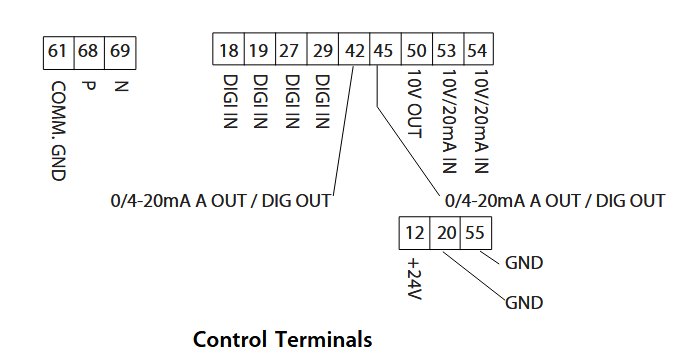
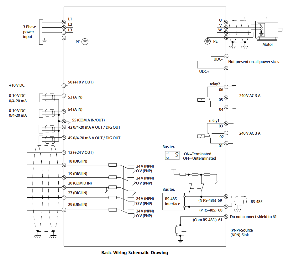
Wiring Details
Below image show terminal details:
Faults & Alarms
Search from below list for FC101 drive faults & alarms:
| Fault Code | Cause & Solution |
|---|---|
| WARNING 2 Live zero error | Cause: This warning or alarm only appears if parameter 6-01 Live Zero Timeout Function is configured. The signal on 1 of the analog inputs is less than 50% of the minimum value programmed for that input. This condition can be caused by broken wiring or a faulty device sending the signal. Troubleshooting: – Check connections on all the analog input terminals. Control card terminals 53 and 54 for signals, terminal 55 common. – Check that the frequency converter programming matches the analog signal type. |
| ALARM 2 Live zero error | Cause: This warning or alarm only appears if parameter 6-01 Live Zero Timeout Function is configured. The signal on 1 of the analog inputs is less than 50% of the minimum value programmed for that input. This condition can be caused by broken wiring or a faulty device sending the signal. Troubleshooting: – Check connections on all the analog input terminals. Control card terminals 53 and 54 for signals, terminal 55 common. – Check that the frequency converter programming matches the analog signal type. |
| WARNING 3 No motor | Cause: No motor is connected to the output of the frequency converter. Solution: – Check the cable connection between the frequency converter and the motor. |
| ALARM 3 No motor | Cause: No motor is connected to the output of the frequency converter. Solution: – Check the cable connection between the frequency converter and the motor. |
| WARNING 4 Mains phase loss | Cause: A phase is missing on the supply side, or the mains voltage imbalance is too high. This message also appears for a fault in the input rectifier on the frequency converter. Options are programmed at parameter 14-12 Function at Mains Imbalance. Troubleshooting: – Check the supply voltage and supply currents to the frequency converter. |
| ALARM 4 Mains phase loss | Cause: A phase is missing on the supply side, or the mains voltage imbalance is too high. This message also appears for a fault in the input rectifier on the frequency converter. Options are programmed at parameter 14-12 Function at Mains Imbalance. Troubleshooting: – Check the supply voltage and supply currents to the frequency converter. |
| WARNING 7 DC overvoltage | Cause: If the DC-link voltage exceeds the limit, the frequency converter trips after a time. Troubleshooting: – Extend the ramp time. – Activate functions in parameter 2-10 Brake Function. – Activate overvoltage control in parameter 2-17 Over-voltage Control. |
| ALARM 7 DC overvoltage | Cause: If the DC-link voltage exceeds the limit, the frequency converter trips after a time. Troubleshooting: – Extend the ramp time. – Activate functions in parameter 2-10 Brake Function. – Activate overvoltage control in parameter 2-17 Over-voltage Control. |
| WARNING 8 DC under voltage | Cause: If the DC-link voltage (DC) drops below the under voltage limit, the frequency converter trips after a fixed time delay. The time delay varies with unit size. Troubleshooting: – Check that the supply voltage matches the frequency converter voltage. – Perform an input voltage test. |
| ALARM 8 DC under voltage | Cause: If the DC-link voltage (DC) drops below the under voltage limit, the frequency converter trips after a fixed time delay. The time delay varies with unit size. Troubleshooting: – Check that the supply voltage matches the frequency converter voltage. – Perform an input voltage test. |
| WARNING 9 Inverter overload | Cause: The frequency converter is about to cut out because of an overload (too high current for too long). The counter for electronic, thermal inverter protection issues a warning at 90% and trips at 100%, while issuing an alarm. The frequency converter cannot be reset until the counter is below 90%. – The fault is that the frequency converter is overloaded by more than 100% for too long. Troubleshooting: – Compare the output current shown on the LCP with the frequency converter rated current. – Compare the output current shown on the LCP with measured motor current. – Display the thermal drive load on the LCP and monitor the value. When running above the frequency converter continuous current rating, the counter increases. When running below the frequency converter continuous current rating, the counter decreases. |
| ALARM 9 Inverter overload | Cause: The frequency converter is about to cut out because of an overload (too high current for too long). The counter for electronic, thermal inverter protection issues a warning at 90% and trips at 100%, while issuing an alarm. The frequency converter cannot be reset until the counter is below 90%. – The fault is that the frequency converter is overloaded by more than 100% for too long. Troubleshooting: – Compare the output current shown on the LCP with the frequency converter rated current. – Compare the output current shown on the LCP with measured motor current. – Display the thermal drive load on the LCP and monitor the value. When running above the frequency converter continuous current rating, the counter increases. When running below the frequency converter continuous current rating, the counter decreases. |
| WARNING 10 Motor overload temperature | Cause: According to the electronic thermal protection (ETR), the motor is too hot. Select whether the frequency converter issues a warning or an alarm when the counter reaches 100% in parameter 1-90 Motor Thermal Protection. The fault is that the motor is overloaded by more than 100% for too long. Troubleshooting: – Check if the motor is overheating. – Check if the motor is mechanically overloaded – Ensure that the motor parameter 1-24 Motor Current is set correctly. – Ensure motor data in parameters 1-20 through 1-25 are set correctly. – Run AMA in parameter 1-29 Automatic Motor Adaption (AMA). |
| ALARM 10 Motor overload temperature | Cause: According to the electronic thermal protection (ETR), the motor is too hot. Select whether the frequency converter issues a warning or an alarm when the counter reaches 100% in parameter 1-90 Motor Thermal Protection. The fault is that the motor is overloaded by more than 100% for too long. Troubleshooting: – Check if the motor is overheating. – Check if the motor is mechanically overloaded – Ensure that the motor parameter 1-24 Motor Current is set correctly. – Ensure motor data in parameters 1-20 through 1-25 are set correctly. – Run AMA in parameter 1-29 Automatic Motor Adaption (AMA). |
| WARNING 11 Motor thermistor over temp | Cause: The thermistor or the thermistor connection is disconnected. Select whether the frequency converter issues a warning or an alarm in parameter 1-90 Motor Thermal Protection. Troubleshooting: – Check if the motor is overheating. – Check if the motor is mechanically overloaded. – Ensure that the thermistor is connected correctly. – If using a thermal switch or thermistor, ensure that the programming of parameter 1-93 Thermistor Source matches sensor wiring. |
| ALARM 11 Motor thermistor over temp | Cause: The thermistor or the thermistor connection is disconnected. Select whether the frequency converter issues a warning or an alarm in parameter 1-90 Motor Thermal Protection. Troubleshooting: – Check if the motor is overheating. – Check if the motor is mechanically overloaded. – Ensure that the thermistor is connected correctly. – If using a thermal switch or thermistor, ensure that the programming of parameter 1-93 Thermistor Source matches sensor wiring. |
| WARNING 13 Over current | Cause: The inverter peak current limit is exceeded. The warning lasts about 1.5 s, then the frequency converter trips and issues an alarm. Troubleshooting: – This fault may be caused by shock loading or fast acceleration with high inertia loads. – Turn off the frequency converter. Check if the motor shaft can be turned. – Check that the motor size matches the frequency converter. – Incorrect motor data in parameters 1-20 through 1-25. |
| ALARM 13 Over current | Cause: The inverter peak current limit is exceeded. The warning lasts about 1.5 s, then the frequency converter trips and issues an alarm. Troubleshooting: – This fault may be caused by shock loading or fast acceleration with high inertia loads. – Turn off the frequency converter. Check if the motor shaft can be turned. – Check that the motor size matches the frequency converter. – Incorrect motor data in parameters 1-20 through 1-25. |
| ALARM 14 Earth (ground) fault | Cause: There is current from the output phases to earth, either in the cable between the frequency converter and the motor or in the motor itself. Troubleshooting: – Remove power to the frequency converter and repair the earth fault. – Check for earth faults in the motor by measuring the resistance to ground of the motor leads and the motor with a megohmmeter. |
| ALARM 16 Short circuit | Cause: There is short-circuiting in the motor or motor wiring. Solution: Remove power to the frequency converter and repair the short circuit. |
| WARNING 17 Control word timeout | Cause: There is no communication to the frequency converter. The warning is only active when 8-04 Control Word Timeout Function is NOT set to OFF. – If 8-04 Control Word Timeout Function is set to Stop and Trip, a warning appears and the frequency converter ramps down until it trips, while giving an alarm. 8-03 Control Timeout Time could possibly be increased Troubleshooting: – Check connections on the serial communication cable. – Increase 8-03 Control Word Timeout Time – Check the operation of the communication equipment. – Verify a proper installation based on EMC requirements. |
| ALARM 17 Control word timeout | Cause: There is no communication to the frequency converter. The warning is only active when 8-04 Control Word Timeout Function is NOT set to OFF. – If 8-04 Control Word Timeout Function is set to Stop and Trip, a warning appears and the frequency converter ramps down until it trips, while giving an alarm. 8-03 Control Timeout Time could possibly be increased Troubleshooting: – Check connections on the serial communication cable. – Increase 8-03 Control Word Timeout Time – Check the operation of the communication equipment. – Verify a proper installation based on EMC requirements. |
| WARNING 24 Fan fault | Cause: The fan warning function is an extra protection function that checks whether the fan is running/mounted. The fan warning can be disabled in parameter 14-53 Fan Monitor ([0] Disabled). Troubleshooting: – Check fan resistance. |
| ALARM 24 Fan fault | Cause: The fan warning function is an extra protection function that checks whether the fan is running/mounted. The fan warning can be disabled in parameter 14-53 Fan Monitor ([0] Disabled). Troubleshooting: – Check fan resistance. |
| ALARM 30 Motor phase U missing | Cause: Motor phase U between the frequency converter and the motor is missing. Solution: Remove power from the frequency converter and check motor phase U. |
| ALARM 31 Motor phase V missing | Cause: Motor phase V between the frequency converter and the motor is missing. Solution: Remove power from the frequency converter and check motor phase V. |
| ALARM 32 Motor phase W missing | Cause: Motor phase W between the frequency converter and the motor is missing. Solution: Remove power from the frequency converter and check motor phase W. |
| ALARM 38 Internal fault | Cause: Internal fault. Troubleshooting: – Cycle power – Check that the option is properly installed – Check for loose or missing wiring – There is an hardware or software issue in drive. Need to repair or replace drive. |
| ALARM 44 Earth fault II | Cause: There is a discharge from the output phases to ground, either in the cable between the frequency converter and the motor or in the motor itself. Troubleshooting: – Turn off the frequency converter and remove the ground fault. – Measure the resistance to ground of the motor cables and the motor with a megohmmeter to check for a ground fault in the motor. |
| ALARM 46 Gate drive voltage low | Cause: The supply on the power card is out of range. There are 3 supplies generated by the switch mode power supply (SMPS) on the power card: 24 V, 5 V, and ±18 V. Troubleshooting: – Check the power card. |
| ALARM 47 24 V supply low | Cause: The 24 V DC is measured on the control card.It occurs when the detected voltage on terminal 12 is lower than 18 V. Check the control card and the load connected. |
| ALARM 51 AMA check Unom and Inom | Cause: The setting of motor voltage, motor current, and motor power is presumably wrong. Solution: Check the settings. |
| ALARM 52 AMA low Inom | Cause: The motor current is too low. – Check the settings. |
| ALARM 53 AMA motor too big | Cause: The motor is too large for the AMA to be performed. |
| ALARM 54 AMA motor too small | Cause: The motor is too small for the AMA to be performed. |
| ALARM 55 AMA Parameter out of range | Cause: The parameter values found from the motor are outside the acceptable range. |
| ALARM 56 AMA interrupted by user | Cause: The AMA is interrupted. |
| ALARM 57 AMA timeout | Cause: Try to start the AMA again a number of times, until the AMA is performed. Note that repeated runs may heat the motor to a level where the resistance Rs and Rr are increased. In most cases, this is not critical. |
| ALARM 58 AMA internal fault | Cause: AMA internal fault. Solution: There is an hardware or software issue in drive. Need to repair or replace drive. |
| WARNING 59 Current limit | Cause: The current is higher than the value in parameter 4-18 Current Limit. |
| ALARM 60 External interlock | Cause: External interlock has been activated. To resume normal operation, apply 24 V DC to the terminal programmed for external Interlock and reset the frequency converter (via serial communication, digital I/O, or by pressing [Reset]). |
| ALARM 69 Power card temperature | Cause: The temperature on the power card is either too high or too low. Troubleshooting: – Ensure that the ambient operating temperature is within the limits. – Check if the filters are clogged. – Check the fan operation. – Check the power card. |
| ALARM 70 Illegal power section configuration | Cause: The control card and power card are incompatible. Contact your supplier with the type code of the unit from the nameplate and the part numbers of the cards to check compatibility. |
| ALARM 80 Drive initialised to default value | Cause: Parameter settings are initialised to default settings after a manual reset. |
| ALARM 95 Broken belt | Cause: Torque is below the torque level set for no load, indicating a broken belt. Parameter 22-60 Broken Belt Function is set for alarm. Troubleshooting: – Troubleshoot the system and reset the frequency converter after clearing the fault. |
| ALARM 126 Motor Rotating | Cause: During AMA start-up, the motor is rotating. It is only valid for PM motor. Troubleshooting: – Check if the motor is rotating before starting the AMA. |
| WARNING 127 Back EMF too High | Cause: This warning applies to PM motors only. When the back EMF exceeds 90% x Uinvmax (overvoltage threshold) and does not drop to a normal level within 5 s, this warning is reported. The warning remains until the back EMF returns to a normal level. |
| WARNING 200 Fire Mode | Cause: Fire mode has been activated. |
| WARNING 202 Fire Mode Limits Exceeded | Cause: Fire Mode has suppressed one or more warranty-voiding alarms. |
| ALARM 250 New Spare Part | Cause: The power or switch mode supply has been exchanged. |
| ALARM 251 New Type Code | Cause: The frequency converter has a new type code. |
| Err 84 LCP comm. | Cause: Lost Communication between the LCP and the frequency converter is lost. |
| Err 85 Button disabled | Cause: The LCP key is disabled. One of the LCP keys has been disabled in parameter group 0-4* LCP Keypad. |
| Err 86 LCP copy failed | Cause: Data copy failure. This error occurs when data is copied from frequency converter to LCP, or from LCP to frequency converter (parameter 0-50 LCP Copy). |
| Err 88 Data not compatible | Cause: LCP data incompatible. This error occurs when data is being copied from LCP to frequency converter (parameter 0-50 LCP Copy). The typical reason is that data is moved between frequency converter and LCP that have major software differences. |
| Err 89 Read only | Cause: Parameter read only. An operation is issued via LCP to write a value to a parameter that is read-only. |
| Err 90 Database busy | Cause: The parameter database of the frequency converter is busy. |
| Err 91 Parameter invalid | Cause: The parameter value that is input via the LCP is invalid. |
| Err 92 Exceeds limits | Cause: The parameter value that is input via the LCP exceeds limits. |
| Err 93 Motor is running | Cause: The LCP copy operation cannot be performed when the frequency converter is running. |
| Err 95 Not while running | Cause: The parameter cannot be changed while the frequency converter is running. |
| Err 96 Password rejected | Cause: The password that is input via the LCP is incorrect. |
| Alarm 50 AMA calibration failed | Cause: AMA calibration failed |
| Warning 66 Heat sink temperature low | Cause: Heat sink temperature low. |
| Warning 79 Illegal PS config | Cause: Illegal PS config. |
| alarm 79 Illegal PS config | Cause: Illegal PS config. |
| ALARM 84 | Cause: LCP error |
| warning 87 Auto DC brake | Cause: Auto DC brake. |
| WARNING 200 Fire Mode | Cause: Fire mode has been activated. |