Download Links
 Download Catalog Download Catalog |
Download Manual |
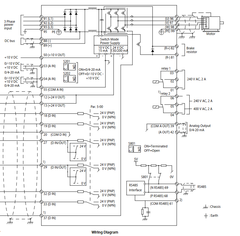
Wiring Details
Below image show terminal details:
Faults & Alarms
Search from below list for FC302 drive faults & alarms:
| Fault Code | Cause & Solution |
|---|---|
| Warning 1 10 Volts Low | Cause: The control card voltage is less than 10 V from terminal 50. Remove some of the load from terminal 50, as the 10 V supply is overloaded. Maximum 15 mA or minimum 590 Ω. – A short circuit in a connected potentiometer or incorrect wiring of the potentiometer can cause this condition. Troubleshooting: – Remove the wiring from terminal 50. – If the warning clears, the problem is with the wiring. If the warning does not clear, replace the control card. |
| WARNING 2 Live zero error | Cause: This warning or alarm only appears if programmed in parameter 6-01 Live Zero Timeout Function. The signal on 1 of the analog inputs is less than 50% of the minimum value programmed for that input. Broken wiring or faulty device sending the signal can cause this condition. Troubleshooting: 1. Check connections on all the analog input terminals. a. Control card terminals 53 and 54 for signals, terminal 55 common. b. VLT® General Purpose I/O MCB 101 terminals 11 and 12 for signals, terminal 10 common. c. VLT® Analog I/O Option MCB 109 terminals 1, 3, and 5 for signals, terminals 2, 4, and 6 common. Check that the drive programming and switch settings match the analog signal type. 2. Perform the input terminal signal test. |
| ALARM 2 Live zero error | Cause: This warning or alarm only appears if programmed in parameter 6-01 Live Zero Timeout Function. The signal on 1 of the analog inputs is less than 50% of the minimum value programmed for that input. Broken wiring or faulty device sending the signal can cause this condition. Troubleshooting: 1. Check connections on all the analog input terminals. a. Control card terminals 53 and 54 for signals, terminal 55 common. b. VLT® General Purpose I/O MCB 101 terminals 11 and 12 for signals, terminal 10 common. c. VLT® Analog I/O Option MCB 109 terminals 1, 3, and 5 for signals, terminals 2, 4, and 6 common. Check that the drive programming and switch settings match the analog signal type. 2. Perform the input terminal signal test. |
| WARNING 3 No motor | Cause: No motor is connected to the output of the frequency converter. Solution: – Check the cable connection between the frequency converter and the motor. |
| ALARM 3 No motor | Cause: No motor is connected to the output of the frequency converter. Solution: – Check the cable connection between the frequency converter and the motor. |
| WARNING 4 Mains phase loss | Cause: A phase is missing on the supply side, or the mains voltage imbalance is too high. This message also appears for a fault in the input rectifier on the frequency converter. Options are programmed at parameter 14-12 Function at Mains Imbalance. Troubleshooting: – Check the supply voltage and supply currents to the frequency converter. |
| ALARM 4 Mains phase loss | Cause: A phase is missing on the supply side, or the mains voltage imbalance is too high. This message also appears for a fault in the input rectifier on the frequency converter. Options are programmed at parameter 14-12 Function at Mains Imbalance. Troubleshooting: – Check the supply voltage and supply currents to the frequency converter. |
| Warning 5 DC Link Voltage High | Cause: The DC-link voltage (DC) is higher than the high-voltage warning limit. The limit depends on the drive voltage rating. The unit is still active. |
| WARNING 6 DC Link Voltage Low | Cause: The DC-link voltage (DC) is lower than the low-voltage warning limit. The limit depends on the drive voltage rating. The unit is still active. |
| WARNING 7 DC overvoltage | Cause: If the DC-link voltage exceeds the limit, the frequency converter trips after a time. Troubleshooting: – Extend the ramp time. – Change the ramp type. – Activate the functions in parameter 2-10 Brake Function. – Increase parameter 14-26 Trip Delay at Inverter Fault. – If the alarm/warning occurs during a power sag, use kinetic back-up (parameter 14-10 Mains Failure). – Connect a brake resistor. |
| ALARM 7 DC overvoltage | Cause: If the DC-link voltage exceeds the limit, the frequency converter trips after a time. Troubleshooting: – Extend the ramp time. – Change the ramp type. – Activate the functions in parameter 2-10 Brake Function. – Increase parameter 14-26 Trip Delay at Inverter Fault. – If the alarm/warning occurs during a power sag, use kinetic back-up (parameter 14-10 Mains Failure). – Connect a brake resistor. |
| WARNING 8 DC under voltage | Cause: If the DC-link voltage drops below the undervoltage limit, the drive checks for 24 V DC back-up supply. If no 24 V DC back-up supply is connected, the drive trips after a fixed time delay. The time delay varies with unit size. Troubleshooting: – Check that the supply voltage matches the drive voltage. – Perform an input voltage test. – Perform a soft-charge circuit test. |
| ALARM 8 DC under voltage | Cause: If the DC-link voltage drops below the undervoltage limit, the drive checks for 24 V DC back-up supply. If no 24 V DC back-up supply is connected, the drive trips after a fixed time delay. The time delay varies with unit size. Troubleshooting: – Check that the supply voltage matches the drive voltage. – Perform an input voltage test. – Perform a soft-charge circuit test. |
| WARNING 9 Inverter overload | Cause: The drive has run with more than 100% overload for too long and is about to cut out. The counter for electronic thermal inverter protection issues a warning at 98% and trips at 100% with an alarm. The drive cannot be reset until the counter is below 90%. Troubleshooting: – Compare the output current shown on the LCP with the drive rated current. – Compare the output current shown on the LCP with the measured motor current. – Show the thermal drive load on the LCP and monitor the value. – When running above the drive continuous current rating, the counter increases. – When running below the drive continuous current rating, the counter decreases. |
| ALARM 9 Inverter overload | Cause: The drive has run with more than 100% overload for too long and is about to cut out. The counter for electronic thermal inverter protection issues a warning at 98% and trips at 100% with an alarm. The drive cannot be reset until the counter is below 90%. Troubleshooting: – Compare the output current shown on the LCP with the drive rated current. – Compare the output current shown on the LCP with the measured motor current. – Show the thermal drive load on the LCP and monitor the value. – When running above the drive continuous current rating, the counter increases. – When running below the drive continuous current rating, the counter decreases. |
| WARNING 10 Motor Overload Temperature | Cause: According to the electronic thermal protection (ETR), the motor is too hot. Select whether the drive issues a warning or an alarm when the counter reaches 100% in parameter 1-90 Motor Thermal Protection. The fault occurs when the motor runs with more than 100% overload for too long. Troubleshooting: – Check for motor overheating. – Check if the motor is mechanically overloaded. – Check that the motor current set in parameter 1-24 Motor Current is correct. – Ensure that the motor data in parameter 1-20 to parameter 1-25 is set correctly. – Running AMA in parameter 1-29 Automatic Motor Adaptation (AMA) tunes the drive to the motor more accurately and reduces thermal loading. |
| ALARM 10 Motor Overload Temperature | Cause: According to the electronic thermal protection (ETR), the motor is too hot. Select whether the drive issues a warning or an alarm when the counter reaches 100% in parameter 1-90 Motor Thermal Protection. The fault occurs when the motor runs with more than 100% overload for too long. Troubleshooting: – Check for motor overheating. – Check if the motor is mechanically overloaded. – Check that the motor current set in parameter 1-24 Motor Current is correct. – Ensure that the motor data in parameter 1-20 to parameter 1-25 is set correctly. – Running AMA in parameter 1-29 Automatic Motor Adaptation (AMA) tunes the drive to the motor more accurately and reduces thermal loading. |
| WARNING 11 Motor thermistor over temp | Cause: The motor thermistor indicates that the motor temperature is too high. Troubleshooting: – Check for motor overheating. – Check that the thermistor is securely connected. – Check whether the motor is mechanically overloaded. – When using terminal 53 or 54: – Check that the thermistor is connected correctly between either terminal 53 or 54 (analog voltage input) and terminal 50 (+10 V supply). – Check that the terminal switch for 53 and 54 is set for voltage. – Check that parameter 1-93 Thermistor Resource selects 53 or 54. – When using terminal 18, 19, 31, 32, or 33 (digital inputs): – Check that the thermistor is connected correctly between the digital input terminal used (digital input PNP only) and terminal 50. – Select the terminal to use in parameter 1-93 Thermistor Resource. |
| ALARM 11 Motor thermistor over temp | Cause: The motor thermistor indicates that the motor temperature is too high. Troubleshooting: – Check for motor overheating. – Check that the thermistor is securely connected. – Check whether the motor is mechanically overloaded. – When using terminal 53 or 54: – Check that the thermistor is connected correctly between either terminal 53 or 54 (analog voltage input) and terminal 50 (+10 V supply). – Check that the terminal switch for 53 and 54 is set for voltage. – Check that parameter 1-93 Thermistor Resource selects 53 or 54. – When using terminal 18, 19, 31, 32, or 33 (digital inputs): – Check that the thermistor is connected correctly between the digital input terminal used (digital input PNP only) and terminal 50. – Select the terminal to use in parameter 1-93 Thermistor Resource. |
| WARNING 12 Torque Limit | Cause: The torque has exceeded the value in parameter 4-16 Torque Limit Motor Mode or the value in parameter 4-17 Torque Limit Generator Mode. Parameter 14-25 Trip Delay at Torque Limit can change this warning from a warning-only condition to a warning followed by an alarm. Troubleshooting: – If the motor torque limit is exceeded during ramp-up, extend the ramp-up time. – If the generator torque limit is exceeded during ramp-down, extend the ramp-down time. – If torque limit occurs while running, increase the torque limit. Make sure that the system can operate safely at a higher torque. – Check the application for excessive current draw on the motor. |
| ALARM 12 Torque Limit | Cause: The torque has exceeded the value in parameter 4-16 Torque Limit Motor Mode or the value in parameter 4-17 Torque Limit Generator Mode. Parameter 14-25 Trip Delay at Torque Limit can change this warning from a warning-only condition to a warning followed by an alarm. Troubleshooting: – If the motor torque limit is exceeded during ramp-up, extend the ramp-up time. – If the generator torque limit is exceeded during ramp-down, extend the ramp-down time. – If torque limit occurs while running, increase the torque limit. Make sure that the system can operate safely at a higher torque. – Check the application for excessive current draw on the motor. |
| WARNING 13 Over current | Cause: The inverter peak current limit (approximately 200% of the rated current) is exceeded. The warning lasts about 1.5 s, then the drive trips and issues an alarm. Shock loading or quick acceleration with high-inertia loads can cause this fault. If the acceleration during ramp-up is quick, the fault can also appear after kinetic backup. If extended mechanical brake control is selected, a trip can be reset externally. Troubleshooting: – Remove power and check if the motor shaft can be turned. – Check that the motor size matches the drive. – Check that the motor data is correct in parameters 1-20 to 1-25. |
| ALARM 13 Over current | Cause: The inverter peak current limit (approximately 200% of the rated current) is exceeded. The warning lasts about 1.5 s, then the drive trips and issues an alarm. Shock loading or quick acceleration with high-inertia loads can cause this fault. If the acceleration during ramp-up is quick, the fault can also appear after kinetic backup. If extended mechanical brake control is selected, a trip can be reset externally. Troubleshooting: – Remove power and check if the motor shaft can be turned. – Check that the motor size matches the drive. – Check that the motor data is correct in parameters 1-20 to 1-25. |
| ALARM 14 Earth (ground) fault | Cause: There is current from the output phase to ground, either in the cable between the drive and the motor, or in the motor itself. The current sensors detect the ground fault by measuring current going out from the drive and current going into the drive from the motor. Ground fault is issued if the deviation of the 2 currents is too large. The current going out of the drive must be the same as the current going into the drive. Troubleshooting: – Remove power to the drive and repair the ground fault. – Check for ground faults in the motor by measuring the resistance to ground of the motor cables and the motor with a megohmmeter. – Reset any potential individual offset in the 3 current sensors in the drive. Perform a manual initialization or perform a complete AMA. This method is most relevant after changing the power card. |
| Alarm 15 Hardware Mismatch | Cause: A fitted option is not operational with the present control card hardware or software. Troubleshooting: Record the values of the following parameters and contact . – a. Parameter 15-40 FC Type – b. Parameter 15-41 Power Section – c. Parameter 15-42 Voltage – d. Parameter 15-43 Software Version – e. Parameter 15-45 Actual Typecode String – f. Parameter 15-49 SW ID Control Card – g. Parameter 15-50 SW ID Power Card – h. Parameter 15-60 Option Mounted – i. Parameter 15-61 Option SW Version (for each option slot). |
| ALARM 16 Short circuit | Cause: There is short-circuiting in the motor or motor wiring. Solution: Remove power to the frequency converter and repair the short circuit. |
| WARNING 17 Control word timeout | Cause: There is no communication to the drive. The warning is only active when parameter 8-04 Control Word Timeout Function is NOT set to [0] Off. – If parameter 8-04 Control Word Timeout Function is set to [5] Stop and Trip, a warning appears. The drive then ramps down to stop and issues an alarm. Troubleshooting: – Check the connections on the serial communication cable. – Increase parameter 8-03 Control Word Timeout Time. – Check the operation of the communication equipment. – Verify that the installation adheres to the EMC requirements. |
| ALARM 17 Control word timeout | Cause: There is no communication to the drive. The warning is only active when parameter 8-04 Control Word Timeout Function is NOT set to [0] Off. – If parameter 8-04 Control Word Timeout Function is set to [5] Stop and Trip, a warning appears. The drive then ramps down to stop and issues an alarm. Troubleshooting: – Check the connections on the serial communication cable. – Increase parameter 8-03 Control Word Timeout Time. – Check the operation of the communication equipment. – Verify that the installation adheres to the EMC requirements. |
| WARNING 20 Temp. Input Error | Cause: The temperature detected by VLT® Sensor Input Option MCB 114 exceeds the limit. – This warning/alarm is only active when [5] Stop and trip is selected in parameter 35-06 Temperature Sensor Alarm Function. Troubleshooting: 1. Check the settings of the following parameters: – a. Parameter group 35-1* Temp. Input X48/4 – b. Parameter group 35-2* Temp. Input X48/7 – c. Parameter group 35-3* Temp. Input X48/10 2. Check the feedback temperature from the following parameters: – a. Parameter 18-37 Temp. Input X48/4 – b. Parameter 18-38 Temp. Input X48/7Programming Guide | VLT® HVAC Drive FC 102 |
| ALARM 20 Temp. Input Error | Cause: The temperature detected by VLT® Sensor Input Option MCB 114 exceeds the limit. – This warning/alarm is only active when [5] Stop and trip is selected in parameter 35-06 Temperature Sensor Alarm Function. Troubleshooting: 1. Check the settings of the following parameters: – a. Parameter group 35-1* Temp. Input X48/4 – b. Parameter group 35-2* Temp. Input X48/7 – c. Parameter group 35-3* Temp. Input X48/10 2. Check the feedback temperature from the following parameters: – a. Parameter 18-37 Temp. Input X48/4 – b. Parameter 18-38 Temp. Input X48/7 |
| WARNING 21 Parameter Error | Cause: The parameter is out of range. The parameter number is shown in the display. Troubleshooting: – Set the affected parameter to a valid value. |
| ALARM 21 Parameter Error | Cause: The parameter is out of range. The parameter number is shown in the display. Troubleshooting: – Set the affected parameter to a valid value. |
| Warning 22 Hoist Mechanical Brake | Cause: The value of this warning/alarm shows the type of warning/alarm. – 0 = The torque reference was not reached before timeout (parameter 2-27 Torque Ramp Up Time. – 1 = Expected brake feedback was not received before timeout (parameter 2-23 Activate Brake Delay, parameter 2-25 Brake Release Time. |
| Alarm 22 Hoist Mechanical Brake | Cause: The value of this warning/alarm shows the type of warning/alarm. – 0 = The torque reference was not reached before timeout (parameter 2-27 Torque Ramp Up Time. – 1 = Expected brake feedback was not received before timeout (parameter 2-23 Activate Brake Delay, parameter 2-25 Brake Release Time. |
| Warning 23 Internal Fan Fault | Cause: The fan warning function is a protective function that checks if the fan is running/mounted. The fan warning can be disabled in parameter 14-53 Fan Monitor by selecting [0] Disabled. For drives with DC fans, a feedback sensor is mounted in the fan. If the fan is commanded to run and there is no feedback from the sensor, this warning appears. For drives with AC fans, the voltage to the fan is monitored. Troubleshooting: – Cycle for proper fan operation. – Cycle power to the drive and check that the fan operates briefly at start-up. – Check the sensors on the control card. |
| Warning 24 External Fan Fault | Cause: The fan warning function is a protective function that checks if the fan is running/mounted. The fan warning can be disabled in parameter 14-53 Fan Monitor by selecting [0] Disabled. For drives with DC fans, a feedback sensor is mounted in the fan. If the fan is commanded to run and there is no feedback from the sensor, this warning appears. For drives with AC fans, the voltage to the fan is monitored. Troubleshooting: – Check for proper fan operation. – Cycle power to the drive and check that the fan operates briefly at start-up. – Check the sensors on the heat sink. |
| WARNING 25 Brake Resistor Short Circuit | Cause: The brake resistor is monitored during operation. If a short circuit occurs, the brake function is disabled, and the warning appears. The drive is still operational, but without the brake function. Troubleshooting: – Remove the power to the drive and replace the brake resistor (refer to parameter 2-15 Brake Check. |
| WARNING 26 Brake Resistor Power Limit | Cause: The power transmitted to the brake resistor is calculated as an average value over the last 120 s of run time. The calculation is based on the DC-link voltage and the brake resistor value set in parameter 2-16 Brake Max. Current. The warning is active when the dissipated braking power is higher than 90% of the brake resistor power. If [2] Trip is selected in parameter 2-13 Brake Power Monitoring, the drive trips when the dissipated braking power reached 100%. Troubleshooting: – Decrease brake energy via lower speed or longer ramp time. |
| ALARM 26 Brake Resistor Power Limit | Cause: The power transmitted to the brake resistor is calculated as an average value over the last 120 s of run time. The calculation is based on the DC-link voltage and the brake resistor value set in parameter 2-16 Brake Max. Current. The warning is active when the dissipated braking power is higher than 90% of the brake resistor power. If [2] Trip is selected in parameter 2-13 Brake Power Monitoring, the drive trips when the dissipated braking power reached 100%. Troubleshooting: – Decrease brake energy via lower speed or longer ramp time. |
| WARNING 27 Brake Chopper Fault | Cause: The brake transistor is monitored during operation. If a short circuit occurs, the brake function is disabled, and a warning is issued. The drive is still operational, but since the brake transistor has short-circuited, substantial power is transmitted to the brake resistor, even if it is inactive. Troubleshooting: – Remove the power to the drive, and remove the brake resistor. |
| ALARM 27 Brake Chopper Fault | Cause: The brake transistor is monitored during operation. If a short circuit occurs, the brake function is disabled, and a warning is issued. The drive is still operational, but since the brake transistor has short-circuited, substantial power is transmitted to the brake resistor, even if it is inactive. Troubleshooting: – Remove the power to the drive, and remove the brake resistor. |
| WARNING 28 Brake Check Failed | Cause: The brake resistor is not connected or not working. Troubleshooting: – Check parameter 2-15 Brake Check. |
| ALARM 28 Brake Check Failed | Cause: The brake resistor is not connected or not working. Troubleshooting: – Check parameter 2-15 Brake Check. |
| ALARM 29 Heat Sink Temp | Cause: The maximum temperature of the heat sink is exceeded. The temperature fault is not reset until the temperature drops below a defined heat sink temperature. The trip and reset points are different, based on the drive power size. Troubleshooting: Check for the following conditions: – The ambient temperature is too high. – The motor cables are too long. – Incorrect airflow clearance above and below the drive. – Blocked airflow around the drive. – Damaged heat sink fan. – Dirty heat sink. |
| ALARM 30 Motor phase U missing | Cause: Motor phase U between the frequency converter and the motor is missing. Solution: Remove power from the frequency converter and check motor phase U. |
| ALARM 31 Motor phase V missing | Cause: Motor phase V between the frequency converter and the motor is missing. Solution: Remove power from the frequency converter and check motor phase V. |
| ALARM 32 Motor phase W missing | Cause: Motor phase W between the frequency converter and the motor is missing. Solution: Remove power from the frequency converter and check motor phase W. |
| ALARM 33 Inrush Fault | Cause: Too many power-ups have occurred within a short time period. Troubleshooting: – Let the unit cool to operating temperature. – Check potential DC-link fault to ground. |
| WARNING 34 Fieldbus Fault | Cause: The fieldbus on the communication option card is not working. Troubleshooting: – Check the fieldbus communication option card. |
| ALARM 34 Fieldbus Fault | Cause: The fieldbus on the communication option card is not working. Troubleshooting: – Check the fieldbus communication option card. |
| Warning 35 Option Fault | Cause: An option alarm is received. The alarm is option-specific. The most likely cause is a power-up or a communication fault. Troubleshooting: – There is an hardware or software issue in drive. Need to repair or replace drive. |
| ALARM 35 Option Fault | Cause: An option alarm is received. The alarm is option-specific. The most likely cause is a power-up or a communication fault. Troubleshooting: – There is an hardware or software issue in drive. Need to repair or replace drive. |
| WARNING 36 Mains Failure | Cause: This warning/alarm is only active if the supply voltage to the drive is lost and parameter 14-10 Mains Failure is not set to [0] No function. Troubleshooting: – Check the fuses to the drive and mains supply to the unit. |
| Alarm 36 Mains Failure | Cause: This warning/alarm is only active if the supply voltage to the drive is lost and parameter 14-10 Mains Failure is not set to [0] No function. Troubleshooting: – Check the fuses to the drive and mains supply to the unit. |
| ALARM 37 Phase Imbalance | Cause: There is a current imbalance between the power units. |
| ALARM 38 Internal Fault | Cause: When an internal fault occurs, a code number defined in below table. Troubleshooting: – Cycle power. – Check that the option is properly installed. – Check for loose or missing wiring. – It may be necessary to contact the Danfoss supplier or service department. Note the code number for further troubleshooting directions. – 0: The serial port cannot be initialized. Contact the Danfoss supplier or Danfoss service department. – 256–258: The power EEPROM data is defective or too old. Replace the power card. – 512–519: Internal fault. Contact the Danfoss supplier or Danfoss service department. – 783: Parameter value outside of minimum/maximum limits. – 1024–1284: Internal fault. Contact the Danfoss supplier or Danfoss service department. – 1299: The option software in slot A is too old. – 1300: The option software in slot B is too old. – 1302: The option software in slot C1 is too old. – 1315: The option software in slot A is not supported/allowed. – 1316: The option software in slot B is not supported/ allowed. – 1318: The option software in slot C1 is not supported/ allowed. – 1379–2819: Internal fault. Contact the Danfoss supplier or Danfoss service department. – 1792: Hardware reset of digital signal processor. – 1793: Motor-derived parameters not transferred correctly to the digital signal processor. – 1794: Power data not transferred correctly at power-up to the digital signal processor. – 1795: The digital signal processor has received too many unknown SPI telegrams. The AC drive also uses this fault code if – the: MCO does not power up correctly. This situation can occur due to poor EMC protection or improper grounding. – 1796: RAM copy error. – 2561: Replace the control card. – 2820: LCP stack overflow. – 2821: Serial port overflow. – 2822: USB port overflow. – 3072–5122: Parameter value is outside its limits. – 5123: Option in slot A: Hardware incompatible with the control board hardware. – 5124: Option in slot B: Hardware incompatible with the control board hardware. – 5125: Option in slot C0: Hardware incompatible with the control board hardware. – 5126: Option in slot C1: Hardware incompatible with the control board hardware. – 5376– 6231: Internal fault. Contact the Danfoss supplier or Danfoss service department. |
| ALARM 39 Heat Sink Sensor | Cause: There is no feedback from the heat sink temperature sensor. The signal from the IGBT thermal sensor is not available on the power card. Troubleshooting: – Check the ribbon cable between the power card and the gate drive card. – Check for a defective power card. – Check for a defective gate drive card. |
| WARNING 40 Overload T27 | Troubleshooting: – Check the load connected to terminal 27 or remove the short-circuit connection. – Check parameter 5-00 Digital I/O Mode and parameter 5-01 Terminal 27 Mode. |
| WARNING 41 Overload T29 | Troubleshooting: – Check the load connected to terminal 29 or remove the short-circuit connection. – Check parameter 5-00 Digital I/O Mode and parameter 5-02 Terminal 29 Mode. |
| WARNING 42 Ovrld X30/6-7 | Troubleshooting, X30/6: – Check the load connected to the terminal or remove the short-circuit connection. – Check parameter 5-32 Term X30/6 Digi Out (MCB 101)(VLT® General Purpose I/O MCB 101). Troubleshooting, X30/7: – Check the load connected to the terminal or remove the short-circuit connection. – Check parameter 5-33 Term X30/7 Digi Out (MCB 101)(VLT® General Purpose I/O MCB 101). |
| WARNING 43 Ext. Supply | Cause: VLT® Extended Relay Option MCB 113 is mounted without 24 V DC. Select 1 of the options in the troubleshooting list. Troubleshooting: – Connect a 24 V DC external supply. – Specify that no external supply is used via parameter 14-80 Option Supplied by External 24VDC set to [0] No. A change in parameter 14-80 Option Supplied by External 24VDC requires a power cycle. |
| ALARM 45 Earth (Ground) Fault 2 | Cause: A ground fault has occurred. Troubleshooting: – Check for proper grounding and loose connections. – Check for proper wire size. – Check the motor cables for short circuits or leakage currents. |
| ALARM 46 Power Card Supply | Cause: The supply on the power card is out of range. Another reason can be a defective heat sink fan. There are 3 supplies generated by the switch mode supply (SMPS) on the power card: – 24 V. – 5 V. – ±18 V. When powered with VLT® 24 V DC Supply MCB 107, only 24 V and 5 V supplies are monitored. When powered with 3-phase mains voltage, all 3 supplies are monitored. Troubleshooting: – Check for a defective power card. – Check for a defective control card. – Check for a defective option card. – If 24 V DC is used, verify proper supply power. – Check for a defective heat sink fan. |
| ALARM 47 24 V Supply Low | Cause: The supply on the power card is out of range. There are 3 supplies generated by the switch mode supply (SMPS) on the power card: – 44 V – 5 V – ±18 V Troubleshooting: – Check for a defective power card. |
| ALARM 48 1.8 V Supply Low | Cause: The 1.8 V DC supply used on the control card is outside of the allowed limits. The supply is measured on the control card. Troubleshooting: – Check for a defective control card. – If an option is installed, check for overvoltage. |
| WARNING 49 SPEED LIMIT | Cause: The warning is shown when the speed is outside of the specified range in parameter 4-11 Motor Speed Low Limit [RPM] and parameter 4-13 Motor Speed High Limit [RPM]. When the speed is below the specified limit in parameter 1-86 Trip Speed Low [RPM] (except when starting or stopping), the drive trips. |
| FAULT 50 AMA Calibration Failed | Solution: There is an hardware or software issue in drive. Need to repair or replace drive. |
| ALARM 51 AMA check Unom and Inom | Cause: The setting of motor voltage, motor current, and motor power is presumably wrong. Solution: Check the settings in parameter 1-20 to parameter 1-25. |
| ALARM 52 AMA low Inom | Cause: The motor current is too low. – Check the setting in parameter 1-24 Motor Current. |
| ALARM 53 AMA motor too big | Cause: The motor is too large for the AMA to be performed. Troubleshooting: – Check the settings in parameter group 1-2* Motor Data. |
| ALARM 54 AMA motor too small | Cause: The motor is too small for the AMA to be performed. Troubleshooting: – Check the settings in parameter group 1-2* Motor Data. |
| ALARM 55 AMA Parameter out of range | Cause: The parameter values found from the motor are outside the acceptable range. |
| ALARM 56 AMA interrupted by user | Cause: The AMA is interrupted. Troubleshooting – Re-run the AMA calibration. |
| ALARM 57 AMA Internal Fault | Cause: Internal fault. Troubleshooting: – Try to restart the AMA. Repeated restarts can overheat the motor. |
| ALARM 58 AMA internal fault | Cause: AMA internal fault. Solution: There is an hardware or software issue in drive. Need to repair or replace drive. |
| WARNING 59 Current limit | Cause: The current is higher than the value in parameter 4-18 Current Limit. Troubleshooting: – Ensure that the motor data in parameters 1-20 to 1-25 is set correctly. – Increase the current limit if necessary. Ensure that the system can operate safely at a higher limit. |
| ALARM 60 External interlock | Cause: A digital input signal indicates a fault condition external to the drive. Within the control compartment, the following 3 relay contacts are connected in series to 1 digital input that is used as a thermal overload relay: – KFJ.1 monitors the heat within the input power options cabinet. – KFJ.2 monitors the heat within the output filter cabinet. – KFJ.3 monitors the heat within the input filter cabinet. When the thermal switches in any of these cabinets open due to overtemperature, the drive trips on External Interlock [A60]. Troubleshooting: – Open the control compartment and check for any lights in relays KFJ.1, KFJ.2, and KFJ.3. If no lights are present, check for other external interlocks. – Clear the external fault condition. – To resume normal operation, apply 24 V DC to the terminal programmed for external interlock. – Reset the drive. |
| WARNING 61 Feedback Error | Cause: An error between calculated speed and speed measurement from feedback device. Troubleshooting: – Check the settings for warning/alarm/disabling in parameter 4-30 Motor Feedback Loss Function. – Set the tolerable error in parameter 4-31 Motor Feedback Speed Error. – Set the tolerable feedback loss time in parameter 4-32 Motor Feedback Loss Timeout. |
| ALARM 61 Feedback Error | Cause: An error between calculated speed and speed measurement from feedback device. Troubleshooting: – Check the settings for warning/alarm/disabling in parameter 4-30 Motor Feedback Loss Function. – Set the tolerable error in parameter 4-31 Motor Feedback Speed Error. – Set the tolerable feedback loss time in parameter 4-32 Motor Feedback Loss Timeout. |
| WARNING 62 Output Frequency at Maximum Limit | Cause: The output frequency has reached the value set in parameter 4-19 Max Output Frequency. Troubleshooting: – Check the application for possible causes. – Increase the output frequency limit. Be sure that the system can operate safely at a higher output frequency. – The warning clears when the output drops below the maximum limit. |
| ALARM 63 Mechanical Brake Low | Cause: The actual motor current has not exceeded the release brake current within the start delay time window. |
| WARNING 64 VOLTAGE LIMIT | Cause: The load and speed combination demands a motor voltage higher than the actual DC-link voltage. Troubleshooting: – Check if the mains input is not high enough. – Check if the output frequency is too high above motor nominal frequency. |
| WARNING 65 Control card over temperature | Cause: The cutout temperature of the control card has exceeded the upper limit. Troubleshooting: – Check that the ambient operating temperature is within the limits. – Check the fan operation. – Check the control card. |
| ALARM 65 Control card over temperature | Cause: The cutout temperature of the control card has exceeded the upper limit. Troubleshooting: – Check that the ambient operating temperature is within the limits. – Check the fan operation. – Check the control card. |
| Warning 66 Heat Sink Temperature Low | Cause: The drive is too cold to operate. This warning is based on the temperature sensor in the IGBT module. Troubleshooting: – Increase the ambient temperature of the unit. – Supply a trickle amount of current to the drive whenever the motor is stopped by setting parameter 2-00 DC Hold/Preheat Current to 5% and parameter 1-80 Function at Stop. |
| ALARM 67 Option Module Configuration Has Changed | Cause: One or more options have either been added or removed since the last power-down. Troubleshooting: – Check that the configuration change is intentional and reset the unit. |
| ALARM 68 Safe Stop Activated | Cause: The Safe Torque Off (STO) has been activated. Troubleshooting: – To resume normal operation, apply 24 V DC to terminal 37, then send a reset signal via bus, digital I/O, or by pressing [Reset]. |
| ALARM 70 Illegal FC Configuration | Cause: The control card and power card are incompatible. Troubleshooting: – To check compatibility, contact the supplier with the type code from the unit nameplate and the part numbers on the cards |
| ALARM 71 PTC 1 Safe Stop | Cause: Because the motor is too warm, the VLT® PTC Thermistor Card MCB 112 activated Safe Torque Off (STO). Troubleshooting Once the motor temperature reaches an acceptable level, and the digital input from MCB 112 is deactivated, perform 1 of the following: – Send a reset signal via bus or digital I/O. – Press [Reset]. |
| ALARM 72 Dangerous Failure | Cause: Safe Torque Off (STO) with trip lock. An unexpected combination of STO commands has occurred. Troubleshooting: – VLT® PTC Thermistor Card MCB 112 enables X44/10, but STO is not enabled. – MCB 112 is the only device using STO (specified via [4] PTC 1 alarm or [5] PTC 12 warning in parameter 5-19 Terminal 37 Safe Stop). STO is activated, but X44/10 is not. |
| WARNING 73 Safe Stop Auto Restart | Cause: STO is activated. Troubleshooting: – With automatic restart enabled, the motor can start when the fault is cleared. |
| ALARM 74 PTC Thermistor | Cause: The PTC is not working. Alarm is related to VLTÆ PTC Thermistor Card MCB 112. |
| ALARM 75 Illegal Profile Sel | Cause: There was an attempt to write the parameter value while the motor was running. Troubleshooting: – Stop the motor before writing the MCO profile to parameter 8-10 Control Word Profile. |
| WARNING 76 Power Unit Setup | Cause: The required number of power units does not match the detected number of active power units. Troubleshooting: – When replacing a drive module, this warning can occur if the power-specific data in the module power card does not match the rest of the drive. Confirm that the spare part and its power card are the correct code number. |
| WARNING 77 Reduced Power Mode | Cause: The drive is operating in reduced power mode (less than allowed number of inverter sections). The warning is generated on power cycle when the drive is set to run with fewer inverters and remains on. |
| ALARM 78 Tracking Error | Cause: The difference between setpoint value and actual value exceeds the value in parameter 4-35 Tracking Error. Troubleshooting: – Disable the function or select an alarm/warning in parameter 4-34 Tracking Error Function. – Investigate the mechanics around the load and motor. Check feedback connections from motor encoder to drive. – Select motor feedback function in parameter 4-30 Motor Feedback Loss Function. – Adjust the tracking error band in parameter 4-35 Tracking Error and parameter 4-37 Tracking Error Ramping. |
| ALARM 79 Illegal Power Section Configuration | Cause: The scaling card has an incorrect code number or is not installed. The MK102 connector on the power card could not be installed. |
| ALARM 80 Drive Initialized to Default Value | Cause: Parameter settings are initialized to default settings after a manual reset. Troubleshooting: – To clear the alarm, reset the unit. |
| ALARM 81 CSIV Corrupt | Cause: The CSIV file has syntax errors. |
| ALARM 82 CSIV Parameter Error | Cause: CSIV failed to initialize a parameter. |
| ALARM 83 Illegal Option Combination | Cause: The mounted options are incompatible. |
| ALARM 84 No Safety Option | Cause: The safety option was removed without applying a general reset. Troubleshooting: – Reconnect the safety option. |
| ALARM 85 Dang Fail PB | Cause: PROFIBUS/PROFIsafe error. |
| ALARM 88 Option Detection | Cause: A change in the option layout is detected. Parameter 14-89 Option Detection is set to [0] Frozen configuration and the option layout has been changed. Troubleshooting: – To apply the change, enable option layout changes in parameter 14-89 Option Detection. – Alternatively, restore the correct option configuration. |
| WARNING 89 Mechanical Brake Sliding | Cause: The hoist brake monitor detects a motor speed exceeding 10 RPM. |
| WARNING 90 Feedback Monitor | Cause: A feedback fault is detected. Solution: Check the connection to the encoder/resolver option and, if necessary, replace the VLTÆ Encoder Input MCB 102 or VLTÆ Resolver Input MCB 103. |
| ALARM 91 Analog Input 54 Wrong Settings | Troubleshooting: – Set switch S202 in position OFF (voltage input) when a KTY sensor is connected to analog input terminal 54. |
| ALARM 99 Locked Rotor | Cause: The rotor is blocked. Troubleshooting: – Check if the motor shaft is locked. – Check if the start current triggers the current limit set in parameter 4-18 Current Limit. – Check if it increases the value in parameter 30-23 Locked Rotor Detection Time [s]. |
| WARNING 104 Mixing Fan Fault | Cause: The fan is not operating. The fan monitor checks that the fan is spinning at power-up or whenever the mixing fan is turned on. The mixing fan fault can be configured as a warning or an alarm in parameter 14-53 Fan Monitor. Troubleshooting: – Cycle power to the drive to determine if the warning/alarm returns. |
| ALARM 104 Mixing Fan Fault | Cause: The fan is not operating. The fan monitor checks that the fan is spinning at power-up or whenever the mixing fan is turned on. The mixing fan fault can be configured as a warning or an alarm in parameter 14-53 Fan Monitor. Troubleshooting: – Cycle power to the drive to determine if the warning/alarm returns. |
| WARNING 122 Mot. Rotat. Unexp. | Cause: The drive performs a function that requires the motor to be at a standstill, for example, DC hold for PM motors. |
| ALARM 122, Mot. Rotat. Unexp. | Cause: The drive performs a function that requires the motor to be at a standstill, for example, DC hold for PM motors. |
| WARNING 163 ATEX ETR Cur.Lim. Warning | Cause: The drive has run above the characteristic curve for more than 50 s. The warning is activated at 83% and deactivated at 65% of the allowed thermal overload. |
| Alarm 164 ATEX ETR Cur.Lim. Alarm | Cause: Running above the characteristic curve for more than 60 s within a period of 600 s activated the alarm, and the drive trips. |
| WARNING 165 ATEX ETR Freq.Lim. Warning | Cause: The drive has run for more than 50 s below the allowed minimum frequency as set in parameter 1-98 ATEX ETR Interpol. Points.Freq.). |
| ALARM 166 ATEX ETR Freq.Lim. Alarm | Cause: The drive has run for more than 60 s in a period of 600 s below the allowed minimum frequency as set in parameter 1-98 ATEX ETR Interpol. Points. Freq.). |
| ALARM 244 Heat Sink Temperature | Cause: The maximum temperature of the heat sink has been exceeded. The temperature fault cannot reset until the temperature drops below the defined heat sink temperature. The trip and reset points are different, based on the power size. This alarm is equivalent to Alarm 29, Power module temp. Troubleshooting: Check for the following: – a. Ambient temperature too high. – b. Motor cables too long. – c. Incorrect airflow clearance above or below the AC drive. – d. Blocked airflow around the unit. – e. Damaged heat sink fan. – f. Dirty heat sink. |
| WARNING 251 New Typecode | Cause: The power card or other components have been replaced, and the type code has changed. Troubleshooting: – Reset the drive for normal operation. |
| ALARM 421 Temperature Fault | Cause: A fault caused by the on-board temperature sensor is detected on the fan power card. The report values identify which fan power card detected the fault. Troubleshooting: – Check the wiring. – Check the on-board temperature sensor. – Replace the fan power card. |
| ALARM 423 FPC Updating | Cause: The alarm is generated when the fan power card reports that it has an invalid PUD. The control card attempts to update the PUD. A subsequent alarm can result depending on the update. See Alarm 424, FPC Update Successul and Alarm 425, FPC Update Failure. |
| ALARM 424 FPC Update Successful | Cause: This alarm is generated when the control card has updated the fan power card PUD successfully. Troubleshooting: – Press [Reset] to stop the alarm. |
| ALARM 425 FPC Update Failure | Cause: This alarm is generated after the control card failed to update the fan power card PUD. Troubleshooting: – Check the fan power card wiring. – Replace the fan power card. |
| ALARM 426 FPC Config | Cause: The number of found fan power cards does not match the number of configured fan power cards. See parameter group 15-6* Option Ident for the number of configured fan power cards. Troubleshooting: – Check fan power card wiring. – Replace the fan power card. |
| ALARM 427 FPC Supply | Cause: Supply voltage faults (5 V, 24 V, or 48 V) on the fan power card is detected. Troubleshooting: – Check fan power card wiring. – Replace the fan power card. |
| ALARM 2 Live zero error | Cause: This warning or alarm only appears if programmed in parameter 6-01 Live Zero Timeout Function. The signal on 1 of the analog inputs is less than 50% of the minimum value programmed for that input. Broken wiring or faulty device sending the signal can cause this condition. Troubleshooting: 1. Check connections on all the analog input terminals. a. Control card terminals 53 and 54 for signals, terminal 55 common. b. VLT® General Purpose I/O MCB 101 terminals 11 and 12 for signals, terminal 10 common. c. VLT® Analog I/O Option MCB 109 terminals 1, 3, and 5 for signals, terminals 2, 4, and 6 common. Check that the drive programming and switch settings match the analog signal type. 2. Perform the input terminal signal test. |