Download Links
 Download Catalog Download Catalog |
Download Manual |
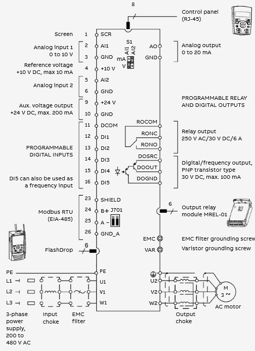
Wiring Details
Below image show terminal details:
Faults & Alarms
Search from below list for ACS310 drive faults & alarms:
| Code | Cause & Solution |
|---|---|
| A2001 OVERCURRENT | Cause: Output current limit controller is active. Solution: 1. Check motor load. 2. Check acceleration time (parameters 2202 ACCELER TIME 1 and 2205 ACCELER TIME 2). 3. Check motor and motor cable (including phasing). 4. Check ambient conditions. |
| A2002 OVERVOLTAGE | Cause: DC overvoltage controller is active. Solution: 1. Check deceleration time (parameters 2203 DECELER TIME 1 and 2206 DECELER TIME 2). 2. Check input power line for static or transient overvoltage. |
| A2003 UNDERVOLTAGE | Cause: DC undervoltage controller is active. Solution: Check input power supply. |
| A2004 DIRLOCK | Cause: Change of direction is not allowed. Solution: Check parameter 1003 DIRECTION settings. |
| A2005 IO COMM | Cause: Fieldbus communication break. Solution: 1. Check status of fieldbus communication. 2. Check fault function parameter settings. 3. Check connections. 4. Check if master can communicate. |
| A2006 AI1 LOSS | Cause: Analog input AI1 signal has fallen below limit defined by parameter 3021 AI1 FAULT LIMIT. Solution: 1. Check fault function parameter settings. 2. Check for proper analog control signal levels. 3. Check connections. |
| A2007 AI2 LOSS | Cause: Analog input AI2 signal has fallen below limit defined by parameter 3022 AI1 FAULT LIMIT. Solution: 1. Check fault function parameter settings. 2. Check for proper analog control signal levels. 3. Check connections. |
| A2008 PANEL LOSS | Cause: Control panel selected as active control location for drive has ceased communicating. Solution: 1. Check panel connection. 2. Check fault function parameters. 3. Check control panel connector. 4. Refit control panel in mounting platform. 5. If drive is in external control mode (REM) and is set to accept start/stop, direction commands or references through control panel: Check group 10 START/STOP/DIR and 11 REFERENCE SELECT settings. |
| A2009 DEVICE OVERTEMP | Cause: Drive IGBT temperature is excessive. Alarm limit is 120 °C. Solution: 1. Check ambient conditions. 2. Check air flow and fan operation. 3. Check motor power against drive power. |
| A2010 MOTOR TEMP | Cause: Motor temperature is too high (or appears to be too high) due to excessive load, insufficient motor power, inadequate cooling or incorrect start-up data. Solution: 1. Check motor ratings, load and cooling. 2. Check start-up data. 3. Check fault function parameter settings. 4. Let motor cool down. 5. Ensure proper motor cooling: Check cooling fan, clean cooling surfaces, etc. |
| A2012 MOTOR STALL | Cause: Motor is operating in stall region due to, for example, excessive load or insufficient motor power. Solution: 1. Check motor load and drive ratings. 2. Check fault function parameter settings. |
| A2013 AUTORESET | Cause: Automatic reset alarm. Solution: Check parameter group 31 AUTOMATIC RESET settings. |
| A2014 AUTOCHANGE | Cause: PFC Autochange function is active. Solution: See parameter group 81 PFC CONTROL. |
| A2015 PFC I LOCK | Cause: PFC Interlocks are active. Solution: 1. Drive cannot start • any motor (when Autochange is used) • the speed regulated motor (when Autochange is not used). 2. See parameter group 81 PFC CONTROL. |
| A2018 PID SLEEP | Cause: Sleep function has entered the sleeping mode. Solution: See parameter groups 40 PROCESS PID SET 1… 41 PROCESS PID SET 2. |
| A2021 START ENABLE 1 MISSING | Cause: No Start enable 1 signal received. Solution: 1. Check parameter 1608 START ENABLE 1 settings. 2. Check digital input connections. 3. Check fieldbus communication settings. |
| A2022 START ENABLE 2 MISSING | Cause: No Start enable 2 signal received. Solution: 1. Check parameter 1609 START ENABLE 2 settings. 2. Check digital input connections. 3. Check fieldbus communication settings. |
| A2023 EMERGENCY STOP | Cause: Drive has received emergency stop command and ramps to stop according to ramp time defined by parameter 2208 EMERG DEC TIME. Solution: 1. Check that it is safe to continue operation. 2. Return emergency stop push button to normal position. |
| A2025 FIRST START | Cause: Motor identification magnetization is on. This alarm belongs to normal start-up procedure. Solution: Wait until drive indicates that motor identification is completed. |
| A2026 INPUT PHASE LOSS | Cause: Intermediate circuit DC voltage is oscillating due to missing input power line phase or blown fuse. Alarm is generated when DC voltage ripple exceeds 14% of nominal DC voltage. Solution: 1. Check input power line fuses. 2. Check for input power supply imbalance. 3. Check fault function parameter setting. 4. This is a programmable fault function, check parameter 3016 SUPPLY PHASE |
| A2027 USER LOAD CURVE | Cause: Condition defined by 3701 USER LOAD C MODE has been valid longer than half of the time set by 3703 USER LOAD C TIME. Solution: See parameter group 37 USER LOAD CURVE. |
| A2028 START DELAY | Cause: Start delay in progress Solution: See parameter 2113 START DELAY. |
| A2030 INLET LOW | Cause: Pressure at pump/fan inlet too low Solution: 1. Check for a closed valve on the inlet side of the pump/fan. 2. Check piping for leaks. 3. See parameter group 44 PUMP PROTECTION. |
| A2031 OUTLET HIGH | Cause: Pressure at pump/fan outlet too high Solution: 1. Check piping for blocks. 2. See parameter group 44 PUMP PROTECTION. |
A2032 PIPE FILL | Cause: Pipe fill in progress. Solution: See parameters 4421…4426. |
| A2033 INLET VERY LOW | Cause: Pressure at pump/fan inlet too low. Solution: 1. Check for a closed valve on the inlet side of the pump/fan. 2. Check piping for leaks. 3. See parameter group 44 PUMP PROTECTION. |
| A2034 OUTLET VERY HIGH | Cause: Pressure at pump/fan outlet too high. Solution: 1. Check piping for blocks. 2. See parameter group 44 PUMP PROTECTION. |
| A2038 MOTOR HEATING | Cause: Motor heating is active. Solution: 1. See parameter 2115 MOT. HEATING SEL. |
| A5001 | Cause: Drive is not responding. Solution: Check panel connection. |
| A5002 | Cause: Incompatible communication profile. Solution: There is an hardware or software issue in drive, need to repaur or replace drive. |
| A5010 | Cause: Corrupted panel parameter backup file Solution: 1. Retry parameter upload. 2. Retry parameter download. |
| A5011 | Cause: Drive is controlled from another source. Solution: Change drive control to the local control mode. |
| A5012 | Cause: Direction of rotation is locked. Solution: Enable change of direction. See parameter 1003 DIRECTION. |
| A5013 | Cause: Panel control is disabled because start inhibit is active. Solution: 1. Start from the panel is not possible. Reset the emergency stop command or remove the 3-wire stop command before starting from the panel. 2. Check parameters 1001 EXT1 COMMANDS, 1002 EXT2 COMMANDS and 2109 EMERG STOP SEL. |
| A5014 | Cause: Panel control is disabled because of drive fault. Solution: Reset drive fault and retry. |
| A5015 | Cause: Panel control is disabled because the local control mode lock is active. Solution: Deactivate the local control mode lock and retry. See parameter 1606 LOCAL LOCK. |
| A5018 | Cause: Parameter default value is not found. Solution: There is an hardware or software issue in drive, need to repaur or replace drive. |
| A5019 | Cause: Writing non-zero parameter value is prohibited. Solution: Only parameter reset is allowed. |
| A5020 | Cause: Parameter or parameter group does not exist or parameter value is inconsistent. Solution: There is an hardware or software issue in drive, need to repaur or replace drive. |
| A5021 | Cause: Parameter or parameter group is hidden. Solution: There is an hardware or software issue in drive, need to repaur or replace drive. |
| A5022 | Cause: Parameter is write protected. Solution: Parameter value is read-only and cannot be changed. |
| A5023 | Cause: Parameter change is not allowed, when drive is running. Solution: Stop drive and change parameter value. |
| A5024 | Cause: Drive is executing task. Solution: Wait until task is completed. |
| A5025 | Cause: Software is being uploaded or downloaded. Solution: Wait until upload/download is complete. |
| A5026 | Cause: Value is at or below minimum limit. |
| A5027 | Cause: Value is at or above maximum limit. |
| A5028 | Cause: Invalid value |
| A5029 | Cause: Memory is not ready. Solution: Retry. |
| A5030 | Cause: Invalid request |
| A5031 | Cause: Drive is not ready for operation, for example, due to low DC voltage. Solution: Check input power supply. |
| A5032 | Cause: Parameter error. |
| A5040 | Cause: Parameter download error. Selected parameter set is not in current parameter backup file. Solution: Perform upload function before download. |
| A5041 | Cause: Parameter backup file does not fit into memory. Solution: There is an hardware or software issue in drive, need to repaur or replace drive. |
| A5042 | Cause: Parameter download error. Selected parameter set is not in current parameter backup file. Solution: Perform upload function before download. |
| A5043 | Cause: No start inhibit. |
| A5044 | Cause: Parameter backup file restoring error. Solution: 1. Check that file is compatible with drive. |
| A5050 | Cause: Parameter upload aborted. Solution: 1. Retry parameter upload. |
| A5051 | Cause: File error. Solution: There is an hardware or software issue in drive, need to repaur or replace drive. |
| A5052 | Cause: Parameter upload has failed. Solution: Retry parameter upload. |
| A5060 | Cause: Parameter download aborted. Solution: 1. Retry parameter download. |
| A5062 | Cause: Parameter download has failed. Solution: Retry parameter download. |
| A5070 | Cause: Panel backup memory write error. Solution: There is an hardware or software issue in drive, need to repaur or replace drive. |
| A5071 | Cause: Panel backup memory read error. Solution: There is an hardware or software issue in drive, need to repaur or replace drive. |
A5080 | Cause: Operation is not allowed because the drive is not in the local control mode. Solution: Switch to the local control mode. |
| A5081 | Cause: Operation is not allowed because of active fault. Solution: Check cause of fault and reset fault. |
| A5083 | Cause: Operation is not allowed because parameter lock is on. Solution: Check parameter 1602 PARAMETER LOCK setting. |
| A5084 | Cause: Operation is not allowed because drive is performing a task. Solution: Wait until task is completed and retry. |
| A5085 | Cause: Parameter download from source to destination drive has failed. Solution: 1. Check that source and destination drive types are same, ie ACS310. See the type designation label of the drive. |
| A5086 | Cause: Parameter download from source to destination drive has failed. Solution: 1. Check that source and destination drive type designations are the same. 2. See type designation labels of the drives. |
| A5087 | Cause: Parameter download from source to destination drive has failed because parameter sets are incompatible. Solution: 1. Check that source and destination drive information are same. See parameters in group 33 INFORMATION. |
| A5088 | Cause: Operation has failed because of drive memory error. Solution: There is an hardware or software issue in drive, need to repaur or replace drive. |
| A5089 | Cause: Download has failed because of CRC error. Solution: There is an hardware or software issue in drive, need to repaur or replace drive. |
| A5090 | Cause: Download has failed because of data processing error. Solution: There is an hardware or software issue in drive, need to repaur or replace drive. |
| A5091 | Cause: Operation has failed because of parameter error. Solution: There is an hardware or software issue in drive, need to repaur or replace drive. |
| A5092 | Cause: Parameter download from source to destination drive has failed because parameter sets are incompatible. Solution: 1. Check that source and destination drive information are same. See parameters in group 33 INFORMATION. |
| F0001 OVERCURRENT | Cause: Output current has exceeded trip level. Overcurrent trip limit for drive is 325% of drive nominal current. Solution: 1. Check motor load. 2. Check acceleration time (parameters 2202 ACCELER TIME 1 and 2205 ACCELER TIME 2). 3. Check motor and motor cable (including phasing). 4. Check ambient conditions. Load capacity decreases if installation site ambient temperature exceed 40 °C. |
| F0002 DC OVERVOLT | Cause: Excessive intermediate circuit DC voltage. DC overvoltage trip limit is 420 V for 200 V drives and 840 V for 400 V drives. Solutions: 1. Check that overvoltage controller is on (parameter 2005 OVERVOLT CTRL). 2. Check brake chopper and resistor (if used). DC overvoltage control must be deactivated when brake chopper and resistor are used. 3. Check deceleration time (parameters 2203 DECELER TIME 1 and 2206 DECELER TIME 2). 4. Check input power line for static or transient overvoltage. 5. Retrofit frequency converter with brake chopper and brake resistor. |
| F0003 DEV OVERTEMP | Cause: Drive IGBT temperature is excessive. Fault trip limit is 135 °C. Solution: 1. Check ambient conditions. 2. Check air flow and fan operation. 3. Check motor power against drive power. |
| F0004 SHORT CIRC | Cause: Short circuit in motor cable(s) or motor Solution: 1. Check motor and motor cable. |
| F0006 DC UNDERVOLTAGE | Cause: Intermediate circuit DC voltage is not sufficient due to missing input power line phase, blown fuse, rectifier bridge internal fault or too low input power. Solution: 1. Check that undervoltage controller is on (parameter 2006 UNDERVOLT CTRL). 2. Check input power supply and fuses. |
| F0007 AI1 LOSS | Cause: Analog input AI1 signal has fallen below limit defined by parameter 3021 AI1 FAULT LIMIT. Solution: 1. Check fault function parameter settings. 2. Check for proper analog control signal levels. 3. Check connections. |
| F0008 AI1 LOSS | Cause: Analog input AI2 signal has fallen below limit defined by parameter 3022 AI2 FAULT LIMIT. Solution: 1. Check fault function parameter settings. 2. Check for proper analog control signal levels. 3. Check connections. |
| F0009 MOT OVERTEMP | Cause: Motor temperature is too high (or appears to be too high) due to excessive load, insufficient motor power, inadequate cooling or incorrect start-up data. Solution: 1. Check motor ratings, load and cooling. 2. Check start-up data. 3. Check fault function parameter settings. 4. Let motor cool down. Ensure proper motor cooling: 5. Check cooling fan, clean cooling surfaces, etc. |
| F0010 PANEL LOSS | Cause: Control panel selected as active control location for drive has ceased communicating. Solution: 1. Check panel connection. 2. Check fault function parameters. 3. Check control panel connector. 4. Refit control panel in mounting platform. 5. If drive is in external control mode (REM) and is set to accept start/stop, direction commands or references through control panel: Check group 10 START/STOP/DIR and 11 REFERENCE SELECT settings. |
| F0012 MOTOR STALL | Cause: Motor is operating in stall region due to, for example, excessive load or insufficient motor power. Solution: 1. Check motor load and drive ratings. 2. Check fault function parameter settings. |
| F0014 EXT FAULT 1 | Cause: External fault 1 Check external devices for faults. Solution: 1. Check fault function parameter setting. |
| F0015 EXT FAULT 2 | Cause: External fault 2 Solution: 1. Check external devices for faults. 2. Check fault function parameter setting. |
| F0016 EARTH FAULT | Cause: Drive has detected earth (ground) fault in motor or motor cable. Solution: 1. Check motor. 2. Check motor cable. 3. Motor cable length must not exceed maximum specifications. Note: Disabling earth fault (ground fault) may damage drive. |
| F0018 THERM FAIL | Cause: Drive internal fault. Thermistor used for drive internal temperature measurement is open or short-circuited. Solution: This hardware issue in drive need to repair or replace drive. |
| F0021 CURRENT MEAS | Cause: Drive internal fault. Current measurement is out of range. Solution: This hardware issue in drive need to repair or replace drive. |
| F0022 Supply PHASE LOSS | Cause: Intermediate circuit DC voltage is oscillating due to missing input power line phase or blown fuse. Fault trip occurs when DC voltage ripple exceeds 14% of nominal DC voltage. Solution: 1. Check input power line fuses. 2. Check for input power supply imbalance. 3. Check fault function parameter setting. |
| F0024 OVERSPEED | Cause: Motor is turning faster than highest allowed speed due to incorrectly set minimum/maximum speed. Operating range limits are set by parameters 2007 MINIMUM FREQ and 2008 MAXIMUM FREQ. Solution: 1. Check minimum/maximum frequency settings. 2. Check adequacy of motor braking torque. |
F0026 DRIVE ID | Cause: Internal drive ID fault Solution: This hardware issue in drive need to repair or replace drive. |
| F0027 CONFIG FILE | Cause: Internal configuration file error. Solution: This hardware issue in drive need to repair or replace drive. |
| F0028 SERIAL 1 ERR | Cause: Fieldbus communication break. Solution: 1. Check status of fieldbus communication. 2. Check fault function parameter settings. 3. Check connections. 4. Check if master can communicate. |
| F0029 EFB CON FILE | Cause: Configuration file reading error. Solution: There is an hardware or software issue in drive, need to repaur or replace drive. |
| F0030 FORCE TRIP | Cause: Trip command received from fieldbus Solution: See appropriate communication module manual. |
| F0031 EFB 1 | Cause: Error from the embedded fieldbus (EFB) protocol application. The meaning is protocol dependent. Solution: Check communication parameter. |
| F0032 EFB 2 | Cause: Error from the embedded fieldbus (EFB) protocol application. The meaning is protocol dependent. Solution: Check communication parameter. |
| F0033 EFB 3 | Cause: Error from the embedded fieldbus (EFB) protocol application. The meaning is protocol dependent. Solution: Check communication parameter. |
| F0034 MOTOR PHASE | Cause: Motor circuit fault due to missing motor phase or motor thermistor relay (used in motor temperature measurement) fault. Solution: 1. Check motor and motor cable. 2. Check motor thermistor relay (if used). |
| F0035 OUTPUT WIRING | Cause: Incorrect input power and motor cable connection (that is input power cable is connected to drive motor connection). Fault can be erroneously declared if drive is faulty or input power is delta grounded system and motor cable capacitance is large. Solution: 1. Check input power connections. 2. Check input & output connection. |
| F0036 INCOMPATIBLE SW | Cause: Loaded software is not compatible. Solution: There is an hardware or software issue in drive, need to repaur or replace drive. |
| F0038 USER LOAD CURVE | Cause: Condition defined by 3701 USER LOAD C MODE has been valid longer than the time set by 3703 USER LOAD C TIME. Solution: See parameter group 37 USER LOAD CURVE. |
| F0039 UNKNOWN EXTENSION | Cause: Option module not supported by the drive firmware is connected to the drive. Solution: Check connections. |
| F0040 INLET VERY LOW | Cause: Pressure at pump/fan inlet too low Solution: 1. Check for a closed valve on the inlet side of the pump/fan. 2. Check piping for leaks. See parameter group 44 PUMP PROTECTION. |
| F0041 OUTLET VERY HIGH | Cause: Pressure at pump/fan outlet too high Solution: 1. Check piping for blocks. 2. See parameter group 44 PUMP PROTECTION. |
| F0042 INLET LOW | Cause: Pressure at pump/fan inlet too low Check for a closed valve on the inlet side of the pump/fan. Solution: 1. Check piping for leaks. 2. See parameter group 44 PUMP PROTECTION. |
| F0043 OUTLET HIGH | Cause: Pressure at pump/fan outlet too high. Solution: 1. Check piping for blocks. 2. See parameter group 44 PUMP PROTECTION. |
| F0101 SERF CORRUPT | Cause: Drive internal error. Solution: There is an hardware or software issue in drive, need to repaur or replace drive. |
| F0103 SERF MACRO | Cause: Drive internal error. Solution: There is an hardware or software issue in drive, need to repaur or replace drive. |
| F0201 DSP T1 OVERLOAD | Cause: Drive internal error. Solution: There is an hardware or software issue in drive, need to repaur or replace drive. |
| F0202 DSP T2 OVERLOAD | Cause: Drive internal error. Solution: There is an hardware or software issue in drive, need to repaur or replace drive. |
| F0203 DSP T3 OVERLOAD | Cause: Drive internal error. Solution: There is an hardware or software issue in drive, need to repaur or replace drive. |
| F0204 DSP STACK ERROR | Cause: Drive internal error. Solution: There is an hardware or software issue in drive, need to repaur or replace drive. |
| F0206 CB ID ERROR | Cause: Drive internal error. Solution: There is an hardware or software issue in drive, need to repaur or replace drive. |
| F1000 PAR HZRPM | Cause: Incorrect speed/frequency limit parameter setting Solution: 1. Check parameter settings. 2. Following must apply: 2007 MINIMUM FREQ < 2008 MAXIMUM FREQ, 3. 2007 MINIMUM FREQ/9907 MOTOR NOM FREQ and 2008 MAXIMUM FREQ/9907 MOTOR NOM FREQ are within range. |
F1001 PAR PFC REF NEG | Cause: Incorrect PFC parameters. Solution: 1. Check parameter group 81 PFC CONTROL settings. 2. Check that following applies: • 2007 MINIMUM FREQ > 0 when 8123 is ACTIVE or SPFC ACTIVE. |
| F1003 PAR AI SCALE | Cause: Incorrect analog input AI signal scaling. Solution: 1. Check parameter group 13 ANALOG INPUTS settings. 2. Check that following applies: • 1301 MINIMUM AI1 < 1302 MAXIMUM AI1 • 1304 MINIMUM AI2 < 1305 MAXIMUM AI2. |
| F1004 PAR AO SCALE | Cause: Incorrect analog output AO signal scaling. Solution: 1. Check parameter group 15 ANALOG OUTPUTS settings. 2. Check that following applies: • 1504 MINIMUM AO1 < 1505 MAXIMUM AO1. |
| F1006 PAR EXT RO | Cause: Incorrect extension relay output parameters Solution: 1. Check parameter settings. 2. Check that following applies: • MREL relay output extension module is connected to the drive. • 1402…1403 RELAY OUTPUT 2 … RELAY OUTPUT 3 and 1410 RELAY OUTPUT 4 have non-zero values. |
| F1012 PAR PFC IO 1 | Cause: I/O configuration for PFC not complete. Solution: 1. Check parameter settings. Following must apply: • There are enough relays parameterized for PFC. • No conflict exists between parameter group 14 RELAY OUTPUTS, parameter 8117 NR OF AUX MOT and parameter 8118 AUTOCHNG INTERV. |
| F1013 PAR PFC IO 2 | Cause: I/O configuration for PFC not complete. Solution: 1.Check parameter settings. Following must apply: • The actual number of PFC motors (parameter 8127 MOTORS) matches the PFC motors in parameter group 14 RELAY OUTPUTS and parameter 8118 AUTOCHNG INTERV. |
| F1014 PAR PFC IO 3 | Cause: I/O configuration for PFC not complete. The drive is unable to allocate a digital input (interlock) for each PFC motor. Solution: See parameters 8120 INTERLOCKS and 8127 MOTORS. |
| F1015 PAR USER DEFINED U/F | Cause: Incorrect voltage to frequency (U/f) ratio voltage setting. Solution: 1. Check parameter 2610 USER DEFINED U1…2617 USER DEFINED F4 settings. |
| F1016 PAR USER LOAD C | Cause: Incorrect user load curve parameter setting. Solution: 1. Check parameter settings. Following must apply: • 3704 LOAD FREQ 1 < 3707 LOAD FREQ 2 < 3710 LOAD FREQ 3 < 3713 LOAD FREQ 4 < 3716 LOAD FREQ 5 • 3705 LOAD TORQ LOW 1 < 3706 LOAD TORQ HIGH 1 • 3708 LOAD TORQ LOW 2 < 3709 LOAD TORQ HIGH 2 • 3711 LOAD TORQ LOW 3 < 3712 LOAD TORQ HIGH 3 • 3714 LOAD TORQ LOW 4 < 3715 LOAD TORQ HIGH 4 • 3717 LOAD TORQ LOW 5 < 3718 LOAD TORQ HIGH 5. |
| F1017 PAR SETUP 1 | Cause: It is not allowed to use frequency input signal and frequency output signal simultaneously. Solution: 1. Disable frequency output or frequency input: • change transistor output to digital mode (value of parameter 1804 TO MODE = DIGITAL), or • change frequency input selection to other value in parameter groups 11 REFERENCE SELECT, 40 PROCESS PID SET 1, 41 PROCESS PID SET 2 and 42 EXT / TRIM PID. |