Download Links
 Download Catalog Download Catalog |
Download Manual |
| Download Winder Manual |
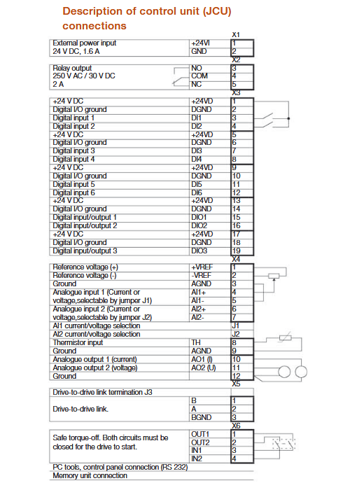
Wiring Details
Below image show terminal details:
Brake Resistance Details
| Model no. | R. Min | P.BR Max |
| 3-phase, 400 V | ohm | KW |
| -02A5-4 | 120 | 5.5 |
| -03A0-4 | 120 | 5.5 |
| -04A0-4 | 120 | 5.5 |
| -05A0-4 | 120 | 5.5 |
| -07A0-4 | 120 | 5.5 |
| -09A5-4 | 80 | 7.9 |
| -012A-4 | 40 | 14.6 |
| -016A-4 | 40 | 14.6 |
| -024A-4 | 20 | 30.7 |
| -031A-4 | 20 | 30.7 |
| -040A-4 | 13 | 43.9 |
| -046A-4 | 13 | 43.9 |
| -060A-4 | 13 | 43.9 |
| -073A-4 | 13 | 43.9 |
| -090A-4 | 13 | 43.9 |
Faults & Alarms
Search from below list for ACSM1 drive faults & alarms:
| Fault Code | Cause & Solution |
|---|---|
| A2000 BRAKE START TORQUE | Cause: Mechanical brake alarm. Alarm is activated if required motor starting torque, 35.06 BRAKE OPEN TORQ, is not achieved. Solution: 1. Check brake open torque setting, parameter 35.06. 2. Check drive torque and current limits. See firmware block LIMITS. 3. This is a Programmable fault: check parameter 35.09 BRAKE FAULT FUNCTION |
| A2001 BRAKE NOT CLOSED | Cause: Mechanical brake control alarm. Alarm is activated, eg, if brake acknowledgement is not as expected during brake closing. Solution: 1. Check mechanical brake connection. 2. Check mechanical brake settings, parameters 35.01…35.09. 3. To determine whether problem is with acknowledgement signal or brake: Check if brake is closed or open. 4. This is a Programmable fault: check parameter 35.09 BRAKE FAULT FUNCTION. |
| A2002 BRAKE NOT OPEN | Cause: Mechanical brake control alarm. Alarm is activated, eg, if brake acknowledgement is not as expected during brake opening. Solution: 1. Check mechanical brake connection. 2. Check mechanical brake settings, parameters 35.01…35.08. 3. To determine whether problem is with acknowledgement signal or brake: Check if brake is closed or open. 4. This is a Programmable fault: check parameter 35.09 BRAKE FAULT FUNCTION. |
| A2003 SAFE TORQUE OFF | Cause: Safe Torque Off function is active, ie, safety circuit signal(s) connected to connector X6 is lost while drive is stopped and parameter 46.07 STO DIAGNOSTIC is set to (2) Alarm. Solution: 1. Check safety circuit connections. 2. This is a Programmable fault: check parameter 46.07 STO DIAGNOSTIC. |
| A2005 MOTOR TEMPERATURE | Cause 1: Estimated motor temperature (based on motor thermal model) has exceeded alarm limit defined by parameter 45.03 MOT TEMP ALM LIM. Solution: 1. Check motor ratings and load. 2. Let motor cool down. 3. Ensure proper motor cooling: Check cooling fan, clean cooling surfaces, etc. 4. Check value of alarm limit. 5. Check motor thermal model settings, parameters 45.06…45.08 and 45.10 MOT THERM TIME. Cause 2: Measured motor temperature has exceeded alarm limit defined by parameter 45.03 MOT TEMP ALM LIM. Solution: 1. Check that actual number of sensors corresponds to value set by parameter 45.02 MOT TEMP SOURCE. 2. Check motor ratings and load. 3. Let motor cool down. 4. Ensure proper motor cooling: Check cooling fan, clean cooling surfaces, etc. 5. Check value of alarm limit. Note: This is a Programmable fault: check parameter 45.01 MOT TEMP PROT. |
| A2006 EMERGENCY OFF | Cause: Drive has received emergency OFF2 command. Solution: To restart drive, activate RUN ENABLE signal (source selected by parameter 10.09 RUN ENABLE) and start drive. |
| A2007 RUN ENABLE | Cause: No Run enable signal is received. Solution: Check setting of parameter 10.09 RUN ENABLE. Switch signal on (eg, in the fieldbus Control Word) or check wiring of selected source. |
A2008 ID-RUN | Cause: Motor identification run is on or motor identification is required. Solution: 1. This alarm belongs to normal start-up procedure. Wait until drive indicates that motor identification is completed. 2. This alarm belongs to normal start-up procedure. 3. Select how motor identification should be performed, parameter 99.13 IDRUN MODE. Start identification routines by pressing Start key. |
| A2009 EMERGENCY STOP | Cause: Drive has received emergency stop command (OFF1/OFF3). Solution: 1. Check that it is safe to continue operation. 2. Return emergency stop push button to normal position (or adjust the fieldbus Control Word accordingly). 3. Restart drive. |
| A2010 POSITION SCALING | Cause: Overflow or underflow in position calculation (caused by used position scaling). Solution: 1. Check position scaling parameter settings: 60.06 FEED CONST NUM…60.09 POS RESOLUTION. 2. Check speed scaling parameter settings: 60.11 POS SPEED2INT and 60.12 POS SPEED SCALE. |
| A2011 BR OVERHEAT | Cause: Braking resistor temperature has exceeded alarm limit defined by parameter 48.07 BR TEMP ALARMLIM. Solution: 1. Stop drive. 2. Let resistor cool down. 3. Check resistor overload protection function settings, parameters 48.01…48.05. 4. Check alarm limit setting, parameter 48.07. 5. Check that braking cycle meets allowed limits. |
| A2012 BC OVERHEAT | Cause: Braking chopper IGBT temperature has exceeded internal alarm limit. Solution: 1. Let chopper cool down. 2. Check for excessive ambient temperature. 3. Check for cooling fan failure. 4. Check for obstructions in the air flow. 5. Check the dimensioning and cooling of the cabinet. 6. Check resistor overload protection function settings, parameters 48.01…48.05. 7. Check that braking cycle meets allowed limits. 8. Check that drive supply AC voltage is not excessive. |
| A2013 DEVICE OVERTEMP | Cause: Measured drive temperature has exceeded internal alarm limit. Solution: 1. Check ambient conditions. 2. Check air flow and fan operation. 3. Check heatsink fins for dust pick-up. 4. Check motor power against unit power. |
| A2014 INTBOARD OVERTEMP | Cause: Interface board (between power unit and control unit) temperature has exceeded internal alarm limit. Solution: 1. Let drive cool down. 2. Check for excessive ambient temperature. 3. Check for cooling fan failure. 4. Check for obstructions in the air flow. 5. Check the dimensioning and cooling of the cabinet. |
| A2015 BC MOD OVERTEMP | Cause: Input bridge or braking chopper temperature has exceeded internal alarm limit. Solution: 1. Let drive cool down. 2. Check for excessive ambient temperature. 3. Check for cooling fan failure. 4. Check for obstructions in the air flow. 5. Check the dimensioning and cooling of the cabinet. |
| A2016 IGBT OVERTEMP | Cause: Drive temperature based on thermal model has exceeded internal alarm limit. Solution: 1. Check ambient conditions. 2. Check air flow and fan operation. 3. Check heatsink fins for dust pick-up. 4. Check motor power against unit power. |
| A2017 FIELDBUS COMM | Cause: Cyclical communication between drive and fieldbus adapter module or between PLC and fieldbus adapter module is lost. Solution: 1. Check status of fieldbus communication. 2. Check fieldbus parameter settings. 3. Check cable connections. 4. Check if communication master can communicate. |
| A2018 LOCAL CTRL LOSS | Cause: Control panel or PC tooln selected as active control location for drive has ceased communicating. Solution: 1. Check PC tool or control panel connection. 2. Check control panel connector. 3. Replace control panel in mounting platform. |
| A2019 AI SUPERVISION | Cause: Analogue input AI1 or AI2 signal has reached limit defined by parameter 13.13 AI SUPERVIS ACT. Solution: 1. Check analogue input AI1/2 source and connections. 2. Check analogue input AI1/2 minimum and maximum limit settings, parameters 13.02 and 13.03 / 13.07 and 13.08. 3. This is a Programmable fault: check parameter 13.12 AI SUPERVISION |
| A2020 FB PAR CONF | Cause: The drive does not have a functionality requested by PLC, or requested functionality has not been activated. Solution: 1. Check PLC programming. 2. Check fieldbus parameter settings. |
| A2021 NO MOTOR DATA | Cause: Parameters in group 99 have not been set. Solution: 1. Check that all the required parameters in group 99 have been set. Note: It is normal for this alarm to appear during the start-up until the motor data is entered. |
| A2022 ENCODER 1 FAILURE | Cause: Encoder 1 has been activated by parameter but the encoder interface (FEN-xx) cannot be found. Solution: 1. Check parameter 90.01 ENCODER 1 SEL setting corresponds to encoder interface 1 (FEN-xx) installed in drive Slot 1/2 (signal 9.20 OPTION SLOT 1 / 9.21 OPTION SLOT 2). Note: The new setting will only take effect after parameter 90.10 ENC PAR REFRESH is used or after the JCU control unit is powered up the next time. |
| A2023 ENCODER 2 FAILURE | Cause 1: Encoder 2 has been activated by parameter but the encoder interface (FEN-xx) cannot be found. Solution: 1. Check parameter 90.02 ENCODER 2 SEL setting corresponds to encoder interface 2 (FEN-xx) installed in drive Slot 1/2 (signal 9.20 OPTION SLOT 1 / 9.21 OPTION SLOT 2). Note: The new setting will only take effect after parameter 90.10 ENC PAR REFRESH is used or after the JCU control unit is powered up the next time. Cause 2: EnDat or SSI encoder is used in continuous mode as encoder 2. [I.e. 90.02 ENCODER 2 SEL = (3) FEN-11 ABS and 91.02 ABS ENC INTERF = (2) EnDat or (4) SSI) and 91.30 ENDAT MODE = (1) Continuous (or 91.25 SSI MODE = (1) Continuous).] Solution: 1. If possible, use single position transfer instead of continuous position transfer (i.e. if encoder has incremental sin/cos signals): – Change parameter 91.25 SSI MODE / 91.30 ENDAT MODE to value (0) Initial pos.. Otherwise use EnDat/SSI encoder as encoder 1: – Change parameter 90.01 ENCODER 1 SEL to value (3) FEN-11 ABS and parameter 90.02 ENCODER 2 SEL to value (0) None. Note: The new setting will only take effect after parameter 90.10 ENC PAR REFRESH is used or after the JCU control unit is powered up the next time. |
| A2024 LATCH POS 1 FAILURE | Cause: Position latch 1 from encoder 1 or 2 has failed. Solution: 1. Check latch source parameter settings: 62.04 HOME SWITCH TRIG, 62.12 PRESET TRIG, 62.15 TRIG PROBE1 and 62.17 TRIG PROBE2. Note that zero pulse is not always supported. * 2. Check that appropriate encoder interface 1/2 is activated by parameter 90.10 ENCODER 1 SEL / 90.02 ENCODER 2 SEL. Note: The new setting will only take effect after parameter 90.10 ENC PAR REFRESH is used or after the JCU control unit is powered up the next time. * – Zero pulse is supported when TTL input of encoder interface module is selected (i.e. par. 90.01/90.02 = (1) FEN-01 TTL+, (2) FEN-01 TTL, (4) FEN-11 TTL or (6) FEN-21 TTL. – Zero pulse is supported when absolute encoder input of encoder interface module is selected and zero pulse is enabled (i.e. 90.01/90.02 = (3) FEN-11 ABS and 91.02 = (0) None / (1) Commut sig and 91.05 = (1) TRUE). – Zero pulse is not supported when resolver input is selected (i.e. 90.01/90.02 = (5) FEN- 21 RES). |
| A2025 LATCH POS 2 FAILURE | Cause: Position latch 2 from encoder 1 or 2 has failed. Solution: 1. Check latch source parameter settings: 62.04 HOME SWITCH TRIG, 62.12 PRESET TRIG, 62.15 TRIG PROBE1 and 62.17 TRIG PROBE2. Note that zero pulse is not always supported. * 2. Check that appropriate encoder interface 1/2 is activated by parameter 90.10 ENCODER 1 SEL / 90.02 ENCODER 2 SEL. Note: The new setting will only take effect after parameter 90.10 ENC PAR REFRESH is used or after the JCU control unit is powered up the next time. * – Zero pulse is supported when TTL input of encoder interface module is selected (i.e. par. 90.01/90.02 = (1) FEN-01 TTL+, (2) FEN-01 TTL, (4) FEN-11 TTL or (6) FEN-21 TTL. – Zero pulse is supported when absolute encoder input of encoder interface module is selected and zero pulse is enabled (i.e. 90.01/90.02 = (3) FEN-11 ABS and 91.02 = (0) None / (1) Commut sig and 91.05 = (1) TRUE). – Zero pulse is not supported when resolver input is selected (i.e. 90.01/90.02 = (5) FEN- 21 RES). |
| A2026 ENC EMULATION FAILURE | Cause: Encoder emulation error. Solution: 1. If position value used in emulation is measured by encoder: – Check that FEN-xx encoder used in emulation (90.03 EMUL MODE SEL) corresponds to FEN-xx encoder interface 1 or (and) 2 activated by parameter 90.01 ENCODER 1 SEL / 90.02 ENCODER 2 SEL. (Parameter 90.01/90.02 activates the position calculation of the used FEN-xx input). 2. If position value used in emulation is determined by drive software: – Check that FEN-xx encoder used in emulation (90.03 EMUL MODE SEL) corresponds to FEN-xx encoder interface 1 or (and) 2 activated by parameter 90.01 ENCODER 1 SEL / 90.02 ENCODER 2 SEL (because position data used in emulation is written to FEN-xx during encoder data request). Encoder interface 2 is recommended. Note: The new setting will only take effect after parameter 90.10 ENC PAR REFRESH is used or after the JCU control unit is powered up the next time. |
| A2027 FEN TEMP MEAS FAILURE | Cause 1: Error in temperature measurement when temperature sensor (KTY or PTC) connected to encoder interface FEN-xx is used. Solution: 1. Check that parameter 45.02 MOT TEMP SOURCE setting corresponds to encoder interface installation (9.20 OPTION SLOT 1 / 9.21 OPTION SLOT 2): 2. If one FEN-xx module is used: – Parameter 45.02 MOT TEMP SOURCE setting must be either (2) KTY 1st FEN or (5) PTC 1st FEN. FEN-xx module can be in either Slot 1 or Slot 2. 3. If two FEN-xx modules are used: – When parameter 45.02 MOT TEMP SOURCE setting is (2) KTY 1st FEN or (5) PTC 1st FEN, the encoder installed in drive Slot 1 is used. – When parameter 45.02 MOT TEMP SOURCE setting is (3) KTY 2nd FEN or (6) PTC 2nd FEN, the encoder installed in drive Slot 2 is used. Cause 2: Error in temperature measurement when KTY sensor connected to encoder interface FEN-01 is used. Solution: 1. FEN-01 does not support temperature measurement with KTY sensor. Use PTC sensor or other encoder interface module. |
| A2028 ENC EMUL MAX FREQ | Cause: TTL pulse frequency used in encoder emulation exceeds maximum allowed limit (500 kHz). Solution: Decrease parameter 93.21 EMUL PULSE NR value. Note: The new setting will only take effect after parameter 90.10 ENC PAR REFRESH is used or after the JCU control unit is powered up the next time. |
| A2029 ENC EMUL REF ERROR | Cause: Encoder emulation has failed due to failure in writing new (position) reference for emulation. Solution: There is an hardware or software issue in drive, need to repaur or replace drive. |
| A2030 RESOLVER AUTOTUNE ERR | Cause: Resolver autotuning routines, which are automatically started when resolver input is activated for the first time, have failed. Solution: 1. Check cable between resolver and resolver interface module (FEN-21) and order of connector signal wires at both ends of cable. 2. Check resolver parameter settings. Note: Resolver autotuning routines should always be performed after resolver cable connection has been modified. Autotuning routines can be activated by setting parameter 92.02 EXC SIGNAL AMPL or 92.03 EXC SIGNAL FREQ, and then setting parameter 90.10 ENC PAR REFRESH to (1) Configure. |
| A2031 ENCODER 1 CABLE | Cause: Encoder 1 cable fault detected. Solution: 1. Check cable between FEN-xx interface and encoder 2. After any modifications in cabling, re-configure interface by switching drive power off and on, or by activating parameter 90.10 ENC PAR REFRESH. |
| A2032 ENCODER 2 CABLE | Cause: Encoder 2 cable fault detected. Solution: 1. Check cable between FEN-xx interface and encoder 2. 2. After any modifications in cabling, re-configure interface by switching drive power off and on, or by activating parameter 90.10 ENC PAR REFRESH. |
| A2033 D2D COMMUNICATION | Cause 1: On the master drive: The drive has not been replied to by an activated follower for five consecutive polling cycles. Solution: 1. Check that all drives that are polled (parameters 57.04 and 57.05) on the drive-to- drive link are powered, properly connected to the link, and have the correct node address. 2. Check the drive-to-drive link wiring. Cause 2: On a follower drive: The drive has not received new reference 1 and/or 2 for five consecutive reference handling cycles. Note: This is a Programmable fault: check parameter 57.02 COMM LOSS FUNCTION Solution: 1. Check the settings of parameters 57.06 and 57.07 on the master drive. 2. Check the drive-to-drive link wiring. |
| A2034 D2D BUFFER OVERLOAD | Cause: Transmission of drive-to-drive references failed because of message buffer overflow. Solution: 1. This is a Programmable fault: check parameter 57.02 COMM LOSS FUNCTION. 2. There is an hardware or software issue in drive, need to repaur or replace drive. |
| A2035 PS COMM | Cause: Communication errors detected between the JCU Control Unit and the power unit of the drive. Solution: 1. Check the connections between the JCU Control Unit and the power unit. 2. If the JCU is powered from an external supply, ensure that parameter 95.01 CTRL UNIT SUPPLY is set to (1) External 24V. |
| A2036 RESTORE | Cause: Restoration of backed-up parameters failed. Solution: There is an hardware or software issue in drive, need to repaur or replace drive. |
| A2037 CUR MEAS CALIBRATION | Cause: Current measurement calibration will occur at next start. Solution: This is a informative alarm. |
| A2038 AUTOPHASING | Cause: Autophasing will occur at next start. Solution: This is a informative alarm. |
| A2039 EARTH FAULT | Cause: Drive has detected load unbalance typically due to earth fault in motor or motor cable. Solution: 1. Check that there are no power factor correction capacitors or surge absorbers in motor cable. 2. Check that there is no earth fault in motor or motor cables: – measure insulation resistances of motor and motor cable. 3. If no earth fault can be detected then there is an hardware or software issue in drive, need to repaur or replace drive. |
| A2041 MOTOR NOM VALUE | Cause: The motor configuration parameters are set incorrectly or the drive is not dimensioned correctly. Solution: 1. Check the settings of the motor configuration parameters in group 99. 2. Check that the drive is sized correctly for the motor. |
| A2042 D2D CONFIG | Cause: The settings of drive-to-drive link configuration parameters (group 57) are incompatible. Solution: 1. Check the settings of the parameters in group 57 D2D communication. |
| A2043 STALL | Cause: Motor is operating in stall region because of e.g. excessive load or insufficient motor power. Solution: 1. Check motor load and drive ratings. 2. Check fault function parameters. 3. This is a Programmable fault: check parameter 30.09 Stall function. |
| A2047 SPEED FEEDBACK | Cause: No speed feedback is received. Solution: 1. Check the settings of the parameters in group 22. 2. Check encoder installation. See the description of fault 0039 (ENCODER1) for more information. 3. Check encoder cabling. |
| A2048 OPTION COMM LOSS | Cause: Communication between drive and option module (FEN-xx and/or FIO-xx) is lost. Solution: 1. Check that option modules are properly connected to Slot 1 and (or) Slot 2. 2. Check that option modules or Slot 1/2 connectors are not damaged. To determine whether module or connector is damaged: Test each module individually in Slot 1 and Slot 2. |
| A2072 DC NOT CHARGED | Cause: The voltage of the intermediate DC circuit has not yet risen to operating level. Solution: Wait for the DC voltage to rise. |
| A2073 SPEED CTRL TUNE FAIL | Cause: Speed controller autotune routine did not finish successfully. Solution: See parameter 28.16 PI TUNE MODE. |
| 2075 LOW VOLT MODE CONFIG | Cause: Low voltage mode has been activated but the parameter settings are outside allowable limits. Solution: 1. Check the Low voltage mode parameters in group 47. |
| A2079 ENC 1 PULSE FREQUENCY | Cause: Encoder 1 is receiving too high data flow (pulse frequency). Solution: 1. Check encoder settings. 2. Change parameters 93.03 ENC1 SP CALCMODE and 93.13 ENC2 SP CALCMODE to use only one channel pulses/ edges. |
| A2080 ENC 2 PULSE FREQUENCY | Cause: Encoder 2 is receiving too high data flow (pulse frequency). Solution: 1. Check encoder settings. 2. Change parameters 93.03 ENC1 SP CALCMODE and 93.13 ENC2 SP CALCMODE to use only one channel pulses/ edges. |
| A2082 BR DATA | Cause: Brake chopper is configured wrong. Solution: 1. Check the brake chopper configuration in parameter group 48. |
| F0001 OVERCURRENT | Cause: Output current has exceeded internal fault limit. Solution: 1. Check motor load. 2. Check acceleration time. See parameter group 25 on page 161. 3. Check motor and motor cable (including phasing and delta/star connection). 4. Check that the start-up data in parameter group 99 corresponds to the motor rating plate. 5. Check that there are no power factor correction capacitors or surge absorbers in motor cable. 6. Check encoder cable (including phasing). |
| F0002 DC OVERVOLTAGE | Cause: Excessive intermediate circuit DC voltage. Solution: 1. Check that overvoltage controller is on, parameter 47.01 OVERVOLTAGE CTRL. 2. Check mains for static or transient overvoltage. 3. Check braking chopper and resistor (if used). 4. Check deceleration time. 5. Use coast-to-stop function (if applicable). 6. Retrofit frequency converter with braking chopper and braking resistor. |
| F0003 DEVICE OVERTEMP | Cause: Measured drive temperature has exceeded internal fault limit. Solution: 1. Check ambient conditions. 2. Check air flow and fan operation. 3. Check heatsink fins for dust pick-up. 4. Check motor power against unit power. |
| F0004 SHORT CIRCUIT | Cause: Short-circuit in motor cable(s) or motor Solution: 1. Check motor and motor cable. 2. Check there are no power factor correction 3. capacitors or surge absorbers in motor cable. |
| F0005 DC UNDERVOLTAGE | Cause: Intermediate circuit DC voltage is not sufficient due to missing mains phase, blown fuse or rectifier bridge internal fault. Solution: 1. Check mains supply and fuses. |
| F0006 EARTH FAULT | Cause: Drive has detected load unbalance typically due to earth fault in motor or motor cable. Solution: 1. Check there are no power factor correction capacitors or surge absorbers in motor cable. 2. Check that there is no earth fault in motor or motor cables: – measure insulation resistances of motor and motor cable. |
| F0007 FAN FAULT | Cause: Fan is not able to rotate freely or fan is disconnected. Fan operation is monitored by measuring fan current. Solution: 1. Check fan operation and connection. |
| F0008 IGBT OVERTEMP | Cause: Drive temperature based on thermal model has exceeded internal fault limit. Solution: 1. Check ambient conditions. 2. Check air flow and fan operation. 3. Check heatsink fins for dust pick-up. 4. Check motor power against unit power. |
| F0009 BC WIRING | Cause: Brake resistor short circuit or brake chopper control fault Solution: 1. Check brake chopper and brake resistor connection. 2. Ensure brake resistor is not damaged. |
| F0010 BC SHORT CIRCUIT | Cause: Short circuit in brake chopper IGBT Solution: 1. Replace brake chopper. 2. Ensure brake resistor is connected and not damaged. |
| F0011 BC OVERHEAT | Cause: Brake chopper IGBT temperature has exceeded internal alarm limit. Solution: 1. Let chopper cool down. 2. Check resistor overload protection function settings (parameters 48.01…48.05). 3. Check that braking cycle meets allowed limits. 4. Check that drive supply AC voltage is not excessive. |
| F0012 BR OVERHEAT | Cause: Brake resistor temperature has exceeded fault limit defined by parameter 48.06 Br temp faultlimit. Solution: 1. Stop drive. 2. Let resistor cool down. 3. Check resistor overload protection function settings (parameters 48.01…48.05). 4. Check fault limit setting, parameter 48.06 Br temp faultlim. 5. Check that braking cycle meets allowed limits. |
| F0013 CURR MEAS GAIN | Cause: Difference between output phase U2 and W2 current measurement gain is too great. Solution: There is an hardware or software issue in drive, need to repaur or replace drive. |
| F0014 CABLE CROSS CONNECTION | Cause: Incorrect input power and motor cable connection (i.e. input power cable is connected to drive motor connection). Solution: 1. Check input power connections. |
| F0015 SUPPLY PHASE | Cause: Intermediate circuit DC voltage is oscillating due to missing input power line phase or blown fuse. Solution: 1. Check input power line fuses. 2. Check for input power supply imbalance. |
| F0016 MOTOR PHASE | Cause: Motor circuit fault due to missing motor connection (all three phases are not connected). Solution: 1. Connect motor cable. |
| F0017 ID-RUN FAULT | Cause: Motor ID Run is not completed successfully. Solution: Check the fault logger for a fault code extension. See appropriate actions for each extension below. Extension: 1 – The motor ID run cannot be completed because the maximum current setting and/or the internal current limit of the drive is too low. Check setting of parameters 99.06 MOT NOM CURRENT and 20.05 MAXIMUM CURRENT. Make sure that 20.05 MAXIMUM CURRENT > 99.06 MOT NOM CURRENT. Check that the drive is dimensioned correctly according to the motor. Extension: 2 The motor ID run cannot be completed because the maximum speed setting and/or calculated field weakening point is too low. Check setting of parameters 99.07 MOT NOM VOLTAGE, 99.08 MOT NOM FREQ, 99.09 MOT NOM SPEED, 20.01 MAXIMUM SPEED and 20.02 MINIMUM SPEED. Make sure that • 20.01 MAXIMUM SPEED > (0.55 × 99.09 MOT NOM SPEED) > (0.50 × synchronous speed), • 20.02 MINIMUM SPEED < 0, and • supply voltage > (0.66 × 99.07 MOT NOM VOLTAGE). Extension: 3 The motor ID run cannot be completed because the maximum torque setting is too low. Check setting of parameters 99.12 MOT NOM TORQUE and 20.06 MAXIMUM TORQUE. Make sure that 20.06 MAXIMUM TORQUE > 100%. Extension: 5…8 Internal error. Extension: 9 Asynchronous motors only: Acceleration did not finish within reasonable time. Extension: 10 Asynchronous motors only: Deceleration did not finish within reasonable time. Extension: 11 Asynchronous motors only: Speed dropped to zero during motor ID run. Extension: 12 Permanent magnet motors only: First acceleration did not finish within reasonable time. Extension: 13 Permanent magnet motors only: Second acceleration did not finish within reasonable time. Extension: 14…16 Internal error. |
| F0018 CURR U2 MEAS | Cause: Measured offset error of U2 output phase current measurement is too great. (Offset value is updated during current calibration.) Solution: There is an hardware or software issue in drive, need to repaur or replace drive. |
| F0019 CURR V2 MEAS | Cause: Measured offset error of V2 output phase current measurement is too great. (Offset value is updated during current calibration.) Solution: There is an hardware or software issue in drive, need to repaur or replace drive. |
| F0020 CURR W2 MEAS | Cause: Measured offset error of W2 output phase current measurement is too great. (Offset value is updated during current calibration.) Solution: There is an hardware or software issue in drive, need to repaur or replace drive. |
| F0021 STO1 LOST | Cause: Safe Torque Off function is active, i.e. safety circuit signal 1 connected between X6:1 and X6:3 is lost while drive is at stopped state and parameter 46.07 STO DIAGNOSTIC setting is (2) Alarm or (3) No. Solution: 1. Check safety circuit connections. |
| F0022 STO2 LOST | Cause: Safe Torque Off function is active, i.e. safety circuit signal 2 connected between X6:2 and X6:4 is lost while drive is at stopped state and parameter 46.07 STO DIAGNOSTIC setting is (2) Alarm or (3) No. Solution: 1. Check safety circuit connections. |
| F0024 INTBOARD OVERTEMP | Cause: Interface board (between power unit and control unit) temperature has exceeded internal fault limit. Solution: 1. Let drive cool down. 2. Check for excessive ambient temperature. 3. Check for cooling fan failure. 4. Check for obstructions in the air flow. 5. Check the dimensioning and cooling of the cabinet. |
| F0025 BC MOD OVERTEMP | Cause: Input bridge or brake chopper temperature has exceeded internal fault limit. Solution: 1. Let drive cool down. 2. Check for excessive ambient temperature. 3. Check for cooling fan failure. 4. Check for obstructions in the air flow. 5. Check the dimensioning and cooling of the cabinet. |
| F0026 AUTOPHASING | Cause: Autophasing routine failed because the estimated angle of the rotor differs too much from the measured angle of the rotor. Solution: 1. Try other autophasing modes (see parameter 11.07 AUTOPHASING MODE) if possible. 2. In addition, repeat autophasing multiple times and check the value in parameter 97.20 POS OFFSET USER between separate runs (see section Autophasing). The value should not change between consecutive autophasing runs. 3. Check that there is no slip in the encoder connection to the motor axle. Because of the slip the estimated and measured drive speed may differ during fast accelerations/ decelerations. |
| F0027 PU LOST | Cause: Connection between the JCU Control Unit and the power unit of the drive is lost. Solution: 1. Check the connections between the JCU 2. Control Unit and the power unit. |
| F0028 PS COMM | Cause: Communication errors detected between the JCU Control Unit and the power unit of the drive. Solution: 1. Check the connections between the JCU Control Unit and the power unit. |
| F0029 IN CHOKE TEMP | Cause: Temperature of internal AC choke excessive. Solution: 1. Check cooling fan. |
| F0030 EXTERNAL | Cause: Fault in external device. (This information is configured through one of programmable digital inputs.) Solution: 1. Check external devices for faults. 2. Check setting of parameter 46.01 EXTERNAL FAULT. |
| F0031 SAFE TORQUE OFF | Cause: Safe Torque Off function is active, i.e. safety circuit signal(s) connected to connector X6 is lost – during drive start or drive run or – while drive is stopped and parameter 46.07 STO DIAGNOSTIC setting is (1) Fault. Solution: 1. Check safety circuit connections. |
| F0032 OVERSPEED | Cause: Motor is turning faster than highest allowed speed due to incorrectly set minimum/ maximum speed, insufficient braking torque or changes in load when using torque reference. Solution: 1. Check minimum/maximum speed settings, parameters 20.01 Maximum speed and 20.02 Minimum speed. 2. Check adequacy of motor braking torque. 3. Check applicability of torque control. 4. Check need for brake chopper and resistor(s). |
| F0033 BRAKE START TORQUE | Cause: Mechanical brake fault. Fault is activated if required motor starting torque, 35.06 BRAKE OPEN TORQ, is not achieved. Solution: 1. Check brake open torque setting, parameter 35.06. 2. Check drive torque and current limits. |
| F0034 BRAKE NOT CLOSED | Cause: Mechanical brake control fault. Fault is activated if brake acknowledgement is not as expected during brake closing. Solution: 1. Check mechanical brake connection. 2. Check mechanical brake settings, parameters 35.01…35.09. 3. To determine whether problem is with acknowledgement signal or brake: Check if brake is closed or open. |
| F0035 BRAKE NOT OPEN | Cause: Mechanical brake control fault. Fault is activated if brake acknowledgement is not as expected during brake opening. Solution: 1. Check mechanical brake connection. 2. Check mechanical brake settings, parameters 35.01…35.08. 3. To determine whether problem is with acknowledgement signal or brake: Check if brake is closed or open. |
| F0036 LOCAL CTRL LOSS | Cause: Control panel or PC tool selected as active control location for drive has ceased communicating. Solution: 1. Check PC tool or control panel connection. 2. Check control panel connector. 3. Replace control panel in mounting platform. |
| F0037 NVMEM CORRUPTED | Cause: Drive internal fault. Note: This fault cannot be reset. Solution: There is an hardware or software issue in drive, need to repaur or replace drive. |
| F0038 OPTION COMM LOSS | Cause: Communication between drive and option module (FEN-xx and/or FIO-xx) is lost. Solution: 1. Check that option modules are properly connected to Slot 1 and (or) Slot 2. 2. Check that option modules or Slot 1/2 connectors are not damaged. To determine whether module or connector is damaged: 3. Test each module individually in Slot 1 and Slot 2. |
| F0039 ENCODER1 | Cause: Encoder 1 feedback fault. Solution: 1. If fault appears during first start-up before encoder feedback is used: – Check cable between encoder and encoder interface module (FEN-xx) and order of connector signal wires at both ends of cable. 2. If fault appears after encoder feedback has already been used or during drive run: – Check that encoder connection wiring or encoder is not damaged. – Check that encoder interface module (FEN-xx) connection or module is not damaged. – Check earthings (when disturbances are detected in communication between encoder interface module and encoder). |
| F0040 ENCODER2 | Cause: Encoder 2 feedback fault. Solution: 1. If fault appears during first start-up before encoder feedback is used: – Check cable between encoder and encoder interface module (FEN-xx) and order of connector signal wires at both ends of cable. 2. If fault appears after encoder feedback has already been used or during drive run: – Check that encoder connection wiring or encoder is not damaged. – Check that encoder interface module (FEN-xx) connection or module is not damaged. – Check earthings (when disturbances are detected in communication between encoder interface module and encoder). |
| F0041 POSITION ERROR | Cause: Calculated position error, 4.19 POS ERROR, exceeds defined position error supervision window. Motor is stalled. Solution: 1. Check supervision window setting, parameter 71.06 POS ERR LIM. 2. Check that no torque limit is exceeded during positioning. |
| F0043 POSITION ERROR MIN | Cause: Actual position value exceeds defined minimum position value. Limit can be exceeded because no homing (or preset function) has been performed. Solution: 1. Check minimum position setting, parameter 60.14 MINIMUM POS. 2. Perform homing (or preset function). |
| F0044 POSITION ERROR MAX | Cause: Actual position value exceeds defined maximum position value. Limit can be exceeded because no homing (or preset function) has been performed. Solution: 1. Check maximum position setting, parameter 60.13 MAXIMUM POS. 2. Perform homing (or preset function). |
| F0045 FIELDBUS COMM | Cause: Cyclical communication between drive and fieldbus adapter module or between PLC and fieldbus adapter module is lost. Solution: 1. Check status of fieldbus communication. 2. Check fieldbus parameter settings. 3. Check cable connections. 4. Check if communication master can communicate. |
| F0046 FB MAPPING FILE | Cause: Drive internal fault. Solution: There is an hardware or software issue in drive, need to repaur or replace drive. |
| F0047 MOTOR OVERTEMP | Cause 1: Estimated motor temperature (based on motor thermal model) has exceeded fault limit defined by parameter 45.04 MOT TEMP FLT LIM. Solution: 1. Check motor ratings and load. 2. Let motor cool down. 3. Ensure proper motor cooling: Check cooling fan, clean cooling surfaces, etc. 4. Check value of fault limit. 5. Check motor thermal model settings, parameters 45.06…45.08 and 45.10 MOT THERM TIME. Cause 2: Measured motor temperature has exceeded fault limit defined by parameter 45.04 MOT TEMP FLT LIM. Solution: 1. Check that actual number of sensors corresponds to value set by parameter 45.02 MOT TEMP SOURCE. 2. Check motor ratings and load. 3. Let motor cool down. 4. Ensure proper motor cooling: Check cooling fan, clean cooling surfaces, etc. 5. Check value of fault limit. |
| F0048 POS ACT MEASURE | Cause: Selected operation mode requires position feedback data (actual position), but no feedback data is available. Solution: 1. Check actual position source setting, 60.01 POS ACT SEL. 2. Check encoder installation. See ENCODER1 fault description for more information. (The used operation mode is indicated by signal 6.12 OP MODE ACK.) |
| F0049 AI SUPERVISION | Cause: Analogue input AI1 or AI2 signal has reached limit defined by parameter 13.13 AI SUPERVIS ACT. Solution: 1. Check analogue input AI1/2 source and connections. 2. Check analogue input AI1/2 minimum and maximum limit settings, parameters 13.02 and 13.03 / 13.07 and 13.08. |
| F0050 ENCODER 1 CABLE | Cause: Encoder 1 cable fault detected. Solution: 1. Check cable between FEN-xx interface and encoder 1. 2. After any modifications in cabling, re-configure interface by switching drive power off and on, or by activating parameter 90.10 Enc par refresh. |
| F0051 ENCODER 2 CABLE | Cause: Encoder 2 cable fault detected. Solution: 1. Check cable between FEN-xx interface and encoder 2. 2. After any modifications in cabling, re-configure interface by switching drive power off and on, or by activating parameter 90.10 Enc par refresh. |
| F0052 D2D CONFIG | Cause: Configuration of the drive-to- drive link has failed for a reason other than those indicated by alarm A-2042, for example start inhibition is requested but not granted. Solution: There is an hardware or software issue in drive, need to repaur or replace drive. |
| F0053 D2D COMM | Cause 1: On the master drive: The drive has not been replied to by an activated follower for five consecutive polling cycles. Solution: 1. Check that all drives that are polled (parameters 57.04 Follower mask 1 and 57.05 Follower mask 2) on the drive-to- drive link are powered, properly connected to the link, and have the correct node address. 2. Check the drive-to-drive link wiring. Cause 2: On a follower drive: The drive has not received new reference 1 and/or 2 for five consecutive reference handling cycles. Solution: 1. Check the settings of parameters 57.06 Ref 1 src and 57.07 Ref 2 src) on the master drive. 2. Check the drive-to-drive link wiring. |
| F0054 D2D BUF OVERLOAD | Cause: Transmission of drive-to-drive references failed because of message buffer overflow. |
| F0055 TECH LIB | Cause: Resettable fault generated by a technology library. Solution: Refer to the documentation of the technology library. |
| F0056 TECH LIB CRITICAL | Cause: Permanent fault generated by a technology library. Solution: Refer to the documentation of the technology library. |
| F0057 FORCED TRIP | Cause: Generic Drive Communication Profile trip command. Solution: Check PLC status. |
| F0058 FB PAR ERROR | Cause: The drive does not have a functionality requested by PLC, or requested functionality has not been activated. Solution: 1. Check PLC programming. 2. Check settings of parameter group 50 Fieldbus. |
| F0059 STALL | Cause: Motor is operating in stall region because of e.g. excessive load or insufficient motor power. Solution: 1. Check motor load and drive ratings. 2. Check fault function parameters. 3. This is a Programmable fault: check parameter 30.09 Stall function. |
| F0061 SPEED FEEDBACK | Cause: No speed feedback is received. Solution: 1. Check the settings of the parameters in group 22 Speed calculation. 2. Check encoder installation. See the description of fault 0039 (ENCODER1) for more information. |
| F0062 D2D SLOT COMM | Cause: Drive-to-drive link is set to use an FMBA module for communication, but no module is detected in specified slot. Solution: 1. Check the settings of parameters 57.01 and 57.15. Ensure that the FMBA module has been detected by checking parameters 09.20…09.22. 2. Check that the FMBA module is correctly wired. 3. Try installing the FMBA module into another slot. |
| F0067 FPGA ERROR1 | Cause: Drive internal fault. Solution: There is an hardware or software issue in drive, need to repaur or replace drive. |
| F0068 FPGA ERROR2 | Cause: Drive internal fault. Solution: There is an hardware or software issue in drive, need to repaur or replace drive. |
| F0069 ADC ERROR | Cause: Drive internal fault. Solution: There is an hardware or software issue in drive, need to repaur or replace drive. |
| F0073 ENC 1 PULSE FREQUENCY | Cause: Encoder 1 is receiving too high data flow (pulse frequency). Solution: 1. Check encoder settings. 2. Change parameters 93.03 ENC1 SP CALCMODE and 93.13 ENC2 SP CALCMODE to use only one channel pulses/ edges. |
| F0074 ENC 2 PULSE FREQUENCY | Cause: Encoder 2 is receiving too high data flow (pulse frequency). Solution: 1. Check encoder settings. 2. Change parameters 93.03 ENC1 SP CALCMODE and 93.13 ENC2 SP CALCMODE to use only one channel pulses/ edges. |
| F0075 MOT OVERFREQUENCY | Cause: Inverter output (motor) frequency has exceeded the frequency limit 599 Hz. Solution: 1. Reduce the motor rotation speed. |
| F0201 T2 OVERLOAD | Cause: Firmware time level 2 overload. Solution: There is an hardware or software issue in drive, need to repaur or replace drive. |
| F0202 T3 OVERLOAD | Cause: Firmware time level 3 overload. Solution: There is an hardware or software issue in drive, need to repaur or replace drive. |
| F0203 T4 OVERLOAD | Cause: Firmware time level 4 overload. Solution: There is an hardware or software issue in drive, need to repaur or replace drive. |
| F0204 T5 OVERLOAD | Cause: Firmware time level 5 overload. Solution: There is an hardware or software issue in drive, need to repaur or replace drive. |
| F0205 A1 OVERLOAD | Cause: Application time level 1 fault. Solution: There is an hardware or software issue in drive, need to repaur or replace drive. |
| F0206 A2 OVERLOAD | Cause: Application time level 2 fault. Solution: There is an hardware or software issue in drive, need to repaur or replace drive. |
| F0207 A1 INIT FAULT | Cause: Application task creation fault. Solution: There is an hardware or software issue in drive, need to repaur or replace drive. |
| F0208 A2 INIT FAULT | Cause: Application task creation fault. Solution: There is an hardware or software issue in drive, need to repaur or replace drive. |
| F0209 STACK ERROR | Cause: Drive internal fault. Solution: There is an hardware or software issue in drive, need to repaur or replace drive. |
| F0210 JMU MISSING | Cause: JMU Memory Unit is missing or broken. Solution: 1. Check that the JMU is properly installed. If the problem persists, replace the JMU. |
| F0301 UFF FILE READ | Cause: File read error. Solution: There is an hardware or software issue in drive, need to repaur or replace drive. |
| F0302 APPL DIR CREATION | Cause: Drive internal fault. Solution: There is an hardware or software issue in drive, need to repaur or replace drive. |
| F0303 FPGA CONFIG DIR | Cause: Drive internal fault. Solution: There is an hardware or software issue in drive, need to repaur or replace drive. |
| F0304 PU RATING ID | Cause: Drive internal fault. Solution: There is an hardware or software issue in drive, need to repaur or replace drive. |
| F0305 RATING DATABASE | Cause: Drive internal fault. Solution: There is an hardware or software issue in drive, need to repaur or replace drive. |
| F0306 LICENSING | Cause: Drive internal fault. Solution: There is an hardware or software issue in drive, need to repaur or replace drive. |
| F0307 DEFAULT FILE | Cause: Drive internal fault. Solution: There is an hardware or software issue in drive, need to repaur or replace drive. |
| F0308 APPLFILE PAR Conf | Cause: Corrupted application file. Note: This fault cannot be reset. Solution: 1. Reload application. 2. If fault is still active there is an hardware or software issue in drive, need to repaur or replace drive. |
| F0309 APPL LOADING | Cause: Corrupted application file. Solution: 1. Reload application. 2. If fault is still active there is an hardware or software issue in drive, need to repaur or replace drive. |
| F0310 USERSET LOAD | Cause: Loading of user set is not successfully completed because: – requested user set does not exist – user set is not compatible with drive program – drive has been switched off during loading. Solution: 1. Reload. |
| F0311 USERSET SAVE | Cause: User set is not saved because of memory corruption. Solution: 1. Check the setting of parameter 95.01 Ctrl boardSupply. 2. If the fault still occurs there is an hardware or software issue in drive, need to repaur or replace drive. |
| F0312 UFF OVERSIZE | Cause: UFF file is too big. Solution: There is an hardware or software issue in drive, need to repaur or replace drive. |
| F0313 UFF EOF | Cause: UFF file structure failure. Solution: 1. Delete file. 2. After this problem remain same then there is an hardware or software issue in drive, need to repaur or replace drive. |
| F0314 TECH LIB INTERFACE | Cause: Incompatible firmware interface. Solution: There is an hardware or software issue in drive, need to repaur or replace drive. |
| F0315 RESTORE FILE | Cause: Restoration of backed-up parameters failed. Solution: There is an hardware or software issue in drive, need to repaur or replace drive. |
| F0316 DAPS MISMATCH | Cause: Mismatch between JCU Control Unit firmware and power unit logic versions. Solution: There is an hardware or software issue in drive, need to repaur or replace drive. |
| F0317 SOLUTION FAULT | Cause: Fault generated by function block SOLUTION_FAULT in the solution program. Solution: 1. Check the usage of the SOLUTION_FAULT block in the solution program. |
| F0319 APPL LICENCE | Cause: Drive power unit (JPU) lacks the correct application licence required to use the downloaded application program. Solution: Assign the correct application licence to the drive power unit using the DriveSPC PC tool or remove the protection from the application used. |
| A2076 TEMP MEAS FAILURE | Cause: Problem with internal temperature measurement of the drive. Solution: There is an hardware or software issue in drive, need to repaur or replace drive. |