Download Links
 Download Catalog Download Catalog |
Download Manual |
| Download Hardware Manual |
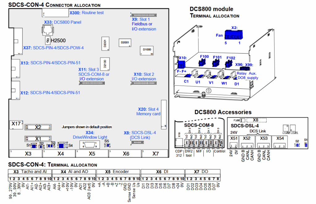
Wiring Details
Below image show terminal details:
Faults & Alarms
Search from below list for DCS800 drive faults & alarms:
| Fault Code | Cause & Solution |
|---|---|
| F501 Auxiliary undervoltage | Cause: The auxiliary voltage is too low while the drive is in operation. Solution: 1. If resetting fails then check following: -internal auxiliary voltages (SDCS-CON-4) -and change SDCS-CON-4 and / or SDCS -PIN-4 respectively SDCS-POW-4 board |
| F511 ConvFanCur | Cause: Converter fan current. only with ConvTempDly (97.05) not equal to 0 and a PW-10002/3 board connected to SDCS-PIN-4/51. Solution: Check: -converter fan supply voltage -converter fan direction of rotation -converter fan components -converter cooling air inlet (e.g. filter) -converter cooling air outlet -connector X12 on SDCS-CON-4 -connector X12 and X22 on SDCS-PIN-4/51 |
| F512 MainsLowVolt | Cause: Mains low (under-) voltage (AC). Solution: Check: – PwrLossTrip (30.21), UNetMin1 (30.22), UNetMin2 (30.23), PowrDownTime (30.24) – if all 3 phases are present: 1. D1 to D4: measure also the fuses F100 to F102 on the SDCS-PIN-4 2. D5 to D7: check also the connections U1, V1 and W1 on the SDCS-PIN-51 – if the mains voltage is within the set tolerance – if the main contactor closes and opens – if the mains voltage scaling is correct [NomMainsVolt (99.10)] – connector X12 and X13 on SDCS-CON-4 – connector X12 and X13 on SDCS-PIN-4/51 – cutting of resistors for voltage coding on SDCS-PIN-51 – D1 to D4: check if the field circuit has no short circuit or ground fault |
| F513 MainsOvrVolt | Cause: Mains overvoltage (AC): Actual mains voltage is > 1.3 * NomMainsVolt (99.10) for more than 10 s and RdyRun = 1. Solution: Check: – if the mains voltage is within the set tolerance – if the mains voltage scaling is correct [NomMainsVolt (99.10)] – connector X12 and X13 on SDCS-CON-4 – connector X12 and X13 on SDCS-PIN-4/51 – cutting of resistors for voltage coding on SDCS-PIN-51 |
| F514 MainsNotSync | Cause: Mains not in synchronism (AC): The synchronization with the mains frequency has been lost. Solution: Check: – mains supply – fuses etc. – mains frequency (50 Hz 5 Hz; 60 Hz 5 Hz) and stability (df/dt = 17 %/s) see PLLIn (3.20) at 50 Hz one period == 360° == 20 ms = 20,000 and at 60 Hz one period == 360° == 16.7 ms = 16,6667 |
| F515 M1FexOverCur | Cause: Motor 1 field exciter overcurrent. Solution: Check: – in case this fault happens during field exciter autotuning deactivate the supervision by setting M1FldOvrCurLev (30.13) = 135 – M1FldOvrCurLev (30.13) – parameter settings of group 44 (field excitation: field current controller tuning) – connections of field exciter – insulation of cables and field winding – resistance of field winding – fault message at field exciter (7-segment display or flashing LED’s) |
| F516 M1FexCom | Cause: Motor 1 field exciter communication loss: Solution: Check: – M1UsedFexType (99.12) – FexTimeOut (94.07) – flat cable connections between SDCS-CON-4 and SDCS-PIN-4 – auxiliary voltage for integrated and external field exciter – DCSLink cable connections – DCSLink termination set dip switch S1100:1 = ON (DCF803-0016, DCF803-0035 and FEX- 425-Int) – DCSLink node ID settings [DCSLinkNodeID (94.01), M1FexNode (94.08) respectively switches S800 and S801 on DCF803-0016, DCF803-0035 and FEX-425-Int] – fault message at field exciter (7-segment display or flashing LED’s) |
| F517 ArmCurRipple | Cause: Armature current ripple: One or several thyristors may carry no current. Solution: Check: – CurRippleSel (30.18), CurRippleLim (30.19) – for too high gain of current controller [M1KpArmCur (43.06)] – current feedback with oscilloscope (6 pulses within one cycle visible?) – branch fuses – thyristor gate-cathode resistance – thyristor gate connection – current transformers (T51, T52) |
| F518 M2FexOverCur | Cause: Motor 2 field exciter overcurrent. Solution: Check: – M2FldOvrCurLev (49.09) – parameter settings of group 49 (field excitation: field current controller tuning) – connections of field exciter – insulation of cables and field winding – resistance of field winding – fault message at field exciter (7-segment display or flashing LED’s) |
| F519 M2FexCom | Cause: Motor 2 field exciter communication loss. Solution: Check: – M2UsedFexType (49.07) – FexTimeOut (94.07) – flat cable connections between SDCS-CON-4 and SDCS-PIN-4 – auxiliary voltage for integrated and external field exciter – DCSLink cable connections – DCSLink termination set dip switch S1100:1 = ON (DCF803-0016, DCF803-0035 and FEX- 425-Int) – DCSLink node ID settings [DCSLinkNodeID (94.01) , M2FexNode (94.09) respectively switches S800 and S801 on DCF803-0016, DCF803-0035 and FEX-425-Int] – fault message at field exciter (7-segment display or flashing LED’s) |
| F521 FieldAck | Cause: Selected motor, field acknowledge missing. Solution: Check: – M1UsedFexType (99.12), if selection matches the field exciter type, Mot1FexStatus (6.12), Mot2FexStatus (6.13) – fault message at field exciter (7-segment display or flashing LED’s) – F521 FieldAck is the sum fault for all field related faults like: 1. F515 M1FexOverCur 2. F516 M1FexCom 3. F529 M1FexNotOK 4. F537 M1FexRdyLost 5. F541 M1FexLowCur |
| F522 SpeedFb | Cause: Selected motor, speed feedback: The comparison of the speed feedback from pulse encoder or analog tacho has failed. Solution: Check: – M1SpeedFbSel (50.03), SpeedFbFltMode (30.36), SpeedFbFltSel (30.17), EMF FbMonLev (30.15), SpeedFbMonLev (30.14) – pulse encoder: encoder itself, alignment, cabling, coupling, power supply (feedback might be too low), mechanical disturbances, jumper S4 on SDCS-CON-4 – analog tacho: tacho itself, tacho polarity and voltage, alignment, cabling, coupling, mechanical disturbances, jumper S1 on SDCS-CON-4 – EMF: connection converter – armature circuit closed – SDCS-CON-4, SDCS-IOB-3, SDCS-POW-4 |
| F523 ExtFanAck | Cause: External fan acknowledge missing. Solution: Check: – MotFanAck (10.06) – external fan contactor – external fan circuit – external fan supply voltage – used digital inputs and outputs (group 14) |
| 524 MainContAck | Cause: Main contactor acknowledge missing. Solution: Check: – MainContAck (10.21) – switch on – off sequence – auxiliary contactor (relay) switching the main contactor after On/Off command – safety relays – used digital inputs and outputs (group 14) |
| F525 TypeCode | Cause: Type code mismatch: When using D1, D2, D3 or D4 modules the current and voltage range of the type code setting is limited to max 1000 ADC and max 600 VAC. Solution: 1. Check: – TypeCode (97.01), S ConvScaleCur (97.02), S ConvScaleVolt (97.03) |
| F526 ExternalDI | Cause: External fault via binary input: There is no problem with the drive itself! Solution: Check: – ExtFaultSel (30.31), ExtFaultOnSel (30.33) |
| F527 ConvFanAck | Cause: Converter fan acknowledge missing. Solution: Check: – ConvFanAck (10.20) – FanDly (21.14) – converter fan contactor – converter fan circuit – converter fan klixon – converter fan components – converter fan supply voltage – converter fan direction of rotation – converter door open – converter cooling air inlet (e.g. filter) – converter cooling air outlet – D6 an D7 pressure switch (setting should be 2 mbar) – used digital inputs and outputs (group 14) |
| F528 FieldBusCom | Cause: Fieldbus communication loss: F528 FieldBusCom is only activated after the first data set from the overriding control is received by the drive. Before the first data set is received only A128 FieldBusCom is active. The reason is to suppress unnecessary faults (the start up of the overriding control is usually slower than the one of the drive). Solution: Check: – CommandSel (10.01), ComLossCtrl (30.28), FB TimeOut (30.35), CommModule (98.02) – parameter settings of group 51 (fieldbus) – fieldbus cable – fieldbus termination – fieldbus adapter |
| F529 M1FexNotOK | Cause: Motor 1 field exciter not okay- A fault was found during self-diagnosis of field exciter or power failure in field exciter 1. Solution: Check: – field exciter operation and change the field exciter, if necessary – fault message at field exciter (7-segment display or flashing LED’s) |
| F530 M2FexNotOK | Cause: Motor 2 field exciter not okay- A fault was found during self-diagnosis of field exciter or power failure in field exciter 2. Solution: Check: – field exciter operation and change the field exciter, if necessary – fault message at field exciter (7-segment display or flashing LED’s) |
| F531 MotorStalled | Cause: Selected motor, motor stalled- The motor torque exceeded StallTorq (30.03) for a time longer than StallTime (30.01) while the speed feedback was below StallSpeed (30.02). Solution: Check: – motor stalled (mechanical couplings of the motor) – proper conditions of load – correct field current – parameter settings of group 20 (limits: current and torque limits) |
| F532 MotOverSpeed | Cause: Selected motor, motor overspeed. Solution: Check: – M1OvrSpeed (30.16) – parameter settings of group 24 (speed control: speed controller) – scaling of speed controller loop [SpeedScaleAct (2.29)] – drive speed [MotSpeed (1.04)] vs. measured motor speed (hand held tacho) – field current too low – speed feedback (encoder, tacho) – connection of speed feedback – if the motor was accelerated by the load – in case of EMF speed feedback if the DC- voltage measurement (C1, D1) might be swapped or if the armature circuit is open (e.g. DC-fuses, DC-breaker) |
| F533 12PRevTime | Cause: 12-pulse reversal timeout- Current direction not changed before 12P RevTimeOut (47.05) is elapsed. Solution: Check: – for high inductive motor – too high motor voltage compared to mains voltage |
| F534 12PCurDiff | Cause: 12-pulse current difference (only for 12-pulse parallel operation). Solution: Check: – DiffCurLim (47.02), DiffCurDly (47.03) – parameter settings of group 43 (current control: armature current controller) |
| F535 12PulseCom | Cause: 12-pulse communication. Solution: Check: – 12P TimeOut (94.03) – DCSLink cable connections – DCSLink termination – DCSLink node ID settings [DCSLinkNodeID (94.01) , 12P SlaNode (94.04)] |
| F536 12PSlaveFail | Cause: 12-pulse slave failure- 12-pulse master is tripped by a fault of the 12-pulse slave. Solution: Check: – Fault logger of 12-pulse slave |
| F537 M1FexRdyLost | Cause: Motor 1 field exciter ready lost- Field exciter lost ready-for-operation message while working. AC-voltage missing or not in synchronism. Solution: Check: – -if all phases are present – if the mains voltage is within the set tolerance – fault message at field exciter (7-segment display or flashing LED’s) |
| F538 M2FexRdyLost | Cause: Motor 2 field exciter ready lost- Field exciter lost ready-for-operation message while working. AC-voltage missing or not in synchronism. Solution: Check: – if all phases are present – if the mains voltage is within the set tolerance – fault message at field exciter (7-segment display or flashing LED’s) |
| F539 FastCurRise | Cause: Fast current rise- Actual current di/dt too fast. Solution: Check: – ArmCurRiseMax (30.10) |
| F540 COM8Faulty | Cause: SDCS-COM-8 faulty. Solution: Check: – Change SDCS-COM-8 and / or SDCS-CON-4 |
| F541 M1FexLowCur | Cause: Motor 1 field exciter low (under-) current. Solution: Check: – M1FldMinTrip (30.12) , FldMinTripDly (45.18) – parameter settings of group 44 (field excitation: field current controller tuning, EMF controller tuning, flux linearization) – motor name plate for minimum current at maximum field weakening (maximum speed) – field circuit fuses – field contactor is not closed – if the field current oscillates – if the motor is not compensated and has a high armature reaction – fault message at field exciter (7-segment display or flashing LED’s) |
| F542 M2FexLowCur | Cause: Motor 2 field exciter low (under-) current. Solution: Check: – M2FldMinTrip (49.08), FldMinTripDly (45.18) – parameter settings of group 44 (field excitation: field current controller tuning, EMF controller tuning, flux linearization) – motor name plate for minimum current at maximum field weakening (maximum speed) – field circuit fuses – field contactor is not closed – if the field current oscillates – if the motor is not compensated and has a high armature reaction – fault message at field exciter (7-segment display or flashing LED’s) |
| F543 COM8Com | Cause: SDCS-COM-8 communication loss (overriding control and master-follower): Solution: Check: – CommandSel (10.01), Ch0 ComLossCtrl (70.05), Ch0 TimeOut (70.04), Ch2 ComLossCtrl (70.15), Ch2 TimeOut (70.14), Ch0 DriveBus (71.01) – fiber optic cables to overriding control (channel 0) – overriding control adapters – fiber optic cables between master and followers (channel 2) |
| F544 P2PandMFCom | Cause: Peer to peer and master-follower communication loss. Solution: Check: – ComLossCtrl (30.28), MailBox1 (94.12), MailBox2 (94.18), MailBox3 (94.24), MailBox4 (94.30), MailBoxCycle1 (94.13), MailBoxCycle2 (94.19), MailBoxCycle3 (94.25), MailBoxCycle4 (94.31) – DCSLink cable connections – DCSLink termination – DCSLink node ID settings [DCSLinkNodeID (94.01)] |
| F545 ApplLoadFail | Cause: Application load failure. Solution: Check: – Diagnosis (9.11) |
| F546 LocalCmdLoss | Cause: Local command loss- Communication fault with DCS800 Control Panel, DriveWindow or DriveWindow Light during local mode. Solution: Check: – LocalLossCtrl (30.27) – if control DCS800 Control Panel is disconnected – connection adapter – cables |
| F547 HwFailure | Cause: Hardware failure. Solution: There is an hardware or software issue in drive, need to repaur or replace drive. |
| F548 FwFailure | Cause: Firmware failure. 1. Can happen after firmware download using an USB to COMx converter. |
| F549 ParComp | Cause: Parameter compatibility: When downloading parameter sets or during power-up the firmware attempts to write their values. If the setting is not possible or not compatible the parameter is set to default. The parameters causing the fault can be identified in Diagnosis (9.11). Solution: Check: – parameter setting |
| F550 ParMemRead | Cause: Parameter or Memory Card read- Reading the actual parameter set or a user parameter set from either flash or Memory Card failed (checksum fault). Solution: Check: – one or both parameter sets (User1 and / or User2) have not been saved properly – see ApplMacro (99.08) – Memory Card and – SDCS-CON-4 |
| F551 AIRange | Cause: Analog input range- Undershoot of one of the analog input values under 4mA / 2V. Solution: Check: – AI Mon4mA (30.29) – used analog inputs connections and cables – polarity of connection |
| F552 MechBrake | Cause: Selected motor, mechanical brake- The acknowledge signal for brake opened (lifted) or brake closed (applied) is missing. Solution: Check: – M1BrakeAckSel (42.02), M1BrakeFltTime (42.05), BrakeFaultFunc (42.06), M1BrakeLongTime (42.12) – brake – brake cabling – used digital inputs and outputs (group 14) |
| F553 TachPolarity | Cause: Selected motor, tacho polarity- The polarity of the analog tacho respectively pulse encoder [depending on M1SpeedFbSell (50.03)] is checked against the EMF. Solution: Check: – EMF FbMonLev (30.15), SpeedFbMonLev (30.14) – polarity of tacho cable – polarity of pulse encoder cable (e.g. swap channels A and A not) – polarity of armature and field cables – direction of motor rotation |
| F554 TachoRange | Cause: Selected motor, tacho range- Overflow of AITacho input Solution: Check: – for the right connections (X3:1 to X3:4) on the SDCS-CON-4 |
| F556 TorqProving | Cause: Selected motor, torque proving- The acknowledge signal for torque proving is missing. Solution: Check: – M1TorqProvTime (42.10) – the Adaptive Program, application program or overriding control providing the acknowledge signal TorqProvOK [AuxCtrlWord2 (7.03) bit 11] |
| F557 ReversalTime | Cause: Reversal time- Current direction not changed before ZeroCurTimeOut (97.19) is elapsed. Solution: Check: – for high inductive motor too high motor voltage compared to mains voltage – lower RevDly (43.14) if possible and – increase ZeroCurTimeOut (97.19) |
| F601 APFault1 | Cause: User defined fault by Adaptive Program. Solution: Check your program. |
| F602 APFault2 | Cause: User defined fault by Adaptive Program. Solution: Check your program. |
| F603 APFault3 | Cause: User defined fault by Adaptive Program. Solution: Check your program. |
| F604 APFault4 | Cause: User defined fault by Adaptive Program. Solution: Check your program. |
| F605 APFault5 | Cause: User defined fault by Adaptive Program. Solution: Check your program. |
| F610 UserFault1 | Cause: User defined fault by application program. Solution: Check your program. |
| F611 UserFault2 | Cause: User defined fault by application program. Solution: Check your program. |
| F612 UserFault3 | Cause: User defined fault by application program. Solution: Check your program. |
| F613 UserFault4 | Cause: User defined fault by application program. Solution: Check your program. |
| F614 UserFault5 | Cause: User defined fault by application program. Solution: Check your program. |
| F615 UserFault6 | Cause: User defined fault by application program. Solution: Check your program. |
| F616 UserFault7 | Cause: User defined fault by application program. Solution: Check your program. |
| F617 UserFault8 | Cause: User defined fault by application program. Solution: Check your program. |
| F618 UserFault9 | Cause: User defined fault by application program. Solution: Check your program. |
| F619 UserFault10 | Cause: User defined fault by application program. Solution: Check your program. |
| F620 UserFault11 | Cause: User defined fault by application program. Solution: Check your program. |
| F621 UserFault12 | Cause: User defined fault by application program. Solution: Check your program. |
| F622 UserFault13 | Cause: User defined fault by application program. Solution: Check your program. |
| F623 UserFault14 | Cause: User defined fault by application program. Solution: Check your program. |
| F624 UserFault15 | Cause: User defined fault by application program. Solution: Check your program. |
| F625 UserFault16 | Cause: User defined fault by application program. Solution: Check your program. |
| A101 Off2ViaDI | Cause: Off2 (Emergency Off / Coast stop) pending via digital input – start inhibition: There is no problem with the drive itself! Solution: Check: 1 Off2 (10.08), if necessary invert the signal (group 10) |
| A102 Off3ViaDI | Solution: Cause: Off3 (E-stop) pending via digital input: There is no problem with the drive itself! Check: 1. E Stop (10.09), if necessary invert the signal (group 10) |
| A103 DC BreakAck | Cause: Selected motor, DC-Breaker acknowledge missing- angle is set to 150° and single firing pulses are given, thus the drive cannot be started or re-started while the DC- breaker acknowledge is missing. Solution: Check: – DC BreakAck (10.23), if necessary invert the signal (group 10) |
| A104 ConvOverTemp | Cause: Converter overtemperature- Wait until the converter is cooled down. Shutdown temperature see MaxBridgeTemp (4.17). The converter overtemperature alarm will already appear at approximately 5°C below the shutdown temperature. Solution: Check: – ConvFanAck (10.20) – FanDly (21.14) – converter door open – converter fan supply voltage – converter fan direction of rotation – converter fan components – converter cooling air inlet (e.g. filter) – converter cooling air outlet – ambient temperature – inadmissible load cycle – connector X12 on SDCS-CON-4 – connector X12 and X22 on SDCS-PIN-4/51 |
| A105 DynBrakeAck | Cause: Selected motor, dynamic braking is still pending: angle is set to 150° and single firing pulses are given, thus the drive cannot be started or re-started while dynamic braking is active, except if FlyStart (21.10) = FlyStartDyn. Solution: Check: – DynBrakeAck (10.22) – FlyStart (21.10) |
| A106 M1OverTemp | Cause: Motor 1 measured overtemperature. Solution: Check: – M1AlarmLimTemp (31.06) – motor temperature – motor fan supply voltage – motor fan direction of rotation – motor fan components – motor cooling air inlet (e.g. filter) – motor cooling air outlet – motor temperature sensors and cabling – ambient temperature – inadmissible load cycle – inputs for temperature sensors on SDCS- CON-4 and SDCS-IOB-3 |
| A107 M1OverLoad | Cause: Motor 1 calculated overload. Solution: Check: – M1AlarmLimLoad (31.03) |
| A109 M2OverTemp | Cause: Motor 2 measured overtemperature. Solution: Check: – M2AlarmLimTemp (49.36) – motor temperature – motor fan supply voltage – motor fan direction of rotation – motor fan components – motor cooling air inlet (e.g. filter) – motor cooling air outlet – motor temperature sensors and cabling – ambient temperature – inadmissible load cycle – inputs for temperature sensors on SDCS- CON-4 and SDCS-IOB-3 |
| A110 M2OverLoad | Cause: Motor 2 calculated overload. Solution: Check: – M2AlarmLimLoad (49.33) |
| A111 MainsLowVolt | Cause: Mains low (under-) voltage (AC)- angle is set to 150°; single firing pulses. Solution: Check: – PwrLossTrip (30.21), UNetMin1 (30.22), UNetMin2 (30.23), – If all 3 phases are present – if the mains voltage is within the set tolerance – if the main contactor closes and opens – if the mains voltage scaling is correct [NomMainsVolt (99.10)] – connector X12 and X13 on SDCS-CON-4 – connector X12 and X13 on SDCS-PIN-4/51 – cutting of resistors for voltage coding on SDCS-PIN-51 |
| A112 P2PandMFCom | Cause: Peer to peer and master-follower communication loss. Solution: Check: – ComLossCtrl (30.28), MailBox1 (94.12), MailBox2 (94.18), MailBox3 (94.24), MailBox4 (94.30), MailBoxCycle1 (94.13), MailBoxCycle2 (94.19), MailBoxCycle3 (94.25), MailBoxCycle4 (94.31) – DCSLink cable connections – DCSLink termination – DCSLink node ID settings [DCSLinkNodeID (94.01)] |
| A113 COM8Com | Cause: SDCS-COM-8 communication loss (overriding control and master-follower). Solution: Check: – CommandSel (10.01), Ch0 ComLossCtrl (70.05), Ch0 TimeOut (70.04), Ch2 ComLossCtrl (70.15), Ch2 TimeOut (70.14), Ch0 DriveBus (71.01) – fiber optic cables to overriding control (channel 0) – overriding control adapters – fiber optic cables between master and followers (channel 2) |
| A114 ArmCurDev | Cause: Armature Current Deviation- Is shown, if the current reference [CurRefUsed (3.12)] differs from current actual [MotCur (1.06)] for longer than 5 sec by more than 20% of nominal motor current. In other words if the current controller cannot match the given reference, the alarm signal is created. Normally the reason is a too small incoming voltage compared to the motor EMF. For non motoric applications it is possible to block the alarm using AuxCtrlWord2 (7.03) bit 6. Solution: Check: – DC fuses blown – ratio between mains voltage and armature voltage (either the mains voltage is too low or the motor’s armature voltage is too high) – ArmAlphaMin (20.15) is set too high |
| A115 TachoRange | Cause: Selected motor, tacho range- If A115 TachoRange comes up for longer than 10 seconds there is an overflow of the AITacho input. Solution: Check: – for the right connections (X3:1 to X3:4) on the SDCS-CON-4 If A115 TachoRange comes up for 10 seconds and vanishes again M1OvrSpeed (30.16) or M2OvrSpeed (49.21) has been changed. In this case a new tacho fine tuning has to be done [ServiceMode (99.06) = TachFineTune] |
| A116 BrakeLongFalling | Cause: Selected motor, mechanical brake- The acknowledge signal for brake closed (applied) is missing. Solution: Check: – M1BrakeAckSel (42.02), BrakeFaultFunc (42.06), M1BrakeLongTime (42.12) – brake – brake cabling – used digital inputs and outputs (group 14) |
| A117 ArmCurRipple | Cause: Armature current ripple- One or several thyristors may carry no current. Solution: Check: – CurRippleSel (30.18), CurRippleLim (30.19) – for too high gain of current controller [M1KpArmCur (43.06)] – current feedback with oscilloscope (6 pulses within one cycle visible?) – branch fuses – thyristor gate-cathode resistance – thyristor gate connection – current transformers (T51, T52) |
| A118 FoundNewAppl | Found new application on Memory Card: Activate application on Memory Card by means of ParApplSave (16.06) = EableAppl |
| A119 ApplDiff | Application on drive and Memory Card are different: Activate application on Memory Card by means of ParApplSave (16.06) = EableAppl. |
| A120 OverVoltProt | Cause: Overvoltage protection active- Overvoltage protection DCF806 is active and converter is blocked. Angle is set to 150°; single firing pulses Solution: Check: – OvrVoltProt (10.13) if necessary invert the signal (group 10) – field converter cables and connections |
| A121 AutotuneFail | Cause & Solution: Autotuning failed: For more details check Diagnosis (9.11) To clear the alarm set ServiceMode (99.06) = NormalMode. |
| A122 MechBrake | Cause: Selected motor, mechanical brake- Acknowledge brake applied (closed) is missing or torque actual does not reach StrtTorqRef (42.08), during torque proving. Solution: Check: – BrakeFaultFunc (42.06), M1StrtTorqRefSel (42.07), M2StrtTorqRefSel (49.44) – brake – brake cabling – used digital inputs and outputs (group 14) |
| A123 FaultSuppres | Cause: Fault suppressed: At least one fault message is currently active and suppressed. |
| A124 SpeedScale | Cause: Speed scaling out of range- The parameters causing the alarm can be identified in Diagnosis (9.11). Angle is set to 150°; single firing pulses. Solution: Check: – M1SpeedMin (20.01), M1SpeedMax (20.02), M2BaseSpeed (49.03), M2SpeedMin (49.19), M2SpeedMax (49.20), M2SpeedScale (49.22), M1SpeedScale (50.01), M1BaseSpeed (99.04) |
| A125 SpeedFb | Cause: Selected motor, speed feedback- The comparison of the speed feedback from pulse encoder or analog tacho has failed. Solution: Check: – M1SpeedFbSel (50.03), SpeedFbFltMode (30.36), SpeedFbFltSel (30.17), EMF FbMonLev (30.15), SpeedFbMonLev (30.14) – pulse encoder: encoder itself, alignment, cabling, coupling, power supply (feedback might be too low), mechanical disturbances, jumper S4 on SDCS-CON-4 – analog tacho: tacho itself, tacho polarity and voltage, alignment, cabling, coupling, mechanical disturbances, jumper S1 on SDCS-CON-4 – EMF: connection converter – armature circuit closed – SDCS-CON-4, SDCS-IOB-3, SDCS-POW-4 |
| A126 ExternalDI | Cause: External alarm via binary input: There is no problem with the drive itself! Solution: Check: – ExtAlarmSel (30.32), alarm = 0, ExtAlarmOnSel (30.34) |
| A27 AIRange | Cause: Analog input range- Undershoot of one of the analog input values under 4mA / 2V. Solution: Check: – AI Mon4mA (30.29) – used analog inputs connections and cables – polarity of connection |
| A128 FieldBusCom | Cause: Fieldbus communication loss- F528 FieldBusCom is only activated after the first data set from the overriding control is received by the drive. Before the first data set is received only A128 FieldBusCom is active. The reason is to suppress unnecessary faults (the start up of the overriding control is usually slower than the one of the drive). Solution: Check: – ComLossCtrl (30.28), FB TimeOut (30.35), CommModule (98.02) – parameter settings of group 51 (fieldbus) – fieldbus cable – fieldbus termination – fieldbus adapter |
| A129 ParRestored | Cause: Parameter restored- The parameters found in the flash were invalid at power-up (checksum fault). All parameters were restored from the parameter backup. |
| A130 LocalCmdLoss | Cause: Local command loss: Connection fault with DCS800 Control Panel, DriveWindow or DriveWindow Light. Solution: Check: – LocalLossCtrl (30.27) – if control DCS800 Control Panel is disconnected – connection adapter – cables |
| A131 ParAdded | Cause: Parameter added- A new firmware with a different amount of parameters was downloaded. The new parameters are set to their default values. The parameters causing the alarm can be identified in Diagnosis (9.11). Solution: Check: – new parameters and set them to the desired values |
| A132 ParConflict | Cause: Parameter setting conflict- Is triggered by parameter settings conflicting with other parameters. The parameters causing the alarm can be identified in Diagnosis (9.11). |
| A133 RetainInv | Cause: Retain data invalid- Set when the retain data in the flash are invalid during power-up. In this case the backup data are used. Note: The backup of the lost retain data reflects the status at the previous power-up. Examples for retain data are: – fault logger data, – Data1 (19.01) to Data4 (19.04), – I/O options (see group 98) and – parameters defined by means of DCS800 ControlBuilder (CoDeSys) with the box RETAIN ticked The situation of invalid retain data occurs, if the auxiliary voltage of the DCS800 is switched off about 2 seconds after power-up (while the retain data sector is being rearranged). Solution: Check: – if the flash of the SDCS-CON-4 is defective and – if the auxiliary power supply has a problem |
| A134 ParComp | Cause: Parameter compatibility- When downloading parameter sets or during power-up the firmware attempts to write the parameters. If the setting is not possible or not compatible the parameter is set to default. The parameters causing the alarm can be identified in Diagnosis (9.11). Solution: Check: – parameter setting |
| A135 ParUpDwnLoad | Cause: Parameter up- or download failed- The checksum verification failed during up- or download of parameters. Please try again. Two or more parameter set actions were requested at the same time. Solution: Please try again. |
| A136 NoAPTaskTime | Cause: Adaptive Program task time not set- The task time for the Adaptive Program is not set, while the Adaptive Program is started. Solution: Check: – that TimeLevSel (83.04) is set to 5 ms, 20 ms, 100 ms or 500 ms when AdapProgCmd (83.01) is set to Start, SingleCycle or SingleStep. |
| A137 SpeedNotZero | Cause: Speed not zero- Re-start of drive is not possible. Speed zero [see M1ZeroSpeedLim (20.03) or M2ZeroSpeedLim (49.04)] has not been reached. In case of an alarm set On = Run = 0 and check if the actual speed is within the zero speed limit. This alarm is valid for: – normal stop, Off1N [UsedMCW (7.04) bit 0] in case FlyStart (21.10) = StartFrom0, – Coast Stop, Off2N [UsedMCW (7.04) bit 1], – E-stop, Off3N [UsedMCW (7.04) bit 2] and – if the drive is de-energized and then re- energized. Solution: Check: – M1ZeroSpeedLim (20.03) – FlyStart (21.10) – M1SpeedFbSel (50.03) – M2SpeedFbSel (49.24) – M2ZeroSpeedLim (49.04) – for proper function of the used speed feedback devices (analog tacho / encoder) |
| A138 Off2FieldBus | Cause: Off2 (Emergency Off / Coast Stop) pending via MainCtrlWord (7.01) / fieldbus – start inhibition: There is no problem with the drive itself! Solution: Check: – MainCtrlWord (7.01) bit1 Off2N |
| A139 Off3FieldBus | Cause: Off3 (E-stop) pending via MainCtrlWord (7.01) / fieldbus- There is no problem with the drive itself! Solution: Check: – MainCtrlWord (7.01) bit2 Off3N |
| A140 IllgFieldBus | Cause: Illegal fieldbus settings- The fieldbus parameters in group 51 (fieldbus) are not set according to the fieldbus adapter or the device has not been selected. Solution: Check: – group 51 (fieldbus) – configuration of fieldbus adapter |
| A141 COM8FwVer | Cause: SDCS-COM-8 firmware version conflict- Invalid combination of SDCS-CON-4 firmware and SDCS-COM-8 firmware. Solution: Check: – for valid combination of SDCS-CON-4 [FirmwareVer (4.01)] and SDCS-COM-8 [Com8SwVersion (4.11)] firmware version according to the release notes |
| A142 MemCardMiss | Cause: Memory Card missing- There is an application loaded in the drive. The Memory Card belonging to the application is not found. Solution: Check: – if the Memory Card is properly plugged into the SDCS-CON-4 (X20) – de-energize the electronics, insert the proper Memory Card and reenergize – ParApplSave (16.06) – in case there is no Memory Card used set ParApplSave (16.06) = DisableAppl |
| A143 MemCardFail | Cause: Memory Card failure- Checksum failure or wrong Memory Card Solution: Check: – Memory Card – if proper ABB Memory Card is used – ParApplSave (16.06) |
| A301 APAlarm1 | Cause: User defined alarm by Adaptive Program. Solution: Check your program |
| A302 APAlarm2 | Cause: User defined alarm by Adaptive Program. Solution: Check your program |
| A303 APAlarm3 | Cause: User defined alarm by Adaptive Program. Solution: Check your program |
| A304 APAlarm4 | Cause: User defined alarm by Adaptive Program. Solution: Check your program |
| A305 APAlarm5 | Cause: User defined alarm by Adaptive Program. Solution: Check your program |
| A310 UserAlarm1 | Cause: User defined fault by application program. Solution: Check your drive program. |
| A311 UserAlarm1 | Cause: User defined fault by application program. Solution: Check your drive program. |
| A312 UserAlarm2 | Cause: User defined fault by application program. Solution: Check your drive program. |
| A313 UserAlarm3 | Cause: User defined fault by application program. Solution: Check your drive program. |
| A314 UserAlarm4 | Cause: User defined fault by application program. Solution: Check your drive program. |
| A315 UserAlarm5 | Cause: User defined fault by application program. Solution: Check your drive program. |
| A316 UserAlarm6 | Cause: User defined fault by application program. Solution: Check your drive program. |
| A317 UserAlarm7 | Cause: User defined fault by application program. Solution: Check your drive program. |
| A318 UserAlarm8 | Cause: User defined fault by application program. Solution: Check your drive program. |
| A319 UserAlarm9 | Cause: User defined fault by application program. Solution: Check your drive program. |
| A320 UserAlarm10 | Cause: User defined fault by application program. Solution: Check your drive program. |
| A321 UserAlarm11 | Cause: User defined fault by application program. Solution: Check your drive program. |
| A322 UserAlarm12 | Cause: User defined fault by application program. Solution: Check your drive program. |
| A323 UserAlarm13 | Cause: User defined fault by application program. Solution: Check your drive program. |
| A324 UserAlarm14 | Cause: User defined fault by application program. Solution: Check your drive program. |
| A325 UserAlarm15 | Cause: User defined fault by application program. Solution: Check your drive program. |
| Drive not responding | Cause: The communication between drive and DCS800 Control Panel was not established or was interrupted. Solution: Check: – Change the DCS800 Control Panel – Change the cable / connector which is used to connect the DCS800 Control Panel to the SDCS-CON-4 – Change the SDCS-CON-4 – Change the SDCS-PIN-4 |
| E01 | Cause: Internal FlashPROM error (check sum). Solution: There is an hardware or software issue in drive, need to repaur or replace drive. |
| E02 | Cause: External FlashPROM error (check sum). Solution: There is an hardware or software issue in drive, need to repaur or replace drive. |
| E03 | Cause: RAM error. Solution: There is an hardware or software issue in drive, need to repaur or replace drive. |
| E04 | Cause: RAM error Solution: There is an hardware or software issue in drive, need to repaur or replace drive. |
| E05 | Cause: No Firmware. Solution: There is an hardware or software issue in drive, need to repaur or replace drive. |
| E06 | Cause: Watchdog error. Solution: There is an hardware or software issue in drive, need to repaur or replace drive. |
| F502 ArmOverCur | Cause: Armature overcurrent. Solution: Check: – ArmOvrCurLev (30.09) – parameter settings of group 43 (current control: armature current controller tuning) – current and torque limitation in group 20 – all connections in the armature circuit, especially the incoming voltage for synchronizing. If the synchronizing voltage is not taken from the mains (e.g. via synchronizing transformer or 230 V / 115 V network) check that there is no phase shift between the same phases (use anoscilloscope). – for faulty thyristors – armature cabling – in case of a rebuild kit proper connection of firing pulses and CT’s – if TypeCode (97.01) = None and S ConvScaleCur (97.02) is set properly |
| F503 ArmOverVolt | Cause: Armature overvoltage (DC). Solution: Check: – if setting of ArmOvrVoltLev (30.08) is suitable for the system – parameter settings of group 44 (field excitation: field current controller tuning, EMF controller tuning, flux linearization) – too high field current (e.g. problems with field weakening) – if the motor was accelerated by the load, – overspeed – does the speed scaling fit, see SpeedScaleAct (2.29) – proper armature voltage feedback – connector X12 and X13 on SDCS-CON-4 – connector X12 and X13 on SDCS-PIN-4/51 – cutting of resistors for voltage coding on SDCS-PIN-51 |
| F504 ConvOverTemp | Cause: Converter overtemperature- Wait until the converter is cooled down. Shutdown temperature see MaxBridgeTemp (4.17). Solution: Check: – converter door open – converter fan supply voltage – converter fan direction of rotation – converter fan components – converter cooling air inlet (e.g. filter) – converter cooling air outlet – ambient temperature – inadmissible load cycle – connector X12 on SDCS-CON-4 – connector X12 and X22 on SDCS-PIN-4/51 – if TypeCode (97.01) = None and S MaxBridgeTemp (97.04) is set properly |
| F505 ResCurDetect | Cause: Residual current detection (sum of I L1, IL2, IL3 zero). Solution: Check: – ResCurDetectSel (30.05), ResCurDetectLim (30.06), ResCurDetectDel (30.07) – sum current transformer, if necessary change transformer or SDCS-IOB-3 – disconnect the mains, verify safe isolation from supply in armature and field circuits and make insulation tests for the complete installation |
| F506 M1OverTemp | Cause: Motor 1 measured overtemperature- Wait until the motor is cooled down. The motor fan will continue to work until the motor is cooled down under the alarm level. It is not possible to reset the fault as long as the motor remains too hot. Solution: Check: – M1FaultLimTemp (31.07), M1KlixonSel (31.08) – M1AlarmLimTemp (31.08) – motor temperature – motor fan supply voltage – motor fan direction of rotation – motor fan components – motor cooling air inlet (e.g. filter) – motor cooling air outlet – motor temperature sensors and cabling – ambient temperature – inadmissible load cycle – inputs for temperature sensors on SDCS- CON-4 and SDCS-IOB-3 |
| F507 M1OverLoad | Cause: Motor 1 calculated overload- Wait until the motor is cooled down. The motor fan will continue to work until the motor is calculated down under the alarm level. It is not possible to reset the fault as long as the motor remains too hot. Solution: Check: – M1FaultLimLoad (31.04) – M1AlarmLimLoad (31.03) |
| F508 I/OBoardLoss | Cause: I/O board not found or faulty. Solution: Check: 1. Diagnosis (9.11) 2. Ext IO Status (4.20) 3. flat cable connections between SDCS-CON-4 and SDCS-IOB-2/3 4. SDCS-COM-8 5. DCSLinkNodeID (94.01), Encoder2Module (98.01), CommModule (98.02), DIO ExtModule1 (98.03), DIO ExtModule2 (98.04), AIO ExtModule (98.06), AIO MotTempMeas (98.12), IO BoardConfig (98.15) |
| F509 M2OverTemp | Cause: Motor 2 measured overtemperature- Wait until the motor is cooled down. The motor fan will continue to work until the motor is cooled down under the alarm level. It is not possible to reset the fault as long as the motor remains too hot. Solution: Check: – M2FaultLimTemp (49.37), M2KlixonSel (49.38) – M2AlarmLimTemp (49.36) – motor temperature (let motor cool down and restart) – motor fan supply voltage – motor fan direction of rotation – motor fan components – motor cooling air inlet (e.g. filter) – motor cooling air outlet – motor temperature sensors and cabling – ambient temperature – inadmissible load cycle – inputs for temperature sensors on SDCS- CON-4 and SDCS-IOB-3 |
| F510 M2OverLoad | Cause: Motor 2 calculated overload- Wait until the motor is cooled down. The motor fan will continue to work until the motor is cooled down under the alarm level. It is not possible to reset the fault as long as the motor remains too hot. Solution: Check: – M2FaultLimLoad (49.34) – M2AlarmLimLoad (49.33) |