Download Links
 Download Catalog Download Catalog |
Download Manual |
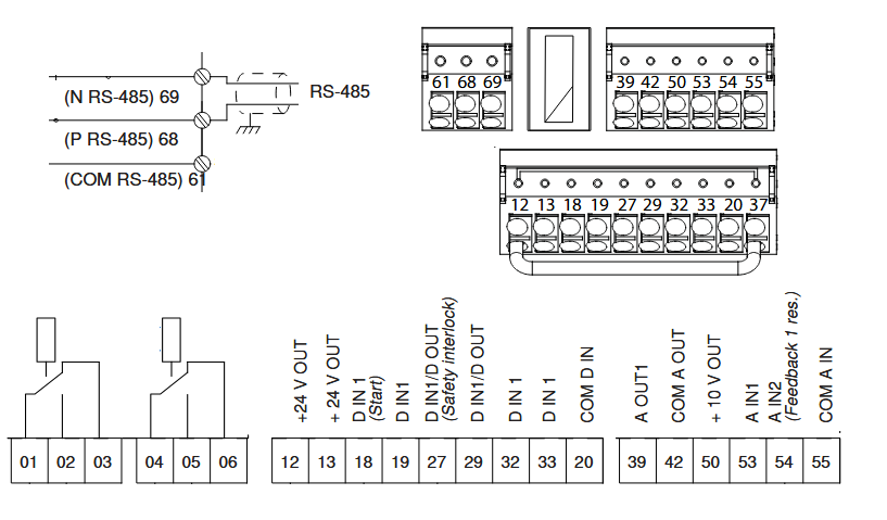
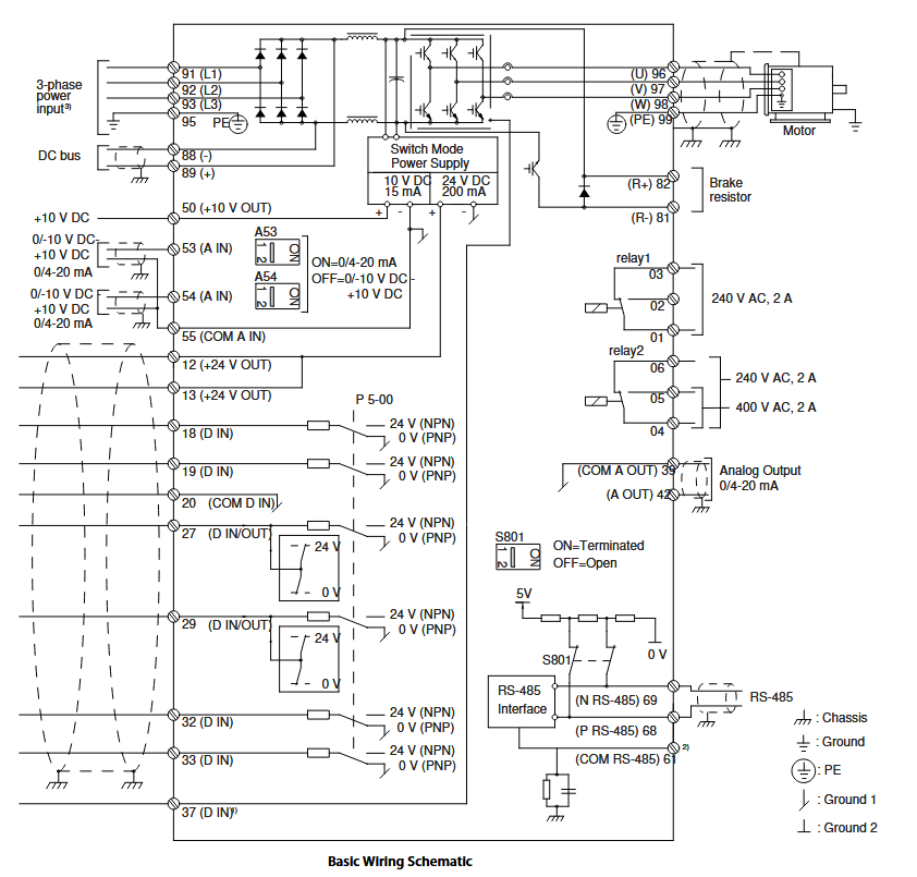
Wiring Details
Below image show terminal details:
Faults & Alarms
Search from below list for FC102 drive faults & alarms:
| Fault Code | Cause & Solution |
|---|---|
| Warning 1 10 Volts Low | Cause: The control card voltage is less than 10 V from terminal 50. Remove some of the load from terminal 50, as the 10 V supply is overloaded. Maximum 15 mA or minimum 590 Ω. – A short circuit in a connected potentiometer or incorrect wiring of the potentiometer can cause this condition. Troubleshooting: – Remove the wiring from terminal 50. – If the warning clears, the problem is with the wiring. If the warning does not clear, replace the control card. |
| WARNING 2 Live zero error | Cause: This warning or alarm only appears if programmed in parameter 6-01 Live Zero Timeout Function. The signal on 1 of the analog inputs is less than 50% of the minimum value programmed for that input. Broken wiring or faulty device sending the signal can cause this condition. Troubleshooting: 1. Check connections on all the analog input terminals. a. Control card terminals 53 and 54 for signals, terminal 55 common. b. VLT® General Purpose I/O MCB 101 terminals 11 and 12 for signals, terminal 10 common. c. VLT® Analog I/O Option MCB 109 terminals 1, 3, and 5 for signals, terminals 2, 4, and 6 common. Check that the drive programming and switch settings match the analog signal type. 2. Perform the input terminal signal test. |
| ALARM 2 Live zero error | Cause: This warning or alarm only appears if programmed in parameter 6-01 Live Zero Timeout Function. The signal on 1 of the analog inputs is less than 50% of the minimum value programmed for that input. Broken wiring or faulty device sending the signal can cause this condition. Troubleshooting: 1. Check connections on all the analog input terminals. a. Control card terminals 53 and 54 for signals, terminal 55 common. b. VLT® General Purpose I/O MCB 101 terminals 11 and 12 for signals, terminal 10 common. c. VLT® Analog I/O Option MCB 109 terminals 1, 3, and 5 for signals, terminals 2, 4, and 6 common. Check that the drive programming and switch settings match the analog signal type. 2. Perform the input terminal signal test. |
| WARNING 3 No motor | Cause: No motor is connected to the output of the frequency converter. Solution: – Check the cable connection between the frequency converter and the motor. |
| ALARM 3 No motor | Cause: No motor is connected to the output of the frequency converter. Solution: – Check the cable connection between the frequency converter and the motor. |
| WARNING 4 Mains phase loss | Cause: A phase is missing on the supply side, or the mains voltage imbalance is too high. This message also appears for a fault in the input rectifier on the frequency converter. Options are programmed at parameter 14-12 Function at Mains Imbalance. Troubleshooting: – Check the supply voltage and supply currents to the frequency converter. |
| ALARM 4 Mains phase loss | Cause: A phase is missing on the supply side, or the mains voltage imbalance is too high. This message also appears for a fault in the input rectifier on the frequency converter. Options are programmed at parameter 14-12 Function at Mains Imbalance. Troubleshooting: – Check the supply voltage and supply currents to the frequency converter. |
| Warning 5 DC Link Voltage High | Cause: The DC-link voltage (DC) is higher than the high-voltage warning limit. The limit depends on the drive voltage rating. The unit is still active. |
| WARNING 7 DC overvoltage | Cause: If the DC-link voltage exceeds the limit, the frequency converter trips after a time. Troubleshooting: – Extend the ramp time. – Change the ramp type. |
| ALARM 7 DC overvoltage | Cause: If the DC-link voltage exceeds the limit, the frequency converter trips after a time. Troubleshooting: – Extend the ramp time. – Change the ramp type. |
| WARNING 8 DC under voltage | Cause: If the DC-link voltage (DC) drops below the under voltage limit, the frequency converter trips after a fixed time delay. The time delay varies with unit size. Troubleshooting: – Check that the supply voltage matches the frequency converter voltage. – Perform an input voltage test. |
| ALARM 8 DC under voltage | Cause: If the DC-link voltage (DC) drops below the under voltage limit, the frequency converter trips after a fixed time delay. The time delay varies with unit size. Troubleshooting: – Check that the supply voltage matches the frequency converter voltage. – Perform an input voltage test. |
| WARNING 9 Inverter overload | Cause: The drive is about to cut out because of an overload (too high current for too long). The counter for electronic, thermal inverter protection issues a warning at 90% and trips at 100%, while giving an alarm. The drive cannot be reset until the counter is below 90%. The fault occurs when the drive has run with more than 100% overload for too long. Troubleshooting: – Compare the output current shown on the LCP with the drive rated current. – Compare the output current shown on the LCP with the measured motor current. – Show the thermal drive load on the LCP and monitor the value. When running above the drive continuous current rating, the counter increases. When running below the drive continuous current rating, the counter decreases. |
| ALARM 9 Inverter overload | Cause: The drive is about to cut out because of an overload (too high current for too long). The counter for electronic, thermal inverter protection issues a warning at 90% and trips at 100%, while giving an alarm. The drive cannot be reset until the counter is below 90%. The fault occurs when the drive has run with more than 100% overload for too long. Troubleshooting: – Compare the output current shown on the LCP with the drive rated current. – Compare the output current shown on the LCP with the measured motor current. – Show the thermal drive load on the LCP and monitor the value. When running above the drive continuous current rating, the counter increases. When running below the drive continuous current rating, the counter decreases. |
| WARNING 10 Motor ETR Overtemperature | Cause: According to the electronic thermal protection (ETR), the motor is too hot. Select whether the drive issues a warning or an alarm when the counter reaches 100% in parameter 1-90 Motor Thermal Protection. The fault occurs when the motor runs with more than 100% overload for too long. Troubleshooting: – Check for motor overheating. – Check if the motor is mechanically overloaded. – Check that the motor current set in parameter 1-24 Motor Current is correct. – Ensure that the motor data in parameter 1-20 to parameter 1-25 is set correctly. – Running AMA in parameter 1-29 Automatic Motor Adaptation (AMA) tunes the drive to the motor more accurately and reduces thermal loading. |
| ALARM 10 Motor ETR Overtemperature | Cause: According to the electronic thermal protection (ETR), the motor is too hot. Select whether the drive issues a warning or an alarm when the counter reaches 100% in parameter 1-90 Motor Thermal Protection. The fault occurs when the motor runs with more than 100% overload for too long. Troubleshooting: – Check for motor overheating. – Check if the motor is mechanically overloaded. – Check that the motor current set in parameter 1-24 Motor Current is correct. – Ensure that the motor data in parameter 1-20 to parameter 1-25 is set correctly. – Running AMA in parameter 1-29 Automatic Motor Adaptation (AMA) tunes the drive to the motor more accurately and reduces thermal loading. |
| WARNING 11 Motor thermistor over temp | Cause: Check whether the thermistor is disconnected. Select whether the drive issues a warning or an alarm in parameter 1-90 Motor Thermal Protection. Troubleshooting: – Check for motor overheating. – Check if the motor is mechanically overloaded. – When using terminal 53 or 54, check that the thermistor is connected correctly between either terminal 53 or 54 (analog voltage input) and terminal 50 (+10 V supply). Also check that the terminal switch for 53 or 54 is set for voltage. Check that parameter 1-93 Thermistor Resource selects terminal 53 or 54. – When using terminal 18, 19, 31, 32, or 33 (digital inputs), check that the thermistor is connected correctly between the digital input terminal used (digital input PNP only) and terminal 50. Select the terminal to use in parameter 1-93 Thermistor Resource. |
| ALARM 11 Motor thermistor over temp | Cause: Check whether the thermistor is disconnected. Select whether the drive issues a warning or an alarm in parameter 1-90 Motor Thermal Protection. Troubleshooting: – Check for motor overheating. – Check if the motor is mechanically overloaded. – When using terminal 53 or 54, check that the thermistor is connected correctly between either terminal 53 or 54 (analog voltage input) and terminal 50 (+10 V supply). Also check that the terminal switch for 53 or 54 is set for voltage. Check that parameter 1-93 Thermistor Resource selects terminal 53 or 54. – When using terminal 18, 19, 31, 32, or 33 (digital inputs), check that the thermistor is connected correctly between the digital input terminal used (digital input PNP only) and terminal 50. Select the terminal to use in parameter 1-93 Thermistor Resource. |
| WARNING 12 Torque Limit | Cause: The torque has exceeded the value in parameter 4-16 Torque Limit Motor Mode or the value in parameter 4-17 Torque Limit Generator Mode. Parameter 14-25 Trip Delay at Torque Limit can change this warning from a warning-only condition to a warning followed by an alarm. Troubleshooting: – If the motor torque limit is exceeded during ramp-up, extend the ramp-up time. – If the generator torque limit is exceeded during ramp-down, extend the ramp-down time. – If torque limit occurs while running, increase the torque limit. Make sure that the system can operate safely at a higher torque. – Check the application for excessive current draw on the motor. |
| ALARM 12 Torque Limit | Cause: The torque has exceeded the value in parameter 4-16 Torque Limit Motor Mode or the value in parameter 4-17 Torque Limit Generator Mode. Parameter 14-25 Trip Delay at Torque Limit can change this warning from a warning-only condition to a warning followed by an alarm. Troubleshooting: – If the motor torque limit is exceeded during ramp-up, extend the ramp-up time. – If the generator torque limit is exceeded during ramp-down, extend the ramp-down time. – If torque limit occurs while running, increase the torque limit. Make sure that the system can operate safely at a higher torque. – Check the application for excessive current draw on the motor. |
| WARNING 13 Over current | Cause: The inverter peak current limit (approximately 200% of the rated current) is exceeded. The warning lasts about 1.5 s, then the drive trips and issues an alarm. Shock loading or quick acceleration with high-inertia loads can cause this fault. If the acceleration during ramp-up is quick, the fault can also appear after kinetic backup. If extended mechanical brake control is selected, a trip can be reset externally. Troubleshooting: – Remove power and check if the motor shaft can be turned. – Check that the motor size matches the drive. – Check that the motor data is correct in parameters 1-20 to 1-25. |
| ALARM 13 Over current | Cause: The inverter peak current limit (approximately 200% of the rated current) is exceeded. The warning lasts about 1.5 s, then the drive trips and issues an alarm. Shock loading or quick acceleration with high-inertia loads can cause this fault. If the acceleration during ramp-up is quick, the fault can also appear after kinetic backup. If extended mechanical brake control is selected, a trip can be reset externally. Troubleshooting: – Remove power and check if the motor shaft can be turned. – Check that the motor size matches the drive. – Check that the motor data is correct in parameters 1-20 to 1-25. |
| ALARM 14 Earth (ground) fault | Cause: There is current from the output phase to ground, either in the cable between the drive and the motor, or in the motor itself. The current sensors detect the ground fault by measuring current going out from the drive and current going into the drive from the motor. Ground fault is issued if the deviation of the 2 currents is too large. The current going out of the drive must be the same as the current going into the drive. Troubleshooting: – Remove power to the drive and repair the ground fault. – Check for ground faults in the motor by measuring the resistance to ground of the motor cables and the motor with a megohmmeter. – Reset any potential individual offset in the 3 current sensors in the drive. Perform a manual initialization or perform a complete AMA. This method is most relevant after changing the power card. |
| Alarm 15 Hardware Mismatch | Cause: A fitted option is not operational with the present control card hardware or software. Troubleshooting: Record the values of the following parameters and contact . – a. Parameter 15-40 FC Type – b. Parameter 15-41 Power Section – c. Parameter 15-42 Voltage – d. Parameter 15-43 Software Version – e. Parameter 15-45 Actual Typecode String – f. Parameter 15-49 SW ID Control Card – g. Parameter 15-50 SW ID Power Card – h. Parameter 15-60 Option Mounted – i. Parameter 15-61 Option SW Version (for each option slot). |
| ALARM 16 Short circuit | Cause: There is short-circuiting in the motor or motor wiring. Solution: Remove power to the frequency converter and repair the short circuit. |
| WARNING 17 Control word timeout | Cause: There is no communication to the drive. The warning is only active when parameter 8-04 Control Word Timeout Function is NOT set to [0] Off. – If parameter 8-04 Control Word Timeout Function is set to [5] Stop and Trip, a warning appears. The drive then ramps down to stop and issues an alarm. Troubleshooting: – Check the connections on the serial communication cable. – Increase parameter 8-03 Control Word Timeout Time. – Check the operation of the communication equipment. – Verify that the installation adheres to the EMC requirements. |
| ALARM 17 Control word timeout | Cause: There is no communication to the drive. The warning is only active when parameter 8-04 Control Word Timeout Function is NOT set to [0] Off. – If parameter 8-04 Control Word Timeout Function is set to [5] Stop and Trip, a warning appears. The drive then ramps down to stop and issues an alarm. Troubleshooting: – Check the connections on the serial communication cable. – Increase parameter 8-03 Control Word Timeout Time. – Check the operation of the communication equipment. – Verify that the installation adheres to the EMC requirements. |
| WARNING 20 Temp. Input Error | Cause: The temperature detected by VLT® Sensor Input Option MCB 114 exceeds the limit. – This warning/alarm is only active when [5] Stop and trip is selected in parameter 35-06 Temperature Sensor Alarm Function. Troubleshooting: 1. Check the settings of the following parameters: – a. Parameter group 35-1* Temp. Input X48/4 – b. Parameter group 35-2* Temp. Input X48/7 – c. Parameter group 35-3* Temp. Input X48/10 2. Check the feedback temperature from the following parameters: – a. Parameter 18-37 Temp. Input X48/4 – b. Parameter 18-38 Temp. Input X48/7Programming Guide | VLT® HVAC Drive FC 102 |
| ALARM 20 Temp. Input Error | Cause: The temperature detected by VLT® Sensor Input Option MCB 114 exceeds the limit. – This warning/alarm is only active when [5] Stop and trip is selected in parameter 35-06 Temperature Sensor Alarm Function. Troubleshooting: 1. Check the settings of the following parameters: – a. Parameter group 35-1* Temp. Input X48/4 – b. Parameter group 35-2* Temp. Input X48/7 – c. Parameter group 35-3* Temp. Input X48/10 2. Check the feedback temperature from the following parameters: – a. Parameter 18-37 Temp. Input X48/4 – b. Parameter 18-38 Temp. Input X48/7 |
| Warning 23 Internal Fan Fault | Cause: The fan warning function is a protective function that checks if the fan is running/mounted. The fan warning can be disabled in parameter 14-53 Fan Monitor by selecting [0] Disabled. For drives with DC fans, a feedback sensor is mounted in the fan. If the fan is commanded to run and there is no feedback from the sensor, this warning appears. For drives with AC fans, the voltage to the fan is monitored. Troubleshooting: – Cycle for proper fan operation. – Cycle power to the drive and check that the fan operates briefly at start-up. – Check the sensors on the control card. |
| Warning 24 External Fan Fault | Cause: The fan warning function is a protective function that checks if the fan is running/mounted. The fan warning can be disabled in parameter 14-53 Fan Monitor by selecting [0] Disabled. For drives with DC fans, a feedback sensor is mounted in the fan. If the fan is commanded to run and there is no feedback from the sensor, this warning appears. For drives with AC fans, the voltage to the fan is monitored. Troubleshooting: – Check for proper fan operation. – Cycle power to the drive and check that the fan operates briefly at start-up. – Check the sensors on the heat sink. |
| Warning 22 Hoist Mechanical Brake | Cause: The value of this warning/alarm shows the type of warning/alarm. – 0 = The torque reference was not reached before timeout (parameter 2-27 Torque Ramp Up Time. – 1 = Expected brake feedback was not received before timeout (parameter 2-23 Activate Brake Delay, parameter 2-25 Brake Release Time. |
| Alarm 22 Hoist Mechanical Brake | Cause: The value of this warning/alarm shows the type of warning/alarm. – 0 = The torque reference was not reached before timeout (parameter 2-27 Torque Ramp Up Time. – 1 = Expected brake feedback was not received before timeout (parameter 2-23 Activate Brake Delay, parameter 2-25 Brake Release Time. |
| WARNING 25 Brake Resistor Short Circuit | Cause: The brake resistor is monitored during operation. If a short circuit occurs, the brake function is disabled, and the warning appears. The drive is still operational, but without the brake function. Troubleshooting: – Remove the power to the drive and replace the brake resistor (refer to parameter 2-15 Brake Check. |
| WARNING 26 Brake Resistor Power Limit | Cause: The power transmitted to the brake resistor is calculated as an average value over the last 120 s of run time. The calculation is based on the DC-link voltage and the brake resistor value set in parameter 2-16 Brake Max. Current. The warning is active when the dissipated braking power is higher than 90% of the brake resistor power. If [2] Trip is selected in parameter 2-13 Brake Power Monitoring, the drive trips when the dissipated braking power reached 100%. Troubleshooting: – Decrease brake energy via lower speed or longer ramp time. |
| ALARM 26 Brake Resistor Power Limit | Cause: The power transmitted to the brake resistor is calculated as an average value over the last 120 s of run time. The calculation is based on the DC-link voltage and the brake resistor value set in parameter 2-16 Brake Max. Current. The warning is active when the dissipated braking power is higher than 90% of the brake resistor power. If [2] Trip is selected in parameter 2-13 Brake Power Monitoring, the drive trips when the dissipated braking power reached 100%. Troubleshooting: – Decrease brake energy via lower speed or longer ramp time. |
| WARNING 27 Brake Chopper Fault | Cause: The brake transistor is monitored during operation. If a short circuit occurs, the brake function is disabled, and a warning is issued. The drive is still operational, but since the brake transistor has short-circuited, substantial power is transmitted to the brake resistor, even if it is inactive. Troubleshooting: – Remove the power to the drive, and remove the brake resistor. |
| ALARM 27 Brake Chopper Fault | Cause: The brake transistor is monitored during operation. If a short circuit occurs, the brake function is disabled, and a warning is issued. The drive is still operational, but since the brake transistor has short-circuited, substantial power is transmitted to the brake resistor, even if it is inactive. Troubleshooting: – Remove the power to the drive, and remove the brake resistor. |
| WARNING 28 Brake Check Failed | Cause: The brake resistor is not connected or not working. Troubleshooting: – Check parameter 2-15 Brake Check. |
| ALARM 28 Brake Check Failed | Cause: The brake resistor is not connected or not working. Troubleshooting: – Check parameter 2-15 Brake Check. |
| ALARM 29 Heat Sink Temp | Cause: The maximum temperature of the heat sink is exceeded. The temperature fault is not reset until the temperature drops below a defined heat sink temperature. The trip and reset points are different, based on the drive power size. Troubleshooting: Check for the following conditions: – The ambient temperature is too high. – The motor cables are too long. – Incorrect airflow clearance above and below the drive. – Blocked airflow around the drive. – Damaged heat sink fan. – Dirty heat sink. |
| ALARM 30 Motor phase U missing | Cause: Motor phase U between the frequency converter and the motor is missing. Solution: Remove power from the frequency converter and check motor phase U. |
| ALARM 31 Motor phase V missing | Cause: Motor phase V between the frequency converter and the motor is missing. Solution: Remove power from the frequency converter and check motor phase V. |
| ALARM 32 Motor phase W missing | Cause: Motor phase W between the frequency converter and the motor is missing. Solution: Remove power from the frequency converter and check motor phase W. |
| ALARM 33 Inrush Fault | Cause: Too many power-ups have occurred within a short time period. Troubleshooting: – Let the unit cool to operating temperature. – Check potential DC-link fault to ground. |
| WARNING 34 Fieldbus Fault | Cause: The fieldbus on the communication option card is not working. Troubleshooting: – Check the fieldbus communication option card. |
| ALARM 34 Fieldbus Fault | Cause: The fieldbus on the communication option card is not working. Troubleshooting: – Check the fieldbus communication option card. |
| ALARM 35 Option Fault | Cause: Fieldbus or option B detects internal faults. Troubleshooting: – There is an hardware or software issue in drive. Need to repair or replace drive. |
| WARNING 36 Mains Failure | Cause: This warning/alarm is only active if the supply voltage to the drive is lost and parameter 14-10 Mains Failure is not set to [0] No function. Troubleshooting: – Check the fuses to the drive and mains supply to the unit. |
| Alarm 36 Mains Failure | Cause: This warning/alarm is only active if the supply voltage to the drive is lost and parameter 14-10 Mains Failure is not set to [0] No function. Troubleshooting: – Check the fuses to the drive and mains supply to the unit. |
| ALARM 38 Internal Fault | Cause: When an internal fault occurs, a code number is shown. Below table Internal Fault List: – 0: The serial port cannot be initialized. Contact the Danfoss supplier or Danfoss service department. – 256–258: The power EEPROM data is defective or too old. Replace the power card. – 512–519: Internal fault. Contact the Danfoss supplier or Danfoss service department. – 783: Parameter value outside of the minimum/maximum limits. Adjust the parameter value to match the limits. – 1024–1284: Internal fault. Contact the Danfoss supplier or Danfoss service department. – 1299: The option software in slot A is too old. Upgrade the software in the drive to the latest version. – 1300: The option software in slot B is too old. Upgrade the software in the drive to the latest version. – 1302: The option software in slot C1 is too old. Upgrade the software in the drive to the latest version. – 1315: The option software in slot A is not sup- ported/allowed. The software version of the option or the fieldbus variant is not compatible with the drive software. – 1316: The option software in slot B is not sup- ported/allowed. The software version of the option or the fieldbus variant is not compatible with the drive software. – 1318: The option software in slot C1 is not sup- ported/allowed. The software version of the option or the fieldbus variant is not compatible with the drive software. – 1379–2819: Internal fault. Contact the Danfoss supplier or Danfoss service department. – 1792: Hardware reset of digital signal processor. – 1793: Motor-derived parameters not transferred correctly to the digital signal processor. – 1794: Power data not transferred correctly at power- up to the digital signal processor. – 1795 The digital signal processor has received too many unknown SPI telegrams. The AC drive also uses this fault code if the MCO does not power up correctly. Check for poor EMC protection and improper grounding. – 1796: RAM copy error. – 2561: Replace the control card. – 2820: LCP stack overflow. – 2821: Serial port overflow. – 2822: USB port overflow – 3072–5122: Parameter value is outside its limits. Adjust the parameter value to match the limits. – 5123: Option in slot A: Hardware incompatible with the control board hardware. Change either the fieldbus hardware or the control board hard- ware. – 5124: Option in slot B: Hardware incompatible with the control board hardware. Change either the fieldbus hardware or the control board hard- ware. – 5125: Option in slot C0: Hardware incompatible with the control board hardware. Change either the fieldbus hardware or the control board hard- ware. – 5126: Option in slot C1: Hardware incompatible with the control board hardware. Change either the fieldbus hardware or the control board hard- ware. – 5376–6231: Internal fault. Contact the Danfoss supplier or Danfoss service department. Troubleshooting – See the above table for the causes and solutions for different internal faults. If the fault persists, contact the supplier or service department for assistance. |
| ALARM 39 Heat Sink Sensor | Cause: There is no feedback from the heat sink temperature sensor. The signal from the IGBT thermal sensor is not available on the power card. Troubleshooting: – Check the ribbon cable between the power card and the gate drive card. – Check for a defective power card. – Check for a defective gate drive card. |
| WARNING 40 Overload T27 | Troubleshooting: – Check the load connected to terminal 27 or remove the short-circuit connection. – Check parameter 5-00 Digital I/O Mode and parameter 5-01 Terminal 27 Mode. |
| WARNING 41 Overload T29 | Troubleshooting: – Check the load connected to terminal 29 or remove the short-circuit connection. – Check parameter 5-00 Digital I/O Mode and parameter 5-02 Terminal 29 Mode. |
| WARNING 42 Ovrld X30/6-7 | Troubleshooting, X30/6: – Check the load connected to the terminal or remove the short-circuit connection. – Check parameter 5-32 Term X30/6 Digi Out (MCB 101)(VLT® General Purpose I/O MCB 101). Troubleshooting, X30/7: – Check the load connected to the terminal or remove the short-circuit connection. – Check parameter 5-33 Term X30/7 Digi Out (MCB 101)(VLT® General Purpose I/O MCB 101). |
| WARNING 43 Ext. Supply | Cause: VLT® Extended Relay Option MCB 113 is mounted without 24 V DC. Select 1 of the options in the troubleshooting list. Troubleshooting: – Connect a 24 V DC external supply. – Specify that no external supply is used via parameter 14-80 Option Supplied by External 24VDC set to [0] No. A change in parameter 14-80 Option Supplied by External 24VDC requires a power cycle. |
| ALARM 45 Earth (Ground) Fault 2 | Cause: A ground fault has occurred. Troubleshooting: – Check for proper grounding and loose connections. – Check for proper wire size. – Check the motor cables for short circuits or leakage currents. |
| ALARM 46 Power Card Supply | Cause: The supply on the power card is out of range. Another reason can be a defective heat sink fan. There are 3 supplies generated by the switch mode supply (SMPS) on the power card: – 24 V. – 5 V. – ±18 V. When powered with VLT® 24 V DC Supply MCB 107, only 24 V and 5 V supplies are monitored. When powered with 3-phase mains voltage, all 3 supplies are monitored. Troubleshooting: – Check for a defective power card. – Check for a defective control card. – Check for a defective option card. – If 24 V DC is used, verify proper supply power. – Check for a defective heat sink fan. |
| ALARM 47 24 V Supply Low | Cause: The 24 V DC is measured on the control card. It occurs when the detected voltage on terminal 12 is lower than 18 V. Troubleshooting: – Check the control card and the load connected. |
| ALARM 48 1.8 V Supply Low | Cause: The 1.8 V DC supply used on the control card is outside of the allowed limits. The supply is measured on the control card. Troubleshooting: – Check for a defective control card. – If an option is installed, check for overvoltage. |
| WARNING 49 SPEED LIMIT | Cause: The warning is shown when the speed is outside of the specified range in parameter 4-12 Motor Speed Low Limit [Hz] and parameter 4-14 Motor Speed High Limit [Hz]. Troubleshooting: – Check if the system ran outside of the speed range. – Check if parameter 4-12 Motor Speed Low Limit [Hz] and parameter 4-14 Motor Speed High Limit [Hz] are set correctly. |
| FAULT 50 AMA Calibration Failed | Solution: There is an hardware or software issue in drive. Need to repair or replace drive. |
| ALARM 51 AMA check Unom and Inom | Cause: The setting of motor voltage, motor current, and motor power is presumably wrong. Solution: Check the settings in parameter 1-20 to parameter 1-25. |
| ALARM 52 AMA low Inom | Cause: The motor current is too low. – Check the setting in parameter 1-24 Motor Current. |
| ALARM 53 AMA motor too big | Cause: The motor is too large for the AMA to be performed. Troubleshooting: – Check the settings in parameter group 1-2* Motor Data. |
| ALARM 54 AMA motor too small | Cause: The motor is too small for the AMA to be performed. Troubleshooting: – Check the settings in parameter group 1-2* Motor Data. |
| ALARM 55 AMA Parameter out of range | Cause: The parameter values found from the motor are outside the acceptable range. |
| ALARM 56 AMA interrupted by user | Cause: The AMA is interrupted. Troubleshooting – Re-run the AMA calibration. |
| ALARM 57 AMA timeout | Cause: Try to start the AMA again a number of times, until the AMA is performed. Note that repeated runs may heat the motor to a level where the resistance Rs and Rr are increased. In most cases, this is not critical. |
| ALARM 58 AMA internal fault | Cause: AMA internal fault. Solution: There is an hardware or software issue in drive. Need to repair or replace drive. |
| WARNING 59 Current limit | Cause: The current is higher than the value in parameter 4-18 Current Limit. Troubleshooting: – Ensure that the motor data in parameters 1-20 to 1-25 is set correctly. – Increase the current limit if necessary. Ensure that the system can operate safely at a higher limit. |
| ALARM 60 External interlock | Cause: A digital input signal indicates a fault condition external to the drive. An external interlock has commanded the drive to trip. Troubleshooting: – Clear the external fault condition. – To resume normal operation, apply 24 V DC to the terminal programmed for external interlock. – Reset the drive. |
| WARNING 61 Feedback Error | Cause: An error between calculated speed and speed measurement from feedback device. Troubleshooting: – Check the settings for warning/alarm/disabling in parameter 4-30 Motor Feedback Loss Function. – Set the tolerable error in parameter 4-31 Motor Feedback Speed Error. – Set the tolerable feedback loss time in parameter 4-32 Motor Feedback Loss Timeout. |
| ALARM 61 Feedback Error | Cause: An error between calculated speed and speed measurement from feedback device. Troubleshooting: – Check the settings for warning/alarm/disabling in parameter 4-30 Motor Feedback Loss Function. – Set the tolerable error in parameter 4-31 Motor Feedback Speed Error. – Set the tolerable feedback loss time in parameter 4-32 Motor Feedback Loss Timeout. |
| WARNING 62 Output Frequency Limit | Cause for Flux Mode: If the output frequency reaches the value set in parameter 4-19 Max Output Frequency, the drive issues a warning. The warning ceases when the output drops below the maximum limit. If the drive is unable to limit the frequency, it trips and issues an alarm. The latter may happen in the Flux mode if the drive loses control of the motor. Troubleshooting for Flux Mode: – Check the application for possible causes. The load torque could be too significant to drag the motor run to a high speed. – Increase the output frequency limit. Ensure that the system can operate safely at a higher output frequency. Cause for VVC TCL Mode: The output speed limit is reached, and the torque reference is derated. If the system is designed to reduce the speed by speed limit function, the warning only means that the speed limit is active. Troubleshooting for VVC TCL Mode: – The system speed exceeds the speed limit, in this case, adjust the system speed or adjust the speed limit. – If the speed limit function is used to control system speed, the warning can be ignored. |
| ALARM 62 Output Frequency Limit | Cause for Flux Mode: If the output frequency reaches the value set in parameter 4-19 Max Output Frequency, the drive issues a warning. The warning ceases when the output drops below the maximum limit. If the drive is unable to limit the frequency, it trips and issues an alarm. The latter may happen in the Flux mode if the drive loses control of the motor. Troubleshooting for Flux Mode: – Check the application for possible causes. The load torque could be too significant to drag the motor run to a high speed. – Increase the output frequency limit. Ensure that the system can operate safely at a higher output frequency. Cause for VVC TCL Mode: The output speed limit is reached, and the torque reference is derated. If the system is designed to reduce the speed by speed limit function, the warning only means that the speed limit is active. Troubleshooting for VVC TCL Mode: – The system speed exceeds the speed limit, in this case, adjust the system speed or adjust the speed limit. – If the speed limit function is used to control system speed, the warning can be ignored. |
| ALARM 63 Mechanical Brake Low | Cause: The actual motor current has not exceeded the release brake current within the start delay time window. |
| WARNING 64 VOLTAGE LIMIT | Cause: The load and speed combination demands a motor voltage higher than the actual DC-link voltage. Troubleshooting: – Check if the mains input is not high enough. – Check if the output frequency is too high above motor nominal frequency. |
| WARNING 65 Control card over temperature | Cause: The cutout temperature of the control card has exceeded the upper limit. Troubleshooting: – Check that the ambient operating temperature is within the limits. – Check the fan operation. – Check the control card. |
| ALARM 65 Control card over temperature | Cause: The cutout temperature of the control card has exceeded the upper limit. Troubleshooting: – Check that the ambient operating temperature is within the limits. – Check the fan operation. – Check the control card. |
| Warning 66 Heat Sink Temperature Low | Cause: The drive is too cold to operate. This warning is based on the temperature sensor in the IGBT module. Troubleshooting: – Increase the ambient temperature of the unit. – Supply a trickle amount of current to the drive whenever the motor is stopped by setting parameter 2-00 DC Hold/Preheat Current to 5% and parameter 1-80 Function at Stop. |
| ALARM 67 Option Module Configuration Has Changed | Cause: One or more options have either been added or removed since the last power-down. Troubleshooting: – Check that the configuration change is intentional and reset the unit. |
| ALARM 68 Safe Stop Activated | Cause: The Safe Torque Off (STO) has been activated. Troubleshooting: – To resume normal operation, apply 24 V DC to terminal 37, then send a reset signal via bus, digital I/O, or by pressing [Reset]. |
| ALARM 69 Power card temperature | Cause: The temperature on the power card is either too high or too low. Troubleshooting: – Ensure that the ambient operating temperature is within the limits. – Check if the filters are clogged. – Check the fan operation. – Check the power card. |
| ALARM 70 Illegal FC Configuration | Cause: The control card and power card are incompatible. Troubleshooting: – To check compatibility, contact the supplier with the type code from the unit nameplate and the part numbers on the cards |
| ALARM 71 PTC 1 Safe Stop | Cause: Because the motor is too warm, the VLT® PTC Thermistor Card MCB 112 activated Safe Torque Off (STO). Troubleshooting Once the motor temperature reaches an acceptable level, and the digital input from MCB 112 is deactivated, perform 1 of the following: – Send a reset signal via bus or digital I/O. – Press [Reset]. |
| ALARM 72 Dangerous Failure | Cause: Safe Torque Off (STO) with trip lock. An unexpected combination of STO commands has occurred. Troubleshooting: – VLT® PTC Thermistor Card MCB 112 enables X44/10, but STO is not enabled. – MCB 112 is the only device using STO (specified via [4] PTC 1 alarm or [5] PTC 12 warning in parameter 5-19 Terminal 37 Safe Stop). STO is activated, but X44/10 is not. |
| WARNING 73 Safe Stop Auto Restart | Cause: STO is activated. Troubleshooting: – With automatic restart enabled, the motor can start when the fault is cleared. |
| WARNING 76 Power Unit Setup | Cause: The required number of power units does not match the detected number of active power units. Troubleshooting: – When replacing a drive module, this warning can occur if the power-specific data in the module power card does not match the rest of the drive. Confirm that the spare part and its power card are the correct code number. |
| WARNING 77 Reduced Power Mode | Cause: The drive is operating in reduced power mode (less than allowed number of inverter sections). The warning is generated on power cycle when the drive is set to run with fewer inverters and remains on. |
| ALARM 79 Illegal Power Section Configuration | Cause: The scaling card has an incorrect code number or is not installed. The MK102 connector on the power card could not be installed. |
| ALARM 80 Drive Initialized to Default Value | Cause: Parameter settings are initialized to default settings after a manual reset. Troubleshooting: – To clear the alarm, reset the unit. |
| ALARM 81 CSIV Corrupt | Cause: The CSIV file has syntax errors. |
| ALARM 82 CSIV Parameter Error | Cause: CSIV failed to initialize a parameter. |
| ALARM 88 Option Detection | Cause: A new option configuration has been detected. Troubleshooting: – Set parameter 14-89 Option Detection to [1] Enable Option Change, and power cycle the drive to accept the new configuration. |
| WARNING 90 Feedback Monitor | Cause: A feedback fault is detected by option B. |
| ALARM 90 Feedback Monitor | Cause: A feedback fault is detected by option B. |
| ALARM 91 Analog Input 54 Wrong Settings | Troubleshooting: – Set switch S202 in position OFF (voltage input) when a KTY sensor is connected to analog input terminal 54. |
| WARNING 92 No Flow | Cause: A no-flow condition has been detected in the system. Parameter 22-23 No-Flow Function is set for alarm. Troubleshooting: – Troubleshoot the system and reset the drive after the fault has been cleared. |
| ALARM 92 No Flow | Cause: A no-flow condition has been detected in the system. Parameter 22-23 No-Flow Function is set for alarm. Troubleshooting: – Troubleshoot the system and reset the drive after the fault has been cleared. |
| WARNING 93 Dry Pump | Cause: A no-flow condition in the system with the drive operating at high speed may indicate a dry pump. Parameter 22-26 Dry Pump Function is set for warning or alarm. Troubleshooting: – Troubleshoot the system. – Reset the drive when the fault is cleared. |
| ALARM 93 Dry Pump | Cause: A no-flow condition in the system with the drive operating at high speed may indicate a dry pump. Parameter 22-26 Dry Pump Function is set for warning or alarm. Troubleshooting: – Troubleshoot the system. – Reset the drive when the fault is cleared. |
| WARNING 94 End of Curve | Cause: Feedback is lower than the set point. This may indicate a leakage in the system. Parameter 22-50 End of Curve Function is set for warning or alarm. Troubleshooting: – Troubleshoot the system. – Reset the drive when the fault is cleared. |
| ALARM 94 End of Curve | Cause: Feedback is lower than the set point. This may indicate a leakage in the system. Parameter 22-50 End of Curve Function is set for warning or alarm. Troubleshooting: – Troubleshoot the system. – Reset the drive when the fault is cleared. |
| WARNING 95 Broken Belt | Cause: Torque is below the torque level set for no load, indicating a broken belt. Parameter 22-60 Broken Belt Function is set for alarm. Troubleshooting: -Troubleshoot the system and reset the drive after clearing the fault. |
| ALARM 95 Broken Belt | Cause: Torque is below the torque level set for no load, indicating a broken belt. Parameter 22-60 Broken Belt Function is set for alarm. Troubleshooting: -Troubleshoot the system and reset the drive after clearing the fault. |
| WARNING 96 Start Delayed | Cause: Motor start has been delayed due to short-cycle protection. Parameter 22-76 Inverval between Starts is enabled. Troubleshooting: – Troubleshoot the system. Reset the drive when the fault is cleared. |
| WARNING 97 Stop Delayed | Cause: Stopping the motor has been delayed due to short-cycle protection. Parameter 22-76 Interval between Starts is enabled. Troubleshooting: – Troubleshoot the system. – Reset the drive when the fault is cleared. |
| WARNING 98 Clock Fault | Cause: Time is not set or the RTC clock has failed. Troubleshooting: – Reset the clock in parameter 0-70 Date and Time. |
| ALARM 99 Locked Rotor | Cause: The rotor is blocked. It is only enabled for PM motor control. Troubleshooting: – Check if the motor shaft is locked. – Check if the start current triggers the current limit set in parameter 4-18 Current Limit. – Check if it increases the value in parameter 30-23 Locked Rotor Detection Time [s]. |
| WARNING 104 Mixing Fan Fault | Cause: The fan is not operating. The fan monitor checks that the fan is spinning at power-up or whenever the mixing fan is turned on. The mixing fan fault can be configured as a warning or an alarm in parameter 14-53 Fan Monitor. Troubleshooting: – Cycle power to the drive to determine if the warning/alarm returns. |
| ALARM 104 Mixing Fan Fault | Cause: The fan is not operating. The fan monitor checks that the fan is spinning at power-up or whenever the mixing fan is turned on. The mixing fan fault can be configured as a warning or an alarm in parameter 14-53 Fan Monitor. Troubleshooting: – Cycle power to the drive to determine if the warning/alarm returns. |
| WARNING 122 Mot. Rotat. Unexp. | Cause: The drive performs a function that requires the motor to be at a standstill, for example, DC hold for PM motors. |
| ALARM 122, Mot. Rotat. Unexp. | Cause: The drive performs a function that requires the motor to be at a standstill, for example, DC hold for PM motors. |
| ALARM 144 Inrush Supply | Cause: A supply voltage on the inrush card is out of range. Troubleshooting: See the bit field result report value for more details. – a. Bit 2: Vcc high – b. Bit 3: Vcc low – c. Bit 4: Vdd high – d. Bit 5: Vdd low |
| ALARM 145 External SCR Disable | Cause: The alarm indicates a series DC-link capacitor voltage imbalance. |
| WARNING 146 Mains Voltage | Cause: Mains voltage is outside valid operating range. Troubleshooting: See the following report values for details. – a. Voltage too low: 0=R-S, 1=S-T, 2=T-R – b. Voltage too high: 3=R-S, 4=S-T, 5=T-R |
| ALARM 146 Mains Voltage | Cause: Mains voltage is outside valid operating range. Troubleshooting: See the following report values for details. – a. Voltage too low: 0=R-S, 1=S-T, 2=T-R – b. Voltage too high: 3=R-S, 4=S-T, 5=T-R |
| WARNING 147 Mains Frequency | Cause: Mains frequency is outside valid operating range. Troubleshooting: The following report values provide more information: – a. 0: frequency too low – b. 1: frequency too high |
| ALARM 147 Mains Frequency | Cause: Mains frequency is outside valid operating range. Troubleshooting: The following report values provide more information: – a. 0: frequency too low – b. 1: frequency too high |
| WARNING 148 System Temp | Cause: One or more of the system temperature measurements is too high. |
| ALARM 148 System Temp | Cause: One or more of the system temperature measurements is too high. |
| WARNING 154, D.out Overload | Cause: A digital output is overloaded. |
| ALARM 154 D.out Overload | Cause: A digital output is overloaded. |
| WARNING 163 ATEX ETR Cur.Lim. Warning | Cause: The drive has run above the characteristic curve for more than 50 s. The warning is activated at 83% and deactivated at 65% of the allowed thermal overload. |
| Alarm 164 ATEX ETR Cur.Lim. Alarm | Cause: Running above the characteristic curve for more than 60 s within a period of 600 s activated the alarm, and the drive trips. |
| WARNING 165 ATEX ETR Freq.Lim. Warning | Cause: The drive has run for more than 50 s below the allowed minimum frequency as set in parameter 1-98 ATEX ETR Interpol. Points.Freq.). |
| ALARM 166 ATEX ETR Freq.Lim. Alarm | Cause: The drive has run for more than 60 s in a period of 600 s below the allowed minimum frequency as set in parameter 1-98 ATEX ETR Interpol. Points. Freq.). |
| WARNING 200 Fire Mode | Cause: Fire mode has been activated. Troubleshooting: – The warning clears when fire mode is removed. – See the fire mode data in the alarm log. |
| WARNING 201 Fire Mode was Active | Troubleshooting: – Cycle power to the unit to remove the warning. See the fire mode data in the alarm log. |
| WARNING 202 Fire Mode Limits Exceeded | Cause: Fire mode has suppressed 1 or more warranty-voiding alarms. Troubleshooting: -Cycle power to the unit to remove the warning. – See the fire mode data in the alarm log. |
| WARNING 202 Fire Mode Limits Exceeded | Cause: While operating in fire mode, 1 or more alarm conditions have been ignored, which would normally trip the unit. Operating in this condition voids the warranty of the unit. Troubleshooting: – Cycle power to the unit to remove this warning. See the fire mode data in the alarm log. |
| WARNING 203 Missing Motor | Cause: A multi-motor underload situation is detected. This warning indicates that a motor is missing. Troubleshooting: – Inspect the system for proper operation. |
| WARNING 204 Locked Rotor | Cause: An overload condition is detected for a drive operating multi-motors. This warning indicates that there is a locked rotor. Troubleshooting: – Inspect that the motor operates properly. |
| WARNING 220 Configuration File Version not Supported | Cause: The drive does not support the current configuration file version. Customization is aborted. |
| ALARM 243 Brake IGBT | Cause: This alarm is only for multi-drive systems. It is equivalent to alarm 27, Brake chopper fault. The report value in thie alarm log indicates which drive module generated the alarm. This IGBT fault can be caused by any of the following: – The DC fuse is blown. – The brake jumper is not in position. – The Klixon switch opened due to an overtemperature condition in the brake resistor. Indication of the drive module generating the alarm: – 1 = Left drive module. – 2 = Second drive module from left. – 3 = Third drive module from left (in 4-module systems). – 4 = Fourth drive module from left (in 4-module systems). |
| ALARM 244 Heat Sink Temperature | Cause: The maximum temperature of the heat sink has been exceeded. The temperature fault cannot reset until the temperature drops below the defined heat sink temperature. The trip and reset points are different, based on the power size. This alarm is equivalent to Alarm 29, Power module temp. Troubleshooting: Check for the following: – a. Ambient temperature too high. – b. Motor cables too long. – c. Incorrect airflow clearance above or below the AC drive. – d. Blocked airflow around the unit. – e. Damaged heat sink fan. – f. Dirty heat sink. |
| ALARM 245 Heat Sink Sensor | Cause: There is no feedback from the heat sink temperature sensor. This signal form the IGBT thermal sensor is not available on the power card. – This alarm is equivalent to Alarm 39, Heat sink sensor. The report value in the alarm log indicates which drive module generated the alarm: – 1 = Left drive module. – 2 = Second drive module from the left. – 3 = Third drive module from the left (in 4-module systems). – 4 = Fourth drive module from the left (in 4-module systems). Troubleshooting: – Check the power card. – Check the gate drive card. – Check the ribbon cable between the power card and the gate drive card. |
| ALARM 246 Power Card Supply | Cause: The supply on the power card is out of range. This alarm is only for multi-drive systems. It is equivalent to Alarm 46, Power card supply. The report value in the alarm log indicates which drive module generated the alarm: – 1 = Left drive module. – 2 = Second drive module from left. – 3 = Third drive module from left (in 4-module systems). – 4 = Fourth drive module from left (in 4-module systems). |
| ALARM 247 Power Card Temperature | Cause: This alarm is only for multi-drive systems. It is equivalent to Alarm 69, Power card temperature. The report value in the alarm log indicates which drive module generated the alarm: – 1 = Left drive module. – 2 = Second drive module from left. – 3 = Third drive module from left (in 4-module systems). – 4 = Fourth drive module from left (in 4-module systems). |
| ALARM 248 Illegal Power Section Configuration | Cause: This alarm is only for multi-drive systems. It is equivalent to Alarm 79, Illegal power section configuration. The report value in the alarm log indicates which drive module generated the alarm: – 1 = Left drive module. – 2 = Second drive module from left. – 3 = Third drive module from left (in 4-module systems). – 4 = Fourth drive module from left (in 4-module systems). Troubleshooting: – Check the current scaling cards on the MDCIC. |
| WARNING 249 Rect. Low Temperature | Cause: The temperature of the rectifier heat sink is too low, which indicates that the temperature sensor may be detect. |
| WARNING 250 New Spare Part | Cause: A component in the drive system has been replaced. Troubleshooting: – Enter the serial number and type code for canceling the trip lock status after a power cycle. |
| WARNING 251 New Typecode | Cause: The power card or other components have been replaced, and the type code has changed. Troubleshooting: – Reset the drive for normal operation. |
| ALARM 421 FPC Temp | Cause: A fault caused by the on-board temperature sensor is detected on the fan power card. The report values identify which fan power card detected the fault. Troubleshooting: – Check the wiring. – Check the on-board temperature sensor. – Replace the fan power card. |
| ALARM 423 FPC Updating | Cause: The alarm is generated when the fan power card reports that it has an invalid PUD. The control card attempts to update the PUD. A subsequent alarm can result depending on the update. See Alarm 424, FPC Update Successul and Alarm 425, FPC Update Failure. |
| ALARM 424 FPC Update Successful | Cause: This alarm is generated when the control card has updated the fan power card PUD successfully. Troubleshooting: – Press [Reset] to stop the alarm. |
| ALARM 425 FPC Update Failure | Cause: This alarm is generated after the control card failed to update the fan power card PUD. Troubleshooting: – Check the fan power card wiring. – Replace the fan power card. |
| ALARM 426 FPC Config | Cause: The number of found fan power cards does not match the number of configured fan power cards. See parameter group 15-6* Option Ident for the number of configured fan power cards. Troubleshooting: – Check fan power card wiring. – Replace the fan power card. |
| ALARM 427 FPC Supply | Cause: Supply voltage faults (5 V, 24 V, or 48 V) on the fan power card is detected. Troubleshooting: – Check fan power card wiring. – Replace the fan power card. |
| ALARM 432 Inrush Mode Error | Cause: An active inrush card reported the wrong mode. The report value indicates which inrush card reported the alarm. Troubleshooting: – Check inrush card wiring. – Replace the inrush card. |
| Warning 500 Motor Stator Winding Warning 2 | Cause: The stator winding reached condition orange. A severe fault might occur soon in the motor. Troubleshooting: – Check the stator windings. |
| Warning 501 Load Envelope Warning 2 | Cause: Application load has reached condition yellow. Troubleshooting: – Investigate the root cause for the increased motor load. |
| Warning 502 Vibration Monitoring Warning 2 | Cause: A significant increase in motor vibration is detected. The vibration levels have reached condition orange. Troubleshooting: – Investigate the root cause for severe vibration. |
| Warning 506 Load Envelope Low Warning 2 | Cause: The application load has reached condition orange low limit. Troubleshooting: – Investigate the root cause for the decrease in motor load and then check the load specified for the application. |
| ALARM 510 Motor Stator Winding Alarm | Cause: Stator winding has reached condition red. A severe fault is detected in the motor. Troubleshooting: – Check motor stator winding. |
| WARNING 510 Motor Stator Winding Warning 1 | Cause: Stator winding reached condition yellow. An early fault is detected in the motor. Troubleshooting: – Check the motor stator winding. |
| ALARM 511 Load Envelope Alarm | Cause: Application load has reached condition red. Troubleshooting: – Check root cause for excessive overload or underload. |
| WARNING 511 Load Envelope Warning 1 | Cause: Application load has reached condition yellow. Troubleshooting: – Check root cause for high motor load. |
| Alarm 512 Sensor 1 Monitoring Alarm | Cause: There is an excessive amount of motor vibration on sensor 1. The vibration levels have reached condition red. Troubleshooting: – Investigate the root cause for the excessive vibration. Before commissioning of condition-based monitoring, ensure to comply with the ISO10816 standard for machinery. |
| Warning 512 Sensor 1 Monitoring Warning 1 | Cause: An increase in the Sensor 1 value is detected. The value levels in Sensor 1 have reached condition yellow. Troubleshooting: – Investigate the root cause for the increased values. |
| Alarm 513 Sensor 2 Monitoring Warning 1 | Cause: There is an excessive amount of motor vibration on sensor 2. The vibration levels have reached condition red. Troubleshooting: – Investigate the root cause for the excessive vibration. Before commissioning of condition-based monitoring, ensure to comply with the ISO10816 standard for machinery. |
| Warning 513 Sensor 2 Monitoring Warning 1 | Cause: An increase in the Sensor 2 value is detected. The value levels in Sensor 2 have reached condition yellow. Troubleshooting: – Investigate the root cause for the increased values. |
| Alarm 514 Sensor 3 Monitoring Alarm | Cause: There is an excessive amount of motor vibration on sensor 3. The vibration levels have reached condition red. Troubleshooting: – Investigate the root cause for the excessive vibration. Before commissioning of condition-based monitoring, ensure to comply with the ISO10816 standard for machinery. |
| Warning 514 Sensor 3 Monitoring Warning 1 | Cause: An increase in the Sensor 3 value is detected. The value levels in Sensor 3 have reached condition yellow. Troubleshooting: – Investigate the root cause for the increased values. |
| Alarm 515 Sensor 4 Monitoring Alarm | Cause: There is an excessive amount of motor vibration on sensor 4. The vibration levels have reached condition red. Troubleshooting: – Investigate the root cause for the excessive vibration. Before commissioning of condition-based monitoring, ensure to comply with the ISO10816 standard for machinery. |
| Warning 515 Sensor 4 Monitoring Warning 1 | Cause: An increase in the Sensor 4 value is detected. The value levels in Sensor 4 have reached condition yellow. Troubleshooting: – Investigate the root cause for the increased values. |
| Alarm 516 Load Envelope Low Alarm | Cause: The application load has reached low-level condition red. Troubleshooting: – Investigate the root cause for the decrease in motor load and then check the load specified for the application. |
| Warning 516 Load Envelope Low Warning 1 | Cause: The application load has reached low-level condition yellow. Troubleshooting: – Investigate the root cause for the decrease in motor load and then check the load specified for the application. |
| Warning 520 Stator Thld At Max/Min | Cause: The stator in the condition-based monitoring is either at its minimum or maximum limit. Troubleshooting: – Check the threshold values at maximum or minimum in parameter group 46-** CBM Adv Thresholds to parameter group 46-2* Stator and adjust the values if needed. – Acknowledge the generation by setting parameter 45-46 Threshold Limit to [0] Limit OK. |
| Warning 521 Load Thld At Max/Min | Cause: The load threshold in the condition-based monitoring is either at its minimum or maximum. Troubleshooting: – Check the threshold values at maximum or minimum in parameter group 46-** CBM Adv Thresholds to parameter group 46-3* Load and adjust the values if needed. – Acknowledge the generation by setting parameter 45-46 Threshold Limit to [0] Limit OK. |
| Warning 522 Sensor 1 Thld At Max/Min | Cause: The sensor 1 threshold in the condition-based monitoring is at its minimum or maximum value of the Sensor 1 function. Troubleshooting: – Check the threshold values at maximum or minimum in parameter group 46-** CBM Adv Thresholds to parameter group 46-4* Sensor 1 and adjust the values if needed. – Acknowledge the generation by setting parameter 45-46 Threshold Limit to [0] Limit OK. |
| Warning 523 Sensor 2 Thld At Max/Min | Cause: The sensor 2 threshold in the condition-based monitoring is at its minimum or maximum value of the Sensor 2 function. Troubleshooting: – Check the threshold values at maximum or minimum in parameter group 46-** CBM Adv Thresholds to parameter group 46-5* Sensor 2 and adjust the values if needed. – Acknowledge the generation by setting parameter 45-46 Threshold Limit to [0] Limit OK. |
| Warning 524 Sensor 3 Thld At Max/Min | Cause: The sensor 3 threshold in the condition-based monitoring is at its minimum or maximum value of the Sensor 3 function. Troubleshooting: – Check the threshold values at maximum or minimum in parameter group 46-** CBM Adv Thresholds to parameter group 46-6* Sensor 3 and adjust the values if needed. – Acknowledge the generation by setting parameter 45-46 Threshold Limit to [0] Limit OK. |
| Warning 525 Sensor 4 Thld At Max/Min | Cause: The sensor 4 threshold in the condition-based monitoring is at its minimum or maximum value of the Sensor 4 function. Troubleshooting: – Check the threshold values at maximum or minimum in parameter group 46-** CBM Adv Thresholds to parameter group 46-7* Sensor 4 and adjust the values if needed. – Acknowledge the generation by setting parameter 45-46 Threshold Limit to [0] Limit OK. |
| Alarm 550 Sensor 1 Low Monitoring Alarm | Cause: The value measured on Sensor 1 is very low and has reached condition red low. Troubleshooting: – Investigate the root cause for the value reaching the red low level. For example, lost connection to analog inputs or no proper data communication on fieldbus sensors. |
| Warning 550 Sensor 1 Low Monitoring Warning 1 | Cause: The value measured on Sensor 1 is very low and has reached condition yellow low. Troubleshooting: – Investigate the root cause for the value reaching the red low level. For example, lost connection to analog inputs or no proper data communication on fieldbus sensors. |
| Alarm 551 Sensor 2 Low Monitoring Alarm | Cause: The value measured on Sensor 2 is very low and has reached condition red low. Troubleshooting: – Investigate the root cause for the value reaching the red low level. For example, lost connection to analog inputs or no proper data communication on fieldbus sensors. |
| Warning 551 Sensor 2 Low Monitoring Warning 1 | Cause: The value measured on Sensor 2 is very low and has reached condition yellow low. Troubleshooting: – Investigate the root cause for the value reaching the red low level. For example, lost connection to analog inputs or no proper data communication on fieldbus sensors. |
| Alarm 552 Sensor 3 Low Monitoring Alarm | Cause: The value measured on Sensor 3 is very low and has reached condition red low. Troubleshooting: – Investigate the root cause for the value reaching the red low level. For example, lost connection to analog inputs or no proper data communication on fieldbus sensors. |
| Warning 552 Sensor 3 Low Monitoring Warning 1 | Cause: The value measured on Sensor 3 is very low and has reached condition yellow low. Troubleshooting: – Investigate the root cause for the value reaching the red low level. For example, lost connection to analog inputs or no proper data communication on fieldbus sensors. |
| Alarm 553 Sensor 4 Low Monitoring Alarm | Cause: The value measured on Sensor 4 is very low and has reached condition red low. Troubleshooting: – Investigate the root cause for the value reaching the red low level. For example, lost connection to analog inputs or no proper data communication on fieldbus sensors. |
| Warning 553 Sensor 4 Low Monitoring Warning 1 | Cause: The value measured on Sensor 4 is very low and has reached condition yellow low. Troubleshooting: – Investigate the root cause for the value reaching the red low level. For example, lost connection to analog inputs or no proper data communication on fieldbus sensors. |