Download Links
 Download Catalog Download Catalog |
Download Manual |
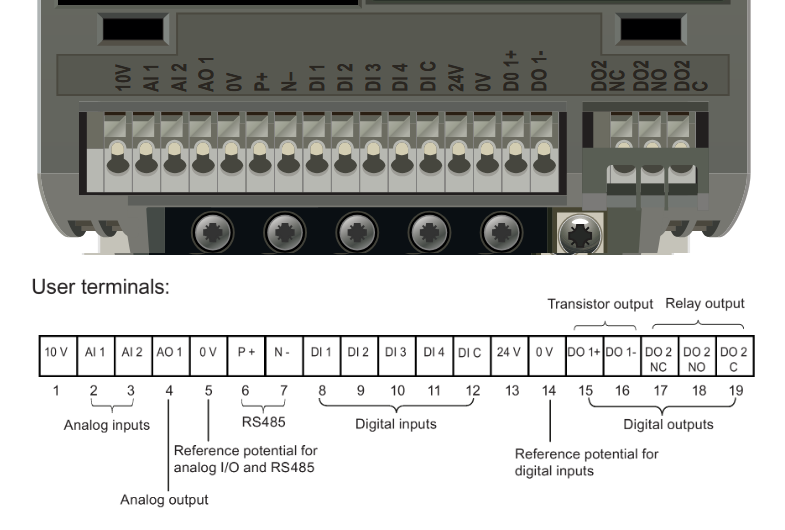
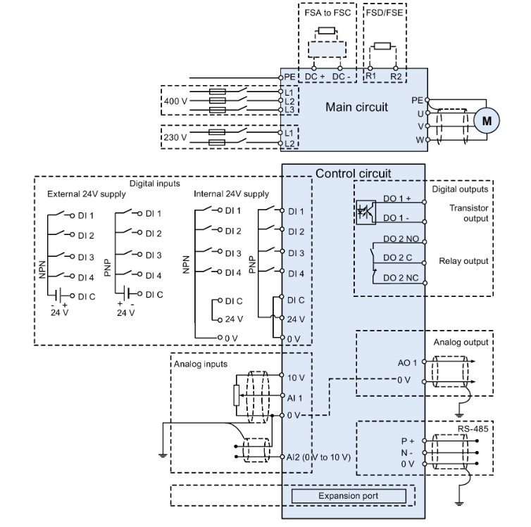
Wiring Details
Below image show terminal details:
Faults & Alarms
Search from below list for V20 drive faults & alarms:
| Fault Codes | Cause & Solution |
|---|---|
| F1 Overcurrent | Cause: • Motor power (P0307) does not correspond to the inverter power (r0206). • Motor lead short circuit • Earth faults – r0949 = 0: Hardware reported – r0949 = 1: Software reported – r0949 = 22: Hardware reported Soultion: Check the following: • Motor power (P0307) must correspond to in-verter power (r0206). • Cable length limits must not be exceeded. • Motor cable and motor must have no short- circuits or earth faults. • Motor parameters must match the motor in use. • Value of stator resistance (P0350) must be correct. • Motor must not be obstructed or overloaded. • Increase ramp-up time (P1120) • Reduce starting boost level (P1312) |
| F2 Overvoltage | Cause: • Main supply voltage too high • Motor is in regenerative mode – r0949 = 0: Hardware reported – r0949 = 1 or 2: Software reported Soultion: Check the following: • Supply voltage (P0210) must lie within limits indicated on rating plate. • Ramp-down time (P1121) must match inertia of load. • Required braking power must lie within specified limits. • Vdc controller must be enabled (P1240) and parameterized properly. Note: Regenerative mode can be caused by fast ramp downs or if the motor is driven by an active load. Higher inertia requires longer ramp times; other- wise, apply braking resistor. |
| F3 Undervoltage | Cause: • Main supply failed. • Shock load outside specified limits. – r0949 = 0: Hardware reported – r0949 = 1 or 2: Software reported Soultion: 1. Check supply voltage. 2. Check drive rectifier section using multimeter. |
| F4 Inverter overtemperature | Cause: • Inverter overloaded • Ventilation inadequate • Pulse frequency too high • Surrounding temperature too high • Fan inoperative Soultion: Check the following: • Load or load cycle too high? • Motor power (P0307) must match inverter power (r0206) • Pulse frequency must be set to default value • Surrounding temperature too high? • Fan must turn when inverter is running |
| F5 Inverter I2t | Cause: • Inverter overloaded. • Load cycle too demanding. • Motor power (P0307) exceeds in- verter power capability (r0206). Soultion: Check the following: • Load cycle must lie within specified limits. • Motor power (P0307) must match inverter power (r0206) Note: F5 cannot be cleared until the inverter over- load utilization (r0036) is lower than the inverter I2 t warning (P0294). |
| F6 Chip temperature rise exceeds critical levels | Cause: • Load at start-up is too high • Load step is too high • Ramp-up rate is too fast Soultion: Check the following: • Load or load step too high? • Increase ramp-up time (P1120). • Motor power (P0307) must match inverter power (r0206). • Use setting P0290 = 0 or 2 for preventing F6. |
| F11 Motor overtemperature | Cause 1: Motor overloaded Soultion: Check the following: • Load or load step too high? • Motor nominal overtemperatures (P0626 – P0628) must be correct • Motor temperature warning level (P0604) must match Cause 2: This fault may occur if small motors (≤ 250 W, 4- or 2-pole) are used and run at a frequency below 15 Hz, even though the motor temperature is within limits. Soultion: Check the following: • Motor current is not in excess of the motor nominal current as indicated by the motor rating plate • Physical temperature of the motor lies within limits If these two conditions are satisfied, then set pa- rameter P0335 = 1. |
| F12 Inverter temperature signal lost | Cause: Wire breakage of inverter temperature (heat sink) sensor. Soultion: There is an hardware or software issue in drive. Need to repair or replace drive. |
| F20 DC ripple too high | Cause: The calculated DC ripple level has exceeded the safe threshold. This is commonly caused by loss of one of the mains input phases. Soultion: 1. Check the mains supply wiring. 2. There is an hardware or software issue in drive. Need to repair or replace drive. |
| F35 Maximum number of auto restart attempts exceeded | Cause: Auto restart attempts exceed value of P1211. |
| F41 Motor data identification failure | Cause: Motor data identification failed. • r0949 = 0: No load applied • r0949 = 1: Current limit level reached during identification. • r0949 = 2: Identified stator resistance less than 0.1% or greater than 100%. • r0949 = 30: Current controller at voltage limit • r0949 = 40: Inconsistency of identi- fied dataset, at least one identifica- tion failed Percentage values based on the im- pedance Zb = Vmot,nom / sqrt(3) / Imot,nom Soultion: Check the following: • r0949 = 0: is the motor connected to the inverter? • r0949 = 1 – 49: are the motor data in P0304 – P0311 correct? • Check what type of motor wiring is required (star, delta). |
| F51 Parameter EEPROM fault | Cause: Read or write failure while access to EEPROM. This can also be caused by the EEPROM being full, too many parameters have been changed. Soultion: • Must be power-cycled to cancel this bug as some parameters may not be read correct. • Factory reset and new parameterization, if power-cycle does not remove fault. • Change some parameters back to default val- ues if the EEPROM is full, then power-cycle. • Change inverter. Note: • r0949 = 1: EEPROM full • r0949 = 1000 + block No: reading data block failed • r0949 = 2000 + block No: reading data block timeout • r0949 = 3000 + block No: reading data block CRC failed • r0949 = 4000 + block No: writing data block failed • r0949 = 5000 + block No: writing data block timeout • r0949 = 6000 + block No: writing data block verify failed • r0949 = 7000 + block No: reading data block at wrong time • r0949 = 8000 + block No: writing data block at wrong time • r0949 = 9000 + block No: factory reset did not work because restart or power failure |
| F52 Inverter software fault | Cause: Read failure for inverter information or invalid data. Soultion: 1. Power-cycle inverter. 2. After power recycle same fault comes then there is an hardware or software issue in drive. Need to repair or replace drive. Note: • r0949 = 1: Failed reading inverter identity • r0949 = 2: Inverter identity wrong • r0949 = 3: Failed reading inverter version • r0949 = 4: Inverter version wrong • r0949 = 5: Start of Part 1 inverter data wrong • r0949 = 6: Inverter number of temperature sensor wrong • r0949 = 7: Inverter number of application wrong • r0949 = 8: Start of Part 3 inverter data wrong • r0949 = 9: Reading inverter data string wrong • r0949 = 10: Inverter CRC failed • r0949 = 11: Inverter is blank • r0949 = 15: Failed CRC of inverter block 0 • r0949 = 16: Failed CRC of inverter block 1 • r0949 = 17: Failed CRC of inverter block 2 • r0949 = 20: Inverter invalid • r0949 = 30: Directory size wrong • r0949 = 31: Directory ID wrong • r0949 = 32: Invalid block • r0949 = 33: File size wrong • r0949 = 34: Data section size wrong • r0949 = 35: Block section size wrong • r0949 = 36: RAM size exceeded • r0949 = 37: Parameter size wrong • r0949 = 38: Device header wrong • r0949 = 39: Invalid file pointer • r0949 = 40: Scaling block version wrong • r0949 = 41: Calibration block version wrong • r0949 = 50: Wrong serial number format • r0949 = 51: Wrong serial number format start • r0949 = 52: Wrong serial number format end • r0949 = 53: Wrong serial number format month• r0949 = 54: Wrong serial number format day • r0949 = 1000 + addr: Inverter read data failed • r0949 = 2000 + addr: Inverter write data failed • r0949 = 3000 + addr: Inverter read data wrong time • r0949 = 4000 + addr: Inverter write data wrong time • r0949 = 5000 + addr: Inverter read data invalid • r0949 = 6000 + addr: Inverter write data invalid |
| F60 Asic timeout | Cause: Internal communications failure. Soultion: 1. Check inverter. 2. Fault appears sporadically: Note: • r0949 = 0: Hardware reported link fail • r0949 = 1: Software reported link fail • r0949 = 6: Feedback is not disabled for reading inverter data • r0949 = 7: During inverter download, message didn’t transmit to disable feedback • Communication failure due to EMC problems • Check – and if necessary – improve EMC • Use EMC filter |
| F61 MMC/SD card parameter cloning failed | Cause: Parameter cloning failed. Check Aux. code: • r0949 = 0: MMC/SD card not connected or incorrect card type or the card failed to initialize for automatic cloning • r0949 = 1: Inverter data cannot write to the card. • r0949 = 2: Parameter cloning file not available • r0949 = 3: The MMC/SD card can- not read the file • r0949 = 4: Reading data from the clone file failed (e.g., reading failed, data or checksum wrong) Solution: • r0949 = 0: Use an MMC/SD card with FAT16 or FAT32 format , or fit an MMC/SD card to the inverter. • r0949 = 1: Check the MMC/SD card (e.g., is the card memory full?) – format the card again to FAT16 or FAT32. • r0949 = 2: Put the correct named file in the correct directory /USER/SINAMICS/DATA. • r0949 = 3: Make sure file is accessible – recreate file if possible. • r0949 = 4: File has been changed – recreate file. |
| F62 Parameter cloning contents invalid | Cause: File exists but the contents are not valid control word corruption. Soultion: Recopy and ensure operation completes. |
| F63 Parameter cloning contents incompatible | Cause: File exists but was not the correct inverter type. Soultion: Ensure clone from compatible inverter type. |
| F64 Inverter attempted to do an automatic clone during startup | Cause: No Clone00.bin file in the correct directory /USER/SINAMICS/DATA. Soultion: If an automatic clone is required: • Insert the MMC/SD card with correct file and power-cycle. If no automatic clone is required: • Remove the card if not needed and power- cycle. • Reset P8458 = 0 and power-cycle. Note: Fault can only be cleared by a power-cycle. |
| F71 USS setpoint fault | Cause: No setpoint values from USS during telegram off time Soultion: 1. Check USS master |
| F72 USS/MODBUS setpoint fault | Cause: No setpoint values from USS/MODBUS during telegram off time Soultion: 1. Check USS/MODBUS master. |
| F80 Signal lost on analog input | Cause: • Broken wire • Signal out of limits Solution: 1. Check control wiring. |
| F85 External fault | Cause: External fault triggered via command input via control word 2, bit 13. Soultion: • Check P2106. • Disable control word 2 bit 13 as command source. • Disable terminal input for fault trigger. |
| F100 Watchdog reset | Cause: Software Error. Soultion: There is an hardware or software issue in drive. Need to repair or replace drive. |
| F101 Stack overflow | Cause: Software error or processor failure. Soultion: There is an hardware or software issue in drive. Need to repair or replace drive. |
| F221 PID feedback below minimum value | Cause: PID feedback below minimum value P2268. Soultion: • Change value of P2268. • Adjust feedback gain. |
| F222 PID feedback above maximum value | Cause: PID feedback above maximum value P2267. Soultion: • Change value of P2267. • Adjust feedback gain. |
| F350 Configuration vector for the inverter failed | Cause: During startup the inverter checks if the configuration vector (SZL vector) has been programmed correctly and if hardware matches the programmed vector. If not the inverter will trip. • r0949 = 1: Internal failure – no hardware configuration vector available. • r0949 = 2: Internal failure – no software configuration vector available. • r0949 = 11: Internal failure – inverter code not supported. • r0949 = 12: Internal failure – software vector not possible. Soultion: Internal failures cannot be fixed. – r0949 = 13 – Make sure the right power module is fitted. Note: Fault needs power-cycle to be acknowledged. |
| F395 Acceptance test/confirmation pending | Cause: This fault occurs after a startup clone. It can also be caused by a faulty read from the EEPROM, see F51 for more details. A startup clone could have changed and might not match the application. This parameter set needs to be checked before the inverter can start a motor. • r0949 = 3/4: Inverter data change • r0949 = 5: Startup clone via an MMC/SD card has been performed • r0949 = 10: Previous startup clone was aborted Soultion: – The current parameter set needs to be checked and confirmed by clearing the fault. |
| F410 Cavitation protection failure | Cause: Conditions exist for cavitation damage. Cavitation damage is damage caused to a pump in pumping systems when the fluid is not flowing sufficiently. This can lead to heat build up and subsequent damage to the pump. Soultion: If cavitation is not occurring, reduce the cavitation threshhold P2361, or increase the cavitation protection delay. Ensure sensor feedback is working. |
| F452 Load monitoring trip | Cause: Load conditions on motor indicate belt failure or mechanical fault. • r0949 = 0: trip low torque / speed • r0949 = 1: trip high torque / speed Soultion: 1. Check the following: • No breakage, seizure or obstruction of inverter train. • Apply lubrication if required. 2. If using an external speed sensor, check the following parameters for correct function: – P2192 (delay time for permitted deviation) – P2182 (threshold frequency f1) – P2183 (threshold frequency f2) – P2184 (threshold frequency f3) 3. If using a specific torque / speed range, check parameters: – P2182 (threshold frequency 1) – P2183 (threshold frequency 2) – P2184 (threshold frequency 3) – P2185 (upper torque threshold 1) – P2186 (lower torque threshold 1) – P2187 (upper torque threshold 2) – P2188 (lower torque threshold 2) – P2189 (upper torque threshold 3) – P2190 (lower torque threshold 3) – P2192 (delay time for permitted deviation) |
| A501 Current limit | Cause 1: • Motor power does not correspond to the inverter power • Motor leads are too long • Earth faults Soultion: Check the following: • Motor power (P0307) must correspond to in-verter power (r0206). • Cable length limits must not be exceeded. • Motor cable and motor must have no short- circuits or earth faults. • Motor parameters must match the motor in use. • Value of stator resistance (P0350) must be correct. • Motor must not be obstructed or overloaded. • Increase ramp-up time (P1120) • Reduce starting boost level (P1312) Cause 2: • Small motors (120 W) under FCC and light load may cause a high current Solution: Use V/f operation for very small motors. |
| A502 Overvoltage limit | Cause: Overvoltage limit is reached. This warning can occur during ramp down, if the Vdc controller is disabled (P1240 = 0). Soultion: If this warning is displayed permanently, check inverter input voltage. |
| A503 Undervoltage limit | Cause: • Main supply failed. • Main supply and consequently DC-link voltage (r0026) below specified limit. Soultion: 1. Check main supply voltage. |
| A504 Inverter overtemperature | Cause: Warning level of inverter heat sink temperature, warning level of chip junction temperature, or allowed change in temperature on chip junction is exceeded, resulting in pulse frequency reduction and / or output frequency reduction (depending on parameterization in P0290). Note: r0037[0]: Heat sink temperature r0037[1]: Chip junction temperature (includes heat sink) Soultion: Check the following: • Surrounding temperature must lie within specified limits • Load conditions and load steps must be appro- priate • Fan must turn when inverter is running |
| A505 Inverter I2t | Cause: Warning level exceeded, current will be reduced if parameterized (P0610 = 1). Soultion: 1. Check that load cycle lies within specified limits. |
| A506 IGBT junction temperature rise warning | Cause: Overload warning. Difference between heat sink and IGBT junction temperature ex- ceeds warning limits. Soultion: 1. Check that load steps and shock loads lie within specified limits. |
| A507 Inverter temperature signal lost | Cause: Inverter heat sink temperature signal loss. Possible sensor fallen off. Soultion: There is an hardware or software issue in drive. Need to repair or replace drive. |
| A511 Motor overtemperature I2t | Cause: • Motor overloaded. • Load cycles or load steps too high. Soultion: Independently of the kind of temperature determination check: • P0604 motor temperature warning threshold • P0625 motor surrounding temperature • Check if name plate data is correct. If not, per- form quick commissioning. Accurate equivalent circuit data can be found by performing motor identification (P1900 = 2). • Check if motor weight (P0344) is reasonable. Change if necessary. • With P0626, P0627, and P0628 the standard overtemperature can be changed, If the motor is not a SIEMENS standard motor. |
| A535 Braking resistor overload | Cause: The braking energy is too large. The braking resistor is not suited for the application. Soultion: 1. Reduce the braking energy. 2. Use a braking resistor with a higher rating. |
| A541 Motor data identification active | Cause: Motor data identification (P1900) selected or running. Soultion: This is a informative warning. |
| A600 RTOS overrun warning | Cause: Internal time slice overrun. Soultion: There is an hardware or software issue in drive. Need to repair or replace drive. |
| A910 Vdc_max controller de-activated | Cause: • if main supply voltage (P0210) is permanently too high. • if motor is driven by an active load, causing motor to go into regenerative mode. • at very high load inertias, when ramping down. If warning A910 occurs while the inverter is in standby (output pulses disabled) and an ON command is subsequently given, the Vdc_max controller (A911) will not be activated unless warning A910 is rectified. Soultion: Check the following: • Input voltage must lie within range. • Load must be match. • In certain cases apply braking resistor. |
| A911 Vdc_max controller active | Cause: The Vdc_max controller works to keep the DC-link voltage (r0026) below the level specified in r1242. Soultion: Check the following: • Supply voltage must lie within limits indicated on rating plate. • Ramp-down time (P1121) must match inertia of load. Note: Higher inertia requires longer ramp times; other- wise, apply braking resistor. |
| A912 Vdc_min controller active | Cause: The Vdc_min controller will be activated if the DC-link voltage (r0026) falls below the level specified in r1246. The kinetic energy of the motor is used to buffer the DC-link voltage, thus causing deceleration of the inverter! So short mains failures do not necessarily lead to an un- dervoltage trip. Note: that this warning may also occur on fast ramp-ups. |
| A921 Analog output parameters not set properly | Cause: Analog output parameters (P0777 and P0779) should not be set to identical values, since this would produce illogical results. Soultion: Check the following: • Parameter settings for output identical • Parameter settings for input identical • Parameter settings for output do not correspond to analog output type Set P0777 and P0779 to different values. |
| A922 No load applied to inverter | Cause: No Load is applied to the inverter. As a result, some functions may not work as under normal load conditions. Soultion: 1. Check that motor is connected to inverter. 2. This alarm comes when you run drive without motor or rating of motor is small as compare to drive. |
| A923 Both JOG left and JOG right are requested | Cause: Both JOG right and JOG left (P1055 / P1056) have been requested. This freezes the RFG output frequency at its current value. Soultion: Do not press JOG right and left simultaneously. |
| A930 Cavitation protection warning | Cause: Conditions exist for possible cavitation damage. Soultion: If cavitation is not occurring, reduce the cavitation threshhold P2361, or increase the cavitation protection delay. Ensure sensor feedback is working. |
| A936 PID autotuning active | Cause: PID autotuning (P2350) selected or running Warning disappears when PID autotuning has finished. Soultion: This is a informative warning. |
| A952 Load monitoring warning | Cause: Load conditions on motor indicate belt failure or mechanical fault. Soultion: Check the following: • No breakage, seizure or obstruction of inverter train. • Apply lubrication if required. If using an external speed sensor, check the following parameters for correct function: – P2192 (delay time for permitted deviation) – P2182 (threshold frequency f1) – P2183 (threshold frequency f2) – P2184 (threshold frequency f3) If using a specific torque / speed range, check parameters: – P2182 (threshold frequency 1) – P2183 (threshold frequency 2) – P2184 (threshold frequency 3) – P2185 (upper torque threshold 1) – P2186 (lower torque threshold 1) – P2187 (upper torque threshold 2) – P2188 (lower torque threshold 2) – P2189 (upper torque threshold 3) – P2190 (lower torque threshold 3) – P2192 (delay time for permitted deviation) |