Download Links
 Download Catalog Download Catalog |
Download Manual |
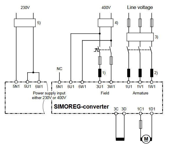
Wiring Details
Below image show terminal details:
Faults & Alarms
Search from below list for 6RA70 drive faults & alarms:
| Fault Codes | Cause & Solution |
|---|---|
| F001 Failure of electronics power supply | Cause: Failure of the electronics supply voltage (terminals 5U1, 5W1, 5N1) in “RUN” state for longer than the “restart” time set in parameter P086 or the electronics are operating on undervoltage. Possible fault causes: – Line contactor has opened in “RUN” state – Brief supply failure – Supply voltage too low Soultion: Fault value: r047 Index 002 to 016: 1 Electronics supply voltage in “RUN” has been interrupted for longer than setting in P086 i002 Duration of actual supply failure in 1/10 seconds 2 Supply failure prewarning responds periodically – 3 Supply failure prewarning is active for longer than 1.28 s |
| F004 Phase failure in armature supply | Cause: The supply voltage RMS value, calculated from the area of each supply half-wave (rectified average value * peak factor), must be greater than the response value for phase failure monitoring The distance between two identical supply zero passages of a phase must not exceed 450 degrees. If one of these two conditions remains unfulfilled for longer than the “restart time” set in P086, a fault message is activated. After switch-on, the converter waits in operating states o4 and o5 together for a period not exceeding the setting in P089 for voltage to appear at the power terminals (and for field current) before activating the fault message. Possible fault causes: – Parameter P353 is incorrectly set – Armature phase has failed – Line contactor opened in operation – Fuse has blown on three-phase side in armature circuit – Fuse has blown in power section – Interruption in a thyristor firing pulse cable (auxiliary cathodes at connectors X12, X14, X16 are voltage carriers). Soultion: Fault value: 1 Voltage failure has occurred in armature supply (1U1, 1V1, 1W1) (when P086=0) 2 Delay time set in parameter P089 has expired in operating state o4 3 Fuse has blown in power section 4 Voltage failure has lasted longer than period set in P086 (if this is >0) 6 The “Main contactor checkback” (control word 2 bit 31) [see also P691] did not switch to “1” before the time set in P095 ran out, or switched back to “0” during operation [V1.8 and later]. |
| F005 Fault in the field circuit | Cause: The line voltage RMS value calculated from the area of each network half-wave (rectification average value * peak factor) must be greater than the response value for phase failure monitoring The distance between two identical network zero passages of the voltage for the field converter must not exceed 450 degrees. The actual field current K0265 equals < 50% of the required field current setpoint K0268 for more than 500ms. This monitoring function is effective only if the field current setpoint corresponds to >2% of the converter rated field current. [In SW 1.9 and later, the percentage (50%) and time (500ms) can be altered in P396 and P397 respectively] If one of the fault conditions described persists in operation (or ≤ o4) for longer than the “restart” time set in P086, the fault message is output. After the converter is switched on, it waits in operating state o5 for a period not exceeding the setting in P089 for the field supply voltage or sufficiently high field current before this fault message is activated. Monitoring for timeout as the field decays or builds up after initiation of field reversal (fault values 6 and 7) is not implemented until SW 1.7 and later. Possible fault causes – Threshold for phase failure (P353) set incorrectly – Undervoltage / overvoltage threshold (P351, P352) set incorrectly – Field phase failed – Line contactor opened during operation – Fuse blown in the field circuit – Field current controller and/or field current precontrol not optimized or badly optimized (check P112, P253 to P256; possibly execute current controller optimization) – Check P396 (field current monitoring threshold) and P397 (field current monitoring time) – If the fault value is 6: Offset fault in the actual field current value sensing, relevant parameter: P825.i01-i03 (Offset depends on P076.i02) or P394, P395 (Threshold and hysteresis for message I_field < I_field_min) must be checked – If the fault value is 7: Circuit for the “new” field direction is interrupted (e.g. because the contactor for “new” field direction does not pick up), P398, P399 (Threshold and hysteresis for message I_field < I_field_x) must be checked Solution: Fault value: 1 Voltage failure occurred in the field supply (terminals 3U1 and 3W1) (if P086 = 0) 2 Delay time according to P089 elapsed in state o5.1. Wait until the voltage and frequency at the field power section are within the tolerance range (P351, P352, P353, P363, P364). 3 Delay time according to P089 elapsed in state o5.0 Wait until IField act (K0265) > 50% of the instantaneous field current setpoint K0268 [as of SW 1.9, can be altered by means of P396] and until “I Field extern > I f min” (see P265) 4 After P086 > 0 has elapsed (time for automatic restart) in operating state ≤ o4: Voltage failure in the field supply or IField act (K0265) < 50% IField set (K0268) for longer than 500 ms [as of SW 1.9, can be altered by means of P396 or P397] or "I Field extern > I f min” (see P265) 5 When P086 = 0 (no automatic restart) in operating state ≤ o4: IField act (K0265) < 50% IField set (K0268) for longer than 500 ms [as of SW 1.9, can be altered by means of P396 or P397] or “I Field extern > I f min” (see P265) 6 If field reduction before field reversal, I_field ≤ I_field_min (P394) is not reached within 30 s 7 If field build-up after field reversal, I_field > I_field_x (P398) is not reached within 30 s |
| F006 Undervoltage | Cause: The voltage across terminals 1U1, 1V1 or 1W1 and 3U1, 3W1 was lower than the response threshold for longer than the “restart time” set at P086 and the delay time according to P361 has expired.Possible fault causes – Line undervoltage – Monitoring values set too sensitively or incorrectly (P351, P078) Soultion: Fault value: r047 Index 002 to 016: 1. Undervoltage has occurred (when P086=0) i002 Number of phase that has activated fault message – 0 … Phase UV – 1 … Phase VW – 2 … Phase WU – 3 … Phase field – i003 Incorrect voltage value (normalized to 16384) 2. Undervoltage persists for longer than time set in parameter P086 (if this is set to >0) |
| F007 Overvoltage | Cause: The voltage across terminals 1U1, 1V1 or 1W1 and 3U1, 3W1 was higher than the response threshold for longer than the “restart time” set at P086 and the delay time according to P362 has expired.Possible fault causes – Line overvoltage – Monitoring values set too sensitively or incorrectly (P352, P078) NOTICE: This monitoring function is deactivated in the delivery state. It can be activated via parameter P820. Soultion: Fault value: r047 Index 002 to 016: 1. Overvoltage has occurred 002 Number of phase that has activated fault message – 0 … Phase UV – 1 … Phase VW – 2 … Phase WU – 3 … Phase field – i003 Incorrect voltage value (normalized to 16384) 2. Undervoltage persists for longer than time set in parameter P086 (if this is >0) |
| F008 Line frequency less than the minimum line frequency acc. to parameter P363 | Cause: This fault message is activated if the line frequency is less than the minimum line frequency (for longer than the “restart time” set in parameter P086) Soultion: Fault value: 1 Frequency of the armature supply < minimum line frequency 2 Frequency of the field supply < minimum line frequency 4 Line frequency less than the minimum line frequency for longer than set in parameter P086 (if >0) |
| F009 Line frequency greater than the maximum line frequency acc. to parameter P364 | Cause: This fault message is activated if the line frequency is greater than the maximum line frequency (for longer than the “restart time” set in parameter P086). Note: Up to software version 1.7 the threshold for activation of the fault message (maximum line frequency) is 65Hz Soultion: Fault value: 1 Frequency of the armature supply > maximum line frequency 2 Frequency of the field supply > maximum line frequency 4 Line frequency greater than the maximum line frequency for longer than set in parameter P086 (if >0) |
| F011 Telegram failure at GSST1 | Cause: when P780 = 2: USS telegram failure at G-SST1 (active from the first receipt of a valid protocol in all operating states) After the receipt of the first valid protocol, no further telegrams have been received within the time period set in parameter P787. Possible fault causes – Cable break – Error in USS master |
| F012 Telegram failure at GSST2 | Cause: when P790 = 2: USS telegram failure at G-SST2 (active from the first receipt of a valid protocol in all operating states) After the receipt of the first valid protocol, no further telegrams have been received within the time period set in parameter P797. Possible fault causes – Cable break – Error in USS master when P790 = 4 or 5: Peer-to-peer telegram failure at G-SST2 (active in operating states of ≤ o6) After the receipt of the first valid protocol, no further telegrams have been received within the time period set in parameter P797. Possible fault causes – Interruption in connecting cable – EMC interference on connecting cable – P797 is set too low |
| F013 Telegram failure at GSST3 | 1. when P800 = 2: USS telegram failure to G-SST3 (active from the first receipt of a valid protocol in all operating states) After the receipt of the first valid protocol, no further telegrams have been received within the time period set in parameter P807. Possible fault causes – Cable break – Error in USS master 2. when P800 = 4 or 5: Peer-to-peer telegram failure at G-SST3 (active in operating states of ≤ o6) After the receipt of the first valid protocol, no further telegrams have been received within the time period set in parameter P807. Possible fault causes – Interruption in connecting cable – EMC interference on connecting cable – P807 is set too low |
| F014 Telegram failure at paralleling interface | (active when U800 = 1 or 2 from the first receipt of a valid protocol in all operating states) After the receipt of the first valid protocol, no further telegrams have been received within the time period set in parameter U807. Possible fault causes – Interruption in connecting cable – EMC interference on connecting cable – U807 is set too low |
| F015 Telegram failure on one SIMOLINK board | (active when U741 > 0 as soon as the first valid telegram is received) After receipt of one valid telegram, no further valid telegrams have arrived within the period set in parameter U741. Possible fault causes – Break in connecting cable – Parameter setting change during telegram exchange (for parameters see Section 11 “Configuration of SIMOLINK board) – U741 is set to low Fault value: 1 Telegram failure on 1 st SLB 2 Reserved |
| F016 Hardware fault on expansion board EB1 | Fault value: 1 Fault on first EB1 2 Fault on second EB1 |
| F017 Hardware fault on expansion board EB2 | Fault value: 1 Fault on first EB2 2 Fault on second EB2 |
| F018 Short circuit or overloading of binary outputs | Possible fault causes: – Short circuit or overload at terminals 46, 48, 50 or 52 and 26 or 34 Fault value: r047 Index 002 to 016: 1. Short circuit or overload at binary outputs i002 Bit 8 = 1: Overload at terminal 46 – Bit 9 = 1: Overload at terminal 48 – Bit 10 = 1: Overload at terminal 50 – Bit 11 = 1: Overload at terminal 52 – Bit 12 = 1: Overload at terminal 26 (15 V output) – Bit 13 = 1: Overload at terminal 34, 44 and/or 210 (24 V output) NOTICE: This monitoring function is deactivated in the delivery state. It can be activated via parameter P820 |
| F019 Fault message from free function block FB286 | Fault Value: – 1 the binector wired via parameter U100 Index.005 is in the state log.”1” – 2 the binector wired via parameter U100 Index.006 is in the state log.”1” – 3 the binector wired via parameter U100 Index.007 is in the state log.”1” – 4 the binector wired via parameter U100 Index.008 is in the state log.”1” |
| F020 Fault message from free function block FB287 | Fault value: – 1 the binector wired via parameter U101 Index.005 is in the state log.”1” – 2 the binector wired via parameter U101 Index.006 is in the state log.”1” – 3 the binector wired via parameter U101 Index.007 is in the state log.”1” – 4 the binector wired via parameter U101 Index.008 is in the state log.”1” |
| F021 External fault 1 | Cause: Bit 15 in control word 1 was in the log. “0” state for longer than the time set in P360 index 001 |
| F022 External fault 2 | Cause: Bit 26 in control word 2 was in the log. “0” state for longer than the time set in P360 index 002. |
| F023 Fault message from free function block FB2 | Fault value: – 1 the binector wired via parameter U100 Index.001 is in the state log.”1” – 2 the binector wired via parameter U100 Index.002 is in the state log.”1” – 3 the binector wired via parameter U100 Index.003 is in the state log.”1” – 4 the binector wired via parameter U100 Index.004 is in the state log.”1” |
| F024 Fault message from free function block FB3 | Fault value: – 1 the binector wired via parameter U101 Index.001 is in the state log.”1” – 2 the binector wired via parameter U101 Index.002 is in the state log.”1” – 3 the binector wired via parameter U101 Index.003 is in the state log.”1” – 4 the binector wired via parameter U101 Index.004 is in the state log.”1” |
| F025 Brush length too short | When parameter P495=2 (binary sensing of brush length), fault message at log.”0” signal (longer than 10s) at terminal 211 Possible fault causes – Encoder for brush length has responded – Open circuit in encoder cable |
| F026 Bearings in bad condition | When parameter P496=2 (bearing condition sensing) fault message at log. “1” signal (longer than 2 s) at terminal 212 Possible fault causes – Encoder for bearing condition has responded |
| F027 Air-flow monitoring of motor fan | When parameter P497=2 (air-flow monitoring), fault message at log ”0” signal (longer than 40s) at terminal 213 Possible fault causes – Encoder for fan monitoring has responded – Open circuit in encoder cable |
| F028 Motor overtemperature | When parameter P498=2 (thermostat connected), fault message at log. “0” signal (longer than 10s) at terminal 214 Possible fault causes – Thermostat for monitoring motor temperature has responded – Open circuit in encoder cable |
| F029 Motor overtemperature | 1. Select via P493=2 or 3 (temperature sensor at terminals 22 / 23) or P494=2 or 3 (temperature sensor at terminals 204 / 205) 2. When parameter P490.01=1 (KTY84 at terminals 22 / 23) or P490.02=1 (KTY84 at terminals 204 / 205): – The fault message is activated if the motor temperature reaches or exceeds the value set in parameter P492. 3. When parameter P490.01=2, 3, 4 or 5 (PTC thermistor at terminals 22 / 23) or P490.02=2, 3, 4 or 5 (PTC thermistor at terminals 204/ 205): – The fault message is activated if the motor temperature reaches or exceeds the response value of the selected PTC thermistor. Fault value: 1 Fault activation through temperature sensor at terminals 22 / 23 2 Fault activation through temperature sensor at terminals 204 / 205 |
| F030 Commutation failure or overcurrent has occurred or test command has been issued via U583 | Possible error causes – Mains voltage dip in regenerative feedback mode – Current control loop not optimized Fault value: r047 Index 002 to 016: 1 The blocking voltage time area for the commutating thyristor pair was too small – for i001= 1 to 3 and 5, i002 to i006 are valid – for i001= 4, i002 to i015 is invalid 2 The current crest curve breaks upwards – for i001= 1 to 3 and 5, i002 to i006 are valid – for i001= 4, i002 to i015 is invalid 3 The maximum current value was higher than 250% of the actual rated device current according to r072i002 – i002 Delay angle (K0100) in case of error – i003 Actual EMF (K0287) in case of error – i004 Trigger circuitry diagnostics (K0989) in case of error – i005 Actual field current (K0265) in case of error – i006 Number of pulses (K0105) in case of error 4 A paralleled SIMOREG DC-MASTER has detected a commutation failure or overcurrent 5 test command has been issued via U583 |
| F031 Speed controller monitoring | Cause: The monitor responds when the difference between the connectors selected in P590 and P591 (factory setting: Setpoint/actual value difference of speed controller) exceeds the limit set in parameter P388 for longer than the time set in parameter P390. Possible fault causes – Open control loop – Controller not optimized – P590 or P591 is not correctly parameterized |
| F032 SIMOREG CCP not ready | Possible error causes – No connection or cable break at X172 (G-SST2) – No connection or cable break at X165 (paralleling interface master) in a parallel connection – No connection or cable break at X29_PAR or X30_PAR (extinction-pulse interface) in a parallel connection – Hardware defective in charging circuit of extinguishing capacitors – Blown fuse in the line-side or motor-side armature circuit – Blown fuse in the precharging circuit for the chopper capacitors – Required cooling phase for chopper resistors still in progress – MLFB (order number) data of the SIMOREG CCP (n570, n571, n572) are invalid or nonexistent Fault value: r047 Index 002 to 016: 1 No voltage at U, V, W terminals of SIMOREG CCP 2 Voltage at C-D on CCP does not match voltage at C-D on SIMOREG DC-MASTER 3 Surge absorbing capacitors of SIMOREG CCP have not reached setpoint voltage 4 Paralleling interface cable is not connected to SIMOREG CCP assigned to paralleling master 5 No connection between SIMOREG DC-MASTER and SIMOREG CCP via G-SST2 serial interface (r799.i001 is not incremented) 6 No connection between parallel SIMOREG CCPs 7 Contents of technical data memory on SIMOREG CCP (MLFB, rated values, serial number) invalid 11 I2t value (n575) of voltage chopper 1 is too high (> 100%) 12 I2t value (n576) of voltage chopper 2 is too high (> 50%) 20 Chopper capacitors not completely precharged in time set with P089 or the condition in accordance with fault value 5 is satisfied – for i001= 1 to 12, i002 to i006 are valid – for i001= 20, only i002 is valid – i002 SIMOREG CCP status (K0574) in case of error – i003 I2t value of chopper 1 (K0575) in case of error – i004 I2t value of chopper 2 (K0576) in case of error – i005 Actual armature voltage (r038) in case of error in 0.1 V for i005 > 32767: U ARMATURE [V] = (65536-r047i005)/10 – i006 effective time until the fault initiation in 20 ms |
| F033 Fault message from free function block FB4 | Fault Value: 1 the binector wired via parameter U102 Index.001 is in the state log.”1” 2 the binector wired via parameter U102 Index.002 is in the state log.”1” 3 the binector wired via parameter U102 Index.003 is in the state log.”1” 4 the binector wired via parameter U102 Index.004 is in the state log.”1” |
| F034 Fault message from free function block FB5 | Fault value: 1 the binector wired via parameter U103 Index.001 is in the state log.”1” 2 the binector wired via parameter U103 Index.002 is in the state log.”1” 3 the binector wired via parameter U103 Index.003 is in the state log.”1” 4 the binector wired via parameter U103 Index.004 is in the state log.”1” |
| F035 Drive is blocked | This monitoring function responds if the following conditions are fulfilled for longer than the period set in parameter P355: – Positive or negative torque or armature current limit – The armature current is higher than 1% of the converter rated armature DC current – The actual speed is less than 0.4% of maximum speed Possible fault causes – Drive is blocked |
| F036 No armature current is flowing | This monitoring function responds if the armature firing angle is at the rectifier stability limit for more than 500 ms and the armature current is less than 1% of the converter rated armature DC current. Possible fault causes – Armature circuit is open (e.g. DC fuses have blown, open circuit, etc.) – Rectifier stability limit αG (P150) is incorrectly set – Drive is operating at αG limit (e.g. due to supply undervoltage) – EMF is too high because maximum speed setting is too high, refer to P083, P115, P143, P741) – EMF is too high because field weakening is not selected (refer to P082) – EMF is too high because field current is set too high (refer to P102) – EMF is too high because transition speed for field weakening is set too high (refer to P101) ?? |
| F037 I2t motor monitor has responded | This monitoring function responds when an I2t value is reached which corresponds to the final temperature at 110% of the rated motor armature current. Possible fault causes – Parameter P114 is incorrectly set – Drive has been operating for too long at >110% of rated motor armature current |
| F038 Overspeed | This fault message is activated if the actual speed value (selected in P595) exceeds the positive (P380) or negative (P381) threshold by 0.5%. Possible fault causes – Lower current limit has been input – Current-controlled operation – P512, P513 are set too low – Tachometer cable contact fault in operation close to maximum speed |
| F039 I2t power section monitor has responded | This monitoring function responds if the calculated I2t value of the power section reaches the permissible value for the power section concerned (see also P075). Possible fault causes – Drive has been operating at overload for too long – Parameter P075 is incorrectly set – Parameter P077 is incorrectly set |
| F040 Electronics supply disconnected in active fault status | This fault message is activated if the electronics power supply has been disconnected, even though a fault was displayed and not yet acknowledged. Possible fault causes – Not all fault messages have been acknowledged |
| F041 Ambiguous selection of parameter set or ramp-function generator | While an optimization run is in progress, the function data set selection must not be changed. Fault F041 is displayed if another, different function data set is selected while an optimization run is being executed. – Check whether ramp-function generator parameter set 1 or 2 or 3 (parameters P303 to P314) is clearly selected. If parameter sets 2 and 3 are selected simultaneously for more than 0.5s, then fault message F041 is displayed. While the parameter set selection is ambiguous, the system continues to apply the last clearly identified ramp-function generator parameters. Possible fault causes – P676 or P677 (selection of binectors which determine the active function data set in control word 2, bits 16 and 17) is incorrectly set – P637 or P638 (selection of binectors which determine ramp-function generator setting) is incorrectly set Fault value: 2 The selection of the function data set has been changed during an optimization run 3 Ambiguous selection of ramp-function generator parameter set |
| F042 Tachometer fault | Possible fault causes – Open circuit in tachometer or pulse encoder cable. – Tachometer of pulse encoder cable incorrectly connected. – Pulse encoder supply has failed. – Polarity for actual speed value (P743) is incorrectly set. – Armature circuit data (P110 und P111) are incorrectly set (execute current controller optimization run). – Tachometer or pulse encoder defective – Pulse encoder supply voltage is incorrectly set (P140) – The field polarity is not reversed by the external hardware when the field is reversed. Fault value: r047 Index 002 to 016: – 1 Open circuit in tachometer or pulse encoder cable: i002 Actual speed value (K0179) in case of fault – 2 Polarity of tachometer or pulse encoder is incorrect: i003 Actual EMF value (K0287) in case of fault |
| F043 EMF too high for braking operation | This fault message is activated if the following 5 conditions are fulfilled when a torque direction reversal is requested (selection of MI or MII): – P272=0 (fault message is parameterized and not alarm + field weakening) – A parameterized, additional, torque-free interval (P160 ≠ 0) has expired – Parallel drive is ready for engagement of the new torque direction – The absolute value of the armature current (K0118, filtered with P190) requested in the new torque direction is >1% of P072.002 – The calculated firing angle (K0101) for the armature current requested for the new torque direction is >165 degrees or >P151 when P192=1 Possible fault causes: – No “speed-dependent field weakening” (P081=0) is parameterized even though operation in the field weakening range is needed for the requested maximum speed Note: In motor operation, it is possible to reach EMF values corresponding to the peak of the phase-to-phase supply voltage at a firing angle of αG=30° (rectifier stability limit P150) and low armature currents. – Setpoint EMF for field weakening operation too high (parameter P101 is set too high) – Supply voltage dip – EMF controller or field current controller is not optimized, possibly resulting in excessive EMF on power-up. Fault value: r047 Index 002 to 016: 1. Calculated firing angle (armature) before limitation (K0101) – i002 Instantaneously measured actual EMF (K0287) – i003 Armature current controller setpoint (K0118) |
| F044 A slave connected to the paralleling interface is not operating | active when U800 = 1 or 2 and U806>10 (master) after receipt of the first valid protocol in operating states – –, I, II Fault value: r047 Index 002 to 006: 1 A fault message is active on a slave 2 A slave is not in operation (e.g. because its enable input is set to “0”) – i00x = Status word 1 from slave x |
| F046 Analog select input for main setpoint (terminals 4 and 5) faulty | This fault message is activated when P700=2 (current input 4 to 20 mA) and an input current of less than 2mA is flowing. Possible fault causes – Open circuit in supply cable – P700 is incorrectly set |
| F047 Analog select input 1 (terminals 6 and 7) is faulty | This fault message is activated when P710=2 (current input 4 to 20 mA) and an input current of less than 2mA is flowing. Possible fault causes – Open circuit in supply cable – P710 is incorrectly set |
| F048 Fault in measuring channel for digital speed sensing using pulse encoder | 1. Disturbances on encoder cables: Faults on the encoder cables (transitions to 0 with a 1 signal or to 1 with a 0 signal) are signalled as a rotational direction change by the evaluation circuit. Frequent changes in rotational direction can occur only at speeds around 0. The fault message is activated if 10 consecutive pulse encoder signal evaluations identify “direction of rotation change” at a speed of ≥ 48 rev/min and an EMF > threshold (see below). 2. Pulse encoder defective: The fault message is activated if, at an EMF > threshold (see below) 10 consecutive pulse encoder signal evaluations identify “implausible characteristics” of these signals (i.e. frequent rotational direction changes, edges too close together, failure of an encoder cable or short circuit between two encoder cables). Possible fault causes – EMC-related interference on a pulse encoder signal (terminals 28 to 31) – Interruption in an encoder cable – Short circuit between an encoder cable and the supply voltage or another encoder cable – P110 or P111 is incorrectly set (resulting in incorrectly calculation of EMF) Note: When the speed encoder is operating correctly, signal sequences, which are characteristic of a faulty pulse encoder or disturbances on the pulse encoder cables, may occur continuously at the input terminals (e.g. continuous changes in rotational direction or short pulse intervals) at about 0 speed, e.g. as the result of slight oscillation around a bright/dark transition on the speed encoder disk). Fault value: 1 Disturbances on encoder cables 2 Defective pulse encoder |
| F050 Optimization run not possible | Cause: A fault has occurred during an optimization run. NOTE: The contents of r047, Index 002 to 016, can provide specialists with more detailed information about fault causes. For this reason, please read out and document all the indices associated with this fault. Fault value: 1 Armature current is too low when α=30° and EMF=0. (average armature current <75% of IA, motor or <75% of IA, rated) Possible cause: – Armature circuit interrupted – High-resistance load – P150 (Alpha G limit) has been set to excessively high value 2 It was not possible to determine the armature circuit resistance (P110) because the armature current was ≥ 37.5 % of P100 in fewer than 20 of the 150 firing cycles of the measuring phase. Possible cause: -Armature current of 37.5% of P100 (I A, motor) is no longer possible (although a current of 75% of P100 was already flowing, maybe a fuse has blown). 3 Armature current peaks are too small at α=30° and EMF=0 (armature current peak value <50% of IA, motor or <50% of IA,rated) Possible cause: • Armature circuit inductance is too high (field supply from armature terminals) • P150 (Alpha G limit) has been set to excessively high value Possible remedy: • Reduce P100 (IA,motor) while this optimization run is in progress 4 The armature circuit inductance (P111) cannot be determined from the sampled values of the armature current and line voltage of the armature current crest last generated Possible cause: •P100 (IA,motor) or r072.i002 (IA,rated) very much smaller than actual motor rated current of the armature •LA >327.67mH (armature circuit inductance too large) •P100 (IA,motor) very much smaller than r072.i002 (IA,rated) •Armature circuit short-circuited 5 Offset adjustment of actual field current sensing is not possible (value detected for P825 is outside permissible value range) Possible cause: • Fault in actual field current sensing circuit (defective A7004 gating board or A7001 electronics board) 7 The field circuit resistance (P112) is indeterminable (the actual field current does not reach the internally specified setpoint of 95% of P102 as a result of P112 variation) Possible cause: • RA >3276.7Ω • Fault in actual field current sensing circuit (defective gating board or A7001 electronics board) • The command “Inject standstill field” is applied • P102 is set too high • A thyristor in the field bridge is not firing 8 80% of rated EMF (K287=P101 – P100 * P110) cannot be reached within 15s (or maximum of the three set acceleration times) Possible cause: • Acceleration time (P303, P307, P311) is set too low • P101 does not match the set maximum speed (UA at nmax < P101) or setting for P102 is too low • The command “Ramp-function generator enable”=0 or ”Ramp-function generator stop”=1 9 Field current control loop is not stable enough to record field characteristics (30s after injection of internal field current setpoint, actual field current is deviating by more than (0.39% of P102 + 0.15 % of r073.002) from the setpoint) Possible cause: • Field current controller or field current precontrol is not optimized or optimized badly (check P112, P253 to P256 or execute a current controller optimization run (P051=25)) 10 Field characteristic is not uniform (i.e. in spite of field current setpoint reduction, the flux values of this measuring point calculated from EMF and actual speed are rising) Possible cause: • High armature reaction and sharp load variations during recording of field characteristics • Field current controller or field current precontrol is not optimized or optimized badly (check P112, P253 to P256 or execute a current controller optimization run (P051=25)) 11 A lower field current limit of ≥ 50% of P102 (IF,motor) is applied (for this reason, it is not possible to plot a minimum of 9 field weakening measuring points) Possible cause: • P103 ≥ 50% of P102 Check P614 ! 12 The drive has reached the positive torque limit even though the applied field current setpoint is still ≥ 50% of P102 (IF,motor) Possible cause: • Armature current is very “unsteady”, e.g. due to high speed controller P gain setting in P225 (on drive with high integral- action time). In this case, setting a lower actual speed filtering value in P200 and execution of another speed controller optimization run (P051=26) may help. • Check torque limits 13 The drive has reached the positive armature current limit even through the applied field current setpoint is still ≥ 50% of P102 (IF,motor) Possible cause: • Armature current is very “unsteady”, e.g. due to high speed controller P gain setting in P225 (on drive with high integral- action time). In this case, setting a lower actual speed filtering value in P200 and execution of another speed controller optimization run (P051=26) may help • Check armature current limits 14 The speed has changed by more than 12.5% at a constant speed setpoint even through the applied field current setpoint is still ≥ 50% of P102 (IF,motor) Possible cause: as for fault value 12 15 The EMF setpoint is too small to plot a field characteristic EMFset = UA – IA,motor * RA = P101 – P100 * P110 < 10% of 1.35 * P078.i001 (e.g. P078.i001 = 400 V . . . minimum EMFset = 54 V) 16 Field weakening operation is not allowed in operation without a tachometer (P083=3) 17 The field current controller cannot be optimized because the field circuit time constant cannot be determined (actual field current does not decay after switch-off to below 0.95*initial value within approximately 1s or to below 0.8 * 0.95*initial values within approximately 2 s) Possible cause: • Setting in P103 is too high • Field circuit inductance is too high • Fault in actual field current sensing circuit (gating board or A7001 electronics board defective) • Ratio r073.02 / P102 is too high (change P076.02 if necessary) 18 Field weakening range is too wide, i.e. during power-up (at full field) to a speed setpoint of +10% nmax , the |EMK| is > 77% of setpoint EMF (P101 – P100 * P110) Possible cause: • Maximum speed setting is incorrect • Pulse encoder parameters are incorrect (P140 to P143) • Parameters for tachometer adaptation are incorrect (P741) • Setpoint EMF is not correct (P101, P100, P110) • An excessively high load torque (in positive or negative direction, e.g. a suspended load) causes the drive to rotate, one of the armature current or torque limits may be parameterized too low 19 A steady-state actual speed of +10%, +20%, +30% . . . or +100% of the maximum speed cannot be reached within 3 minutes (or maximum value of the three set acceleration times) in speed-controlled operation (the speed setpoint/actual value difference averaged over 90 firing cycles must equal <0.1% nmax for a specific time period) Possible cause: • Acceleration time is set too low (P303, P307, P311) • Drive is blocked • An excessively high load torque (in positive or negative direction, e.g. a suspended load) causes the drive to rotate, one of the armature current or torque limits may be parameterized too low • Poor speed controller setting (P225, P226, P228) or speed controller is parameterized as pure P controller or with droop • A band elimination filter (P201, P202 or P203, P204) is active • Command “Ramp-function generator enable” =0 or ”Ramp-function generator STOP” =1 is applied • “Field weakening operation” (P081 = 1) is not parameterized 20 Current limit is too low (With speed controller optimization run: Less than 30% or 45% of P100 (IA,motor) + the armature current required for zero speed, With optimization run for friction moment and moment of inertia compensation: Less than 20% of P100 (IA, motor) + the armature current required for a steady-state speed corresponding to 10% of maximum speed) 21 Field weakening range is too wide (nact < +7% nmax produces |EMF| > 54% setpoint EMF) (setpoint EMF= K289= P101 – P100 * P110) Possible cause: • Maximum speed setting is incorrect • Pulse encoder parameters are incorrect (P140 to P143) • Parameters for tachometer adaptation are incorrect (P741) • Setpoint EMF is not correct (P101, P100, P110) • Caution: Even a high absolute negative actual speed value can produce an | EMF | of > 54% setpoint EMF 22 With speed controller optimization run: With an acceleration current equaling 20% or 30% of P100 (IA, motor) + armature current required for zero speed or With optimization run for friction moment and moment of inertia compensation: With an acceleration current equaling the current required to achieve a steady-state speed of 10% of maximum speed + 20% of P100 (IA, motor), the maximum speed cannot be reached within 45s +7% Possible cause: • Centrifugal mass is too large • Drive is blocked, heavily speed-dependent or excessively high load torque • “Active” load is attempting to maintain a certain speed Possible remedy: • Increase P100 while the optimization run is in progress in order to raise the applied acceleration current during optimization (during the speed controller optimization run, a maximum of 45% of IA, motor (+ armature current for zero speed) is applied as the armature current setpoint, IA,motor (P100) can thus be increased to 2.2 times the value at maximum without exceeding 100% IA, motor during optimization) 23 With speed controller optimization run: With an acceleration current equaling 20% or 30% of P100 (IA, motor) + armature current required for zero speed or With optimization run for friction moment and moment of inertia compensation: With an acceleration current equalling the current required to achieve a steady-state speed of 10% of maximum speed + 20% of P100 (IA, motor), the maximum speed or 100% of setpoint EMF cannot be reached within 90s +13% Possible cause: • Flywheel mass is too large • Drive is blocked, heavily speed-dependent or excessively high load torque • “Active” load is attempting to maintain a certain speed Possible remedy: • Increase P100 while the optimization run is in progress in order to raise the applied acceleration current during optimization (during the speed controller optimization run, a maximum of 45% of IA, motor (+ armature current for zero speed) is applied as the armature current setpoint, IA,motor (P100) can thus be increased to 2.2 times the value at maximum without exceeding 100% IA, motor during optimization) 24 With speed controller optimization run: The actual speed does not drop to below +2% of maximum speed or to below the speed threshold nmin set in P370 within 2 minutes With optimization run for field weakening: The actual speed does not drop to below +2% of maximum speed or to below the speed threshold nmin set in P370 within 10 minutes With optimization run for friction moment and moment of inertia compensation: The actual speed does not drop to below +2% of maximum speed or to below the speed threshold nmin set in P370 within 11 or 2 minutes Possible cause: • Single-quadrant drive coasts to a standstill too slowly 25 The average armature current required for the speed range from +7% to approximately +13% of maximum speed to cover the friction and/or steady-state load torque cannot be calculated Possible cause: • Drive with very little friction or very small integral-action time and, as a result of the very short measuring time, computational inaccuracies during evaluation • Distorted or disturbed actual speed value • Large flywheel mass that is coupled to the drive via long shaft with high torsion, possibly via a coupling with large amount of play Possible remedy: • Reduce P100 for duration of the optimization run to decrease the acceleration current applied during optimization and thus to lengthen the measuring time 26 Load torque too high (nset =0% nmax results in nict ≥ 40% nmax) (actual speed value is averaged over 90 firing cycles, speed monitoring at ≥ 40% nmax does not start for 1s after application of speed setpoint of nset=0) Possible cause: • An excessively high load torque (in a positive or negative direction, e.g. suspended load) causes the drive to rotate (the speed controller parameters are parameterized according to the factory setting during this run) • One of the armature current or torque limits is parameterized too low (the motor field may not be reaching full field strength fast enough with the result that the initial motor torque is too low) • Maximum speed setting is incorrect • Pulse encoder parameters are incorrect (P140 to P143) • Parameters for tachometer adjustment are not correct (P741) 27 Load torque is too high (nset=0% nmax results in |EMF| >100% setpoint EMF) (EMF monitoring at ≥ (P101 – P100 * P110) does not start for 1 s after application of speed setpoint of nset=0) Possible cause: • An excessively high load torque (in a positive or negative direction, e.g. suspended load) causes the drive to rotate (the speed controller parameters are parameterized according to the factory setting during this run) • One of the armature current or torque limits is parameterized too low (the motor field may not be reaching full field strength fast enough with the result that the initial motor torque is too low) • Maximum speed setting is incorrect • Pulse encoder parameters are incorrect (P140 to P143) • Parameters for tachometer adjustment are not correct (P741) • Setpoint EMF settings are incorrect (P101, P100, P110) 28 A steady-state actual speed corresponding to 0% of maximum speed cannot be reached within 0 s in speed-controlled operation (the speed setpoint/actual value difference averaged over 90 firing cycles must be <1.0% nmax for a total of 4s) Possible cause: As for fault value 26 29 The calculated armature circuit inductance is greater than 327.67 mH, therefore P111 = 327,67 mH has been set. All other parameters (the current controller parameters P155 and P156 too) have been set correctly despite that. (For the real armature circuit inductance in mH, see r047.i010). Possible cause: •e.g. field supply from the armature terminals 30 The calculated armature circuit inductance is greater than 327.67 mH and the calculated armature circuit resistance is greater than 32.767 Ω, therefore P111 = 327,67 mH and P110 = 32,767 Ω has been set. All other parameters have also been set. However, the values of the current controller parameters P155 and P156 might differ from the optimum setting. Possible cause: •e.g. field supply from the armature terminals 31 The calculated armature circuit resistance is greater than 32.767 Ω, therefore P110 = 32,767 Ω has been set. All other parameters have also been set. Possibly the calculated P111 and therefore also the current controller parameters P155 and P156 have been distorted by the limitation in P110 . Possible cause: •e.g. field supply from the armature terminals 50 The protocol selection for basic-device interface G-SST2 has not been set to communication with the SIMOREG CCP. Possible remedy: Set P790 to 6 51 The protocol counter of the error-free telegrams r799.i001 is not incremented. Communication with the SIMOREG CCP does not take place. Possible cause: e.g. defective cabling for the peer-to-peer connection at X172 52 Incorrect MLFB identification number of the SIMOREG CCP (n570 < 250, see r047.i003) Please contact your nearest SIEMENS agent 53 The electric strength of the SIMOREG CCP is too low. The SIMOREG device’s rated input voltage set in P078.i001 (see r047.i003 in V) is higher than the rated supply voltage of the SIMOREG CCP (see r047.i004 in V). It is not permissible to operate the SIMOREG CCP in this hardware configuration. 54 It is not possible to set parameter U578. The calculated voltage setpoint for precharging the surge absorbing capacitors in the SIMOREG CCP (see r047.i003 in V) is higher than the rectifier average of supply voltage actually being applied (minimum value in line with the lower tolerance limit in accordance with P351(see r047.i004 in V) See also the description for parameter U578 in the SIMOREG CCP operating instructions 55 The maximum energy – to be reduced during extinguishing – in the armature circuit (see r047.i003 in kJ) is higher than the energy that can be absorbed in the chopper resistors of the SIMOREG CCP (see r047.i003 in kJ). The selected SIMOREAG CCP is not suitable for the existing hardware configuration. See also step 5 in the section entitled “Commissioning steps” of the operating instructions of the SIMOREG CCP. 56 The value set at parameter P111 for the armature inductance is 0 Possible cause: The optimization run for the current controller has not been carried out. 57 In the existing software of the SIMOREG device, there are still no setting data for operation with SIMOREG CCP. Possible remedy: Update the SIMOREG software r047 Index 002: 1 Fault has occurred during optimization run for current controller and precontrol for armature and field (selected by means of P051=25) 2 Fault has occurred during optimization run for speed controller (selected through setting P051=26) 3 Fault has occurred during optimization run for field weakening (selected through setting P051=27) 4 Fault has occurred during internal offset adjustments (selected through P051=22) 5 Fault has occurred in optimization run for friction and moment of inertia compensation (selected through setting P051=28) 7 Fault has occurred during automatic setting of the parameters for SIMOREG CCP (was selected by means of P051=30) |
| F051 No optimization run when permanent memory is disabled | If P051.001 is set to 0 (write access to permanent memory disabled), it is not possible to execute an optimization run. |
| F052 Optimization run aborted as a result of external cause | This fault message is activated when the converter ceases operating in the RUN state (state I, II or –) during an optimization run (and thus in response to every FAULT) or if the EMERGENCY STOP or SHUTDOWN command is applied. The optimization run is aborted. Only those parameters which had been fully optimized prior to activation of the fault message are altered. When the STANDSTILL command is applied, this fault message is not activated if the optimization run for field weakening is interrupted after the 1st field weakening measuring point has been recorded or, in the case of the optimization run for friction and moment of inertia compensation, after the measuring point at 10% maximum speed has been determined. In these cases, the run may be interrupted by STANDSTILL so as to be able to complete the run in several stages (by repeated restarts) for a limited travel path. Fault value: r047 Index 002 to 016: 1. Run was aborted because converter is no longer operating in RUN mode (For example, this can occur when r047i002=2 in the case of a motor with a very high field circuit time constant → For help, see P051 = 26 in chapter 7.5) 2. Run was aborted because EMERGENCY STOP command was applied (speed controller setpoint =0) 3. Run was aborted because STANDSTILL command was applied (ramp-function generator setpoint=0) 4. Operation has been aborted because P051 was changed during the optimization run 5. Run was aborted because SWITCH-ON command was not applied within 30 s of selection of optimization run 6. Operation has been aborted because the OPERATING ENABLE command was not entered within 1 minute of selection of the optimization run. 7. Operation has been aborted because converter was not in operating state < o7.2 15 s after selection of the optimization run with P051 = 25, 26, 27 or 28 (input of OFF1 command may have been forgotten) – i002=1 Fault has occurred during optimization run for current controller and precontrol for armature and field (selected by means of P051=25) – i002=2 Fault has occurred during optimization run for speed controller (selected through setting P051=26) – i002=3 Fault has occurred during optimization run for field weakening (selected through setting P051=27) – i002=5 Fault has occurred in optimization run for friction and moment of inertia compensation (selected through setting P051=28) – i005 Operational state (K0800) in the event of a fault |
| F053 Fault message from free function block FB288 | Fault value: 1 the binector wired via parameter U102 Index.005 is in the state log.”1” 2 the binector wired via parameter U102 Index.006 is in the state log.”1” 3 the binector wired via parameter U102 Index.007 is in the state log.”1” 4 the binector wired via parameter U102 Index.008 is in the state log.”1” |
| F054 Fault message from free function block FB289 | Fault value: 1 the binector wired via parameter U103 Index.005 is in the state log.”1” 2 the binector wired via parameter U103 Index.006 is in the state log.”1” 3 the binector wired via parameter U103 Index.007 is in the state log.”1” 4 the binector wired via parameter U103 Index.008 is in the state log.”1” |
| F055 No field characteristic recorded | Possible fault causes – The optimization run for field weakening (P051=27) has not yet been executed. Fault value: 1 P170 = 1 (”torque control”) selected, but “no valid field characteristic has been recorded” (P117=0) yet 2 P081 = 1 (”speed-dependent field weakening”) selected, but “no valid field characteristic has been recorded” (P117=0) yet (P117=0) |
| F056 Important parameter is not set | This fault message is activated if certain parameters are still set to 0. Fault value: 1 Speed controller actual value selection in P083 is still set to 0 2 Rated motor armature current in P100 is still set to 0.0 3 Rated motor field current in P102 is still set to 0.00 (fault message only when P082 ≠ 0) 4 Rated DC current of external field device is still set to 0.00 in U838 (error message if P082 >= 21 only) |
| F058 Parameter settings are not consistent | Inconsistent values have been set in mutually dependent parameters. Fault value: 2 The parameters for speed-dependent current limitation are not set correctly (the following applies: P105>P107 (I1>I2) and P104 < P106 (n1 4 The first threshold for P gain adaptation of the speed controller set in parameter P556 is higher than the second threshold setting in parameter P559 4 P557 is set to greater than P560 5 P558 is set to greater than P561 7 If P083=1 (analog tachometer), then P746 may not equal 0 (main actual value is not connected) 8 If P083=2 (pulse encoder), then P140 may not equal x0 (no pulse encoder installed) 9 If P083=3 (EMF control) then P082 may not equal x1x (field weakening operation) 10 P090 (stabilization time for supply voltage) >P086 (time for automatic restart) 11 P090 (stabilization time for supply voltage) >P089 (waiting time in state o4 or o5) 12 P445=1 is set (switch-on, shutdown and crawl act as a pushbutton) although no binector is parameterized as a shudown button (P444=0) 13 If P067 > 1, then P075 must also be > 0 14 Parameter U673 > U674 (this setting is not permitted; see function diagram B152) 15 Parameter P169 = 1 and P170 = 1 (impermissible setting) |
| F059 Technology option S00 is disabled/will be disabled soon | Fault value: 1 Time credit for S00 = 0 hrs The technology option S00 for 500 operating hours no longer applies. The functions are now no longer available, but the parameter settings have been retained. If you wish to continue using technology option S00, please contact your nearest Siemens Sales Office to obtain the PIN number you will require to permanently enable this option. You will need to know the serial number of your SIMOREG DC-MASTER. For further details, please refer to the description of parameters U977 and n978 in Chapter 11 of the Parameter List. 2 Time credit S00 < 100 Std. The remaining time period of temporary enabling of technology option S00 is now less than 100 operating hours. The technology functions will not be available for much longer. If you wish to continue using technology option S00, please contact your nearest Siemens Sales Office to obtain the PIN number you will require to permanently enable this option. for permanent enabling of technology option S00. You will need to know the serial number of your SIMOREG DC-MASTER. For further details, please refer to the description of parameters U977 and n978 in Chapter 11 of the Parameter List. 3 S00 operation will not be possible if an SLB cycle time of < 1 ms is set Owing to the available capacity of the electronics board, it is not possible to operate the S00 technology option at the same time as a SIMOLINK bus with an extremely short cycle time (U746 < 1 ms). See also parameter U746. |
| F060 Current total processor utilization (n009.i001, K9990) > 99.0% | The function blocks of the technology software, option S00 will not be calculated until this fault code has been acknowledged. The current total processor utilization can be reduced by using the function U969 = 4. |
| F061 Fault message from thyristor check function | This fault message can be activated only if the thyristor check is activated via parameter P830. If “Thyristor defective” or “Thyristor unable to block” is signaled, then the relevant thyristor module must be replaced. Possible causes for irreparable damage to thyristors: – Interruption in snubber circuit – Current controller and precontrol are not optimized (excessive current peaks) – Inadequate cooling (e.g. fan is not operating, ambient temperature is too high, fan is rotating in wrong direction (incorrect phase sequence), inadequate air supply, heatsink is very dirty) – Excessive voltage peaks in incoming supply system – External short circuit or fault to ground (check armature circuit) If “Thyristor unable to block” is signaled, the cause can generally be attributed to a firing circuit fault, rather than to a defective thyristor. Possible causes: – Firing pulse cable to relevant thyristor is interrupted – Ribbon cable X101 or X102 is incorrectly inserted or interrupted – Defective electronics or gating board – Internal interruption in gating cable in thyristor module The designations of the firing cables and associated thyristors can be found in Section 6.4 (power connections). Fault value: 1 Defective thyristor (short circuit in module V1, on 15A and 30 converters: V1 or V4) 2 Defective thyristor (short circuit in module V2, on 15A and 30 converters: V2 or V5) 3 Defective thyristor (short circuit in module V3, on 15A and 30 converters: V3 or V6) 4 Defective thyristor (short circuit in module V4, on 15A and 30 converters: V4 or V1) 5 Defective thyristor (short circuit in module V5, on 15A and 30 converters: V5 or V2) 6 Defective thyristor (short circuit in module V6, on 15A and 30 converters: V6 or V3) 8 Fault to ground in armature circuit 9 I=0 message defective Possible fault cause – Defective A7001 electronics board 11 Thyristor cannot be fired (X11) 12 Thyristor cannot be fired (X12) 13 Thyristor cannot be fired (X13) 14 Thyristor cannot be fired (X14) 15 Thyristor cannot be fired (X15) 16 Thyristor cannot be fired (X16) 17 2 or more thyristors (MI) cannot be fired Possible fault cause – Armature circuit interrupted 21 Thyristor cannot be fired (X21) 22 Thyristor cannot be fired (X22) 23 Thyristor cannot be fired (X23) 24 Thyristor cannot be fired (X24) 25 Thyristor cannot be fired (X25) 26 Thyristor cannot be fired (X26) 27 2 or more thyristors (MII) cannot be fired 31 Thyristor unable to block (X11 or X21) 32 Thyristor unable to block (X12 or X22) 33 Thyristor unable to block (X13 or X23) 34 Thyristor unable to block (X14 or X24) 35 Thyristor unable to block (X15 or X25) 36 Thyristor unable to block (X16 or X26) |
| F062 Fault in parameter memory | Software monitoring of correct functioning of the EEPROM module (non-volatile memory) on the A7009 board. The EEPROM values contains all data which must be protected in the case of a power failure (i.e. parameter values and process data which must remain stored during power failures). The following are monitored: – Connection between the A7001 electronics board and the EEPROM on the A7009 backplane wiring assembly – Whether the parameter values stored on the EEPROM are within the permissible value range – Whether data are being correctly stored on the EEPROM. For this purpose, values are read and checked for correctness after they are transferred to the module – Whether the checksum of the non-volatile process data in the EEPROM is correct Possible causes for all fault types: – Excessive EMC-related interference is present (e.g. due to unprotected contactors, unscreened cables, loose shield connections) |
| F063 Errors in compensation data of analog inputs and outputs | This function monitors whether the factory-set compensation data for the analog inputs and outputs are plausible Possible fault cause: – Defective A7001 or A7006 electronics board Fault value: r047 Index 002 to 016: 11 Incorrect number of words in compensation values for analog inputs and outputs of A7001 – i002 Incorrect number of words 12 Checksum error in compensation values for analog inputs and outputs of A7001 – i002 Calculated checksum – i003 Errored checksum 13 Incorrect value among compensation values for analog inputs and outputs of A7001 – i002 Incorrect value 23 Incorrect value among compensation values for analog inputs and outputs of A7006 – i002 Incorrect value |
| F064 Watchdog timer has initiated a reset | An internal microprocessor hardware counter monitors whether the program for calculating the firing pulses runs at least once every 14 ms (program is executed on average every 2.7 to 3.3 ms). If this is not the case, the counter initiates a reset, F064 is then displayed. Possible fault causes – A7001 electronics board is defective – Excessive EMC-related interference is present (e.g. due to unprotected contactors, unscreened cables, loose shield connections) |
| F065 Illegal microprocessor status | An internal microprocessor hardware function monitors the microprocessor for illegal operating states. Possible fault causes – A7001 electronics board is defective – Excessive EMC-related interference is present (e.g. due to unprotected contactors, unscreened cables, loose shield connections) |
| F067 Converter cooling faulty | The heatsink temperature monitoring function is activated 6s after connection of the electronics supply. (The current heat sink temperature is indicated at parameter r013 and on connector K050) Fault value: r047 Index 002 to 016: 1 Heatsink temperature > permissible heatsink temperature (depending on the MLFB) – i002 Measured heatsink temperature (16384 .. 100°C) 2 Heatsink temperature sensor is defective – i003 Measured ADC value 3 Converter fan is defective |
| F068 Analog measuring channel faulty | Hardware monitoring of measuring circuits Possible fault causes – A7001 module defective – Measuring circuit saturated (input voltage at terminals 4 and 5 or 6 and 7 higher than approx. 11.3V) Fault value: 1. Measuring channel for main setpoint / analog select input 1 faulty (terminals 4 and 5) 2. Measuring channel for main actual value faulty (terminals 103 and 104) 3. Measuring channel for analog select input 1 faulty (terminals 6 and 7) |
| F069 MLFB data are faulty | Possible fault causes – Excessive EMC-related interference is present (e.g. due to unprotected contactors, unscreened cables, loose shield connections) – A7009 backplane wiring assembly is defective Fault value: r047 Index 002 to 016: 1 MLFB code number (r070) = MLFB code number (r070) is illegal – i002 Incorrect MLFB code number 2 MLFB data checksum error – 3 Works number checksum error – 4 Number of words of MLFB data is incorrect |
| F070 SCB1: Serious initialization error | SCB1 and SCI cannot power up correctly (see diagnostic parameter n697 for details). Fault value: 12 No connection to slave 1 22 No connection to slave 2 |
| F073 SCB1: Current below 4mA minimum value at analog input1 of slave 1 | The cause of the fault may be a cable break. |
| F074 SCB1: Current below 4mA minimum value at analog input2 of slave 1 | Cause: The cause of the fault may be a cable break. |
| F075 SCB1: Current below 4mA minimum value at analog input3 of slave 1 | Cause: The cause of the fault may be a cable break. |
| F076 SCB1: Current below 4mA minimum value at analog input1 of slave 2 | Cause: The cause of the fault may be a cable break. |
| F077 SCB1: Current below 4mA minimum value at analog input2 of slave 2 | Cause: The cause of the fault may be a cable break. |
| F078 SCB1: Current below 4mA minimum value at analog input3 of slave 2 | Cause: The cause of the fault may be a cable break. |
| F079 SCB1: Telegram failure | Check function of SCB1 (activity LEDs) and connection to SCI slaves (fiber optics) |
| F080 Error in initialization of a CB/TB board | Possible causes for fault values 1 and 6: – CB/TB board is defective – CB/TB board is not installed correctly – CB/TB board is taking too long to run up (e.g. due to very complex TB configuration) Fault value (r949 index 001): r047 index 002 to 016: 1 The “Heartbeat counter“ of the CB/TB has not started to count within 20 s i015 Code number of board: – 1 TB or 1 CB – 2 2 nd CB 2 The product version of the installed CT/TB board is not compatible with the SIMOREG 6RA70 converter i002 Code number of slot containing incompatible board: – 2 Slot D – 3 Slot E – 4 Slot F – 5 Slot G – 6 CB when configuration includes TB 5 Parameters P918, U711 to U721 are not correctly set or not accepted after a change by means of U710 = 0 setting. (The meanings of these parameters are defined in the manual for the relevant CB board, see also function diagrams, Section 8, Sheets Z110 and Z111) i015 Code number of board: – 1 TB or 1st CB – 2 2nd CB 6 The initialization run for a CB/TB board has not been completed within 40 s i015 Code number of board: – 1 TB or 1st CB – 2 2nd CB |
| F081 CB/TB heartbeat error | Cause: CB/TB has not incremented the monitoring counter for a period of 800 ms Possible causes of fault ♦ CB/TB board is defective • CB/TB board is not correctly installed |
| F082 CB/TB message timeout or error in data exchange | Possible causes of fault – CB/TB PZD message timeout (with fault value 10) – Excessive EMC-related interference (e.g. due to unprotected contactors, unscreened cables, loose screen connections) – CB/TB board is defective – CB/TB board is not correctly inserted |
| F101 to F147 | This group of fault messages is activated by supplementary boards – Please refer to the operating manual of the relevant supplementary board for explanation of the fault messages and fault values |
| A015 Simolink start | Although the board has been initialized, it cannot yet exchange telegrams (parameters have not yet been correctly configured on all nodes or the boards have not yet been linked via fiber optics to form a closed ring). |
| A018 Short circuit at binary outputs | Hardware monitoring function to check for short circuit at one of the binary select outputs (see also F018 and r011). |
| A019 Alarm message from free function block FB256 | The binector wired via parameter U104 Index.002 is in the state log.”1” |
| A020 Alarm message from free function block FB257 | The binector wired via parameter U105 Index.002 is in the state log.”1” |
| A021 External alarm 1 | Bit 28 in control word 2 was in the log. “0” state for longer than the time set in P360 index 003. |
| A022 External alarm 2 | Bit 29 in control word 2 was in the log. “0” state for longer than the time set in P360 index 004. |
| A023 Alarm message from free function block FB6 | The binector wired via parameter U104 Index.001 is in the state log.”1”. |
| A024 Alarm message from free function block FB7 | The binector wired via parameter U105 Index.001 is in the state log.”1”. |
| A025 Brush length too short | When parameter P495=1 (binary sensing of brush length): Alarm in response to log. “0” signal (longer than 10s) at terminal 211 Possible causes – Encoder for brush length has responded – Interruption in encoder cable |
| A026 Poor bearing condition | When parameter P496=1 (bearing condition sensing): Alarm in response to log. “0” signal (longer than 2s) at terminal 212 Possible causes – Encoder for bearing condition has responded. |
| A027 Air flow monitoring | When parameter P497=1 (air flow monitoring): Alarm in response to log. “0” signal (longer than 40s) at terminal 213 Possible causes – Encoder for fan monitoring has responded – Interruption in encoder cable |
| A028 Motor overtemperature | When parameter P498=1 (thermostat connected): Alarm in response to log. “0” signal (longer than 10s) at terminal 214 Possible causes – Thermostat for monitoring motor temperature has responded – Interruption in encoder cable |
| A029 Motor overtemperature | Selection via – P493=1 or 3 (thermostat at terminals 22 / 23) or – P494=1 or 3 (thermostat at terminals 204 / 205) 1. When parameter P490.01=1 (KTY84 at terminals 22 / 23) or P490.02=1 (KTY84 at terminals 204 / 205): – The alarm is activated if the motor temperature reaches or exceeds the values set in parameter P492. 2. When parameter P490.01=2, 3, 4 or 5 (PTC thermistor at terminals 22 / 23) or P490.02=2, 3, 4 or 5 (PTC thermistor at terminals 204 / 205): – The alarm is activated if the motor temperature reaches or exceeds the trip value of the selected PTC. |
| A030 Commutation failure or overcurrent has occurred | Possible error causes – Mains voltage dip in regenerative feedback mode – Current control loop not optimized |
| A031 Speed controller monitoring | The monitor responds when the difference between the connectors selected in P590 and P591 (factory setting: Setpoint/actual value difference of speed controller) exceeds the limit set in parameter P388 for longer than the time set in parameter P390. Possible causes – Control loop interrupted – Controller is not optimized – P590 or P591 is not correctly parameterized |
| A032 SIMOREG CCP not ready | Possible causes – No voltage at U, V, W terminals of SIMOREG CCP – Voltage at C-D on CCP does not match voltage at C-D on SIMOREG DC-MASTER – Surge absorbing capacitors of SIMOREG CCP have not reached setpoint voltage – Paralleling interface cable is not connected to SIMOREG CCP assigned to paralleling master – No connection between SIMOREG DC-MASTER and SIMOREG CCP via G-SST2 serial interface – Contents of technical data memory on SIMOREG CCP (MLFB, rated values, serial number) invalid – I2t value of voltage chopper 1 is too high (> 100%) – I2t value of voltage chopper 2 is too high (> 50%) |
| A033 Alarm message from free function block FB8 | The binector connected via parameter U106 Index.001 is in the log. “1” state. |
| A034 Alarm message from free function block FB9 | The binector connected via parameter U107 Index.001 is in the log. “1” state. |
| A035 Drive blocked | The monitoring function responds if the following conditions are fulfilled for longer than the time set in parameter P355: – Positive or negative torque or armature current limit reached – Armature current is greater than 1% of converter rated armature DC current – The actual speed value is less than 0.4% of maximum speed |
| A036 No armature current can flow | This monitoring function responds if the armature firing angle is at the rectifier stability limit for more than 500 ms and the armature current is less than 1% of the converter rated armature DC current. |
| A037 I2t motor monitor has responded | The alarm is activated when the calculated I2t value of the motor reaches the value which corresponds to the final temperature at 100% of permissible continuous motor current (= P113*P100). |
| A038 Overspeed | The monitoring function responds if the actual speed value (selected in P595) exceeds the positive (P512) or negative (P513) threshold by 0.5%. Possible causes – Lower current limit has been input – Current-controlled operation – P512, P513 are set too low – Tachometer cable contact fault in operation close to maximum speed |
| A039 I2t value of power section too high | This alarm is activated if the permissible I2t value for the relevant power section is reached. At the same time, the current limit is set to P077 * 100% of the converter rated DC current. This limit is not cancelled again until the setpoint drops below 100% of the converter rated DC current. See also Fault F039 and Parameter P075. |
| A043 Automatic field current reduction if EMF is too high in operation | 1. This alarm is active only when parameter P272=1 and activated if the following equation applies to firing angle α (armature) before limitation (K101): – α > (αW (inverter stability limit acc. to P151) – 5 degrees) or , at a low (pulsating) current – α > (165 degrees – 5 degrees) – AND armature current setpoint K0118 filtered with P190.F is > 1% of r072.002 2. The field is reduced simultaneously with A043, implemented through control of the armature firing angle to (αW (or 165 degrees) – 5 degrees) using a P controller whose output reduces the EMF controller setpoint. For this reason, “Field weakening operation through internal EMF control” (PO81=1) must be parameterized. 3. When a change in torque direction is requested, both torque directions are inhibited until the calculated control angle (K101) is <165 degrees for the armature current requested in the new torque direction, i.e. until the field, and thus the EMF, have been reduced accordingly. 4. See also parameter P082. |
| A044 An alarm is active on one slave connected to the paralleling interface | |
| A046 Analog select input for main setpoint (terminals 4 and 5) faulty | This alarm is activated when P700=2 (current input 4 to 20 mA) and the input current is less than 3mA. |
| A047 Analog select input 1 (terminals 6 and 7) faulty | This alarm is activated when P710=2 (current input 4 to 20 mA) and the input current is less than 3mA. |
| A049 SCB1: No SCI slave connected | |
| A050 SCB1: Not all required SCI slaves are available | The SCI slave required to perform the parameterized functions is not available. |
| A053 Alarm message from free function block FB258 | The binector connected via parameter U106 Index.002 is in the log. “1” state. |
| A054 Alarm message from free function block FB259 | The binector connected via parameter U107 Index.002 is in the log. “1” state. |
| A059 Remaining time for temporary enabling of the S00 technology option is now less than 100 operating hours | 1. Remaining time for temporary enabling of the S00 technology option is now less than 100 operating hours. The functions will soon be unavailable. 2. If you wish to continue using technology option S00, please contact to your nearest Siemens Regional Office for a PIN number for permanent enabling of technology option S00. 3. You will need to know the serial number of your SIMOREG DC-MASTER. For further details, please refer to the description of parameters U977 and n978 in Chapter 11 of the Parameter List. |
| A060 Current total processor utilization (n009.i001, K9990) > 95.5% | |
| A067 Converter cooling faulty | 1. The heat sink temperature is higher than the permissible value (depending on the MLFB). 2. The monitoring function is activated 6s after the electronics supply is connected. (The current heat sink temperature is indicated at parameter r013 and on connector K050) |
| A081 to A088 CB alarm of 1st CB | 1. The meaning of these alarms depends on the type of board used. 2. For further information, refer to Section 7.7, Start-Up of Optional Supplementary Boards, in the relevant board description. |
| A089 to A096 CB alarm of 2nd CB | 1. The meaning of these alarms depends on the type of board used. 2. For further information, refer to Section 7.7, Start-Up of Optional Supplementary Boards, in the relevant board description. |
| A097 to A128 TB alarms | For more information about TECH BOARD alarms, please refer to Operating Instructions or Configuring Guide of the relevant board. |